How To: Arduino to Parallax Serial Terminal
Well folks, I finally got around to doing this...


Well folks, I finally got around to doing this...
As more and more people get a Pi they are asking how to interface it to their robot. I do not own a Pi but I looked at the GPIO pins available for interfacing. Apart from general digital I/O pins you have I2C, SPI and Serial interfacing available. I assume there is a library or something that allows these pins to be easily access from within the Linux operating system.
So the question becomes do you just use another MCU such as an Arduino to provide the necessary I/O functionality or do you use a custom shield?
Updated on 21 Sept. 2012, version 4.
Updated on 15 Oct. 2012, version 5.
Recently I was reviewing one of my oldest project, and decided to “refresh” previous design by taking full advantage of the new arduino Leonardo board. Based on AtMega32U4, which include PGA (programmable gain amplifier), oscilloscope’s analog front end doesn’t require external OPA this time, end could be build in 1-2 hours on prototype board, using 5 resistors, 5 capacitors and one IC. Short specification:
Hardware.


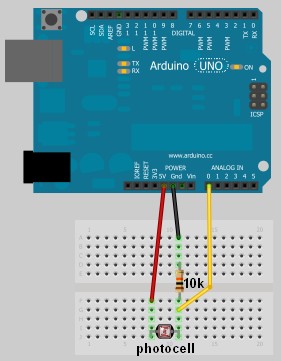
As you can see on drawings above, inputs are AC coupled with caps, and biased with 1.25V generated by LM317. Connector for other two inputs not installed yet.
Software.


Project keeps almost same structure of commands (CLI – command line interface) as its ancestor, with only two new for channel and gain selection. Read comments, it explains how to use them. One more things, I removed “r” – re-print option from the list of available commands.
Have fun!.
Link to arduino Leonardo sketch: Oscilloscope_Leonardo.
********************************************* Version 4*********************************************
Well, even posted above sketch has low complexity, and its good for beginning, nevertheless it’s quite limited as measuring device. The most important feature for oscilloscope, except V/div, is T/div, or timing, that has to be as much precise as possible. This is why “standard” timing options based on TIMER1 were add to next version of software. There are 9 time settings Time/div (10 samples):
50ms, 20ms, 10ms, 5ms, 2ms, 1ms, 500us, 200us, 100usec
corresponding to
200Hz, 500Hz, 1kHz, 2kHz, 5kHz, 10kHz, 20kHz, 50kHz, 100kHz
sampling rate. You can choose any of of this in the same manner, entering a digit 1-9 and letter d (display). Zero would skip capture, and just do whatever next letter request. Basically, 0 should be used to print channels data from memory. Combination: 9d0i – capture at 100 kHz rate, print chart and info-table,
4c2g7d – select 4-th channel, set gain to 10, select 20 kHz sampling rate and display.
I also add multichannel sampling capability. Commands 2m, 3m or 4m would configure oscilloscope for 2, 3 or 4 channels simultaneously capturing input waveform. As arduino has only 1 ADC, switching in multichannel mode would reduce sampling rate proportionally to number of channels, and this changes would be reflected in right top corner of the display. What more, arduino would automatically change vertical resolution per channel, to fit all 2 – 4 charts on one screen!


Known caveats:
Link to arduino Leonardo sketch: Oscilloscope_LeonardoV4
********************************************* Version 5*********************************************
New updated version. I was thinking how to improve simplest ever oscilloscope, and have made some structural changes in the code, mostly related to sampling in multichannel mode.
First of all, instead of “delay” 2 microseconds, that was used to give a multiplexer (and PGA amplifier) time to “settle” on new channel, I decided not to waste a time (that may be priceless in real-time application), rather start new conversion, than track samples based on the “history” of MUX settings, and store new sample in corresponding two dimensional array box. Now MUX and PGA would have more time, and consequently I could reduce ADC pre-selector’s clock to get better readings. It solved all the problems with wrong association port number and picture on the screen.
Secondly, as you, probably, already notice I’ve been working on another project recently, where phase is a PRIME factor of the whole idea of the design. Phase noise is a jitter, and it degrades spatial resolution and the sensitivity of the sound localization. Jitter always would be presented in the incoming signal – sampled waveform due “not synchronous” way of sampling, as “start new conversion” events were generated in “manual” mode. As microprocessor spend different amount of time to get inside of the ISR (interrupt subroutine) depends on where it was interrupted, time frame of the events, basically, was not defined. In order to get rid off the phase noise, I changed ADC settings to be triggered via TIMER 1. There is a code:
For some unknown for me reason, Atmel designed TIMER 1 channel B to be an auto trigger source of the ADC, the same time to run TIMER 1 itself in CTC mode, channel A must be set. I simply “bind” two channels A and B in “parallel”, so both of them rise interrupt flag at the same moment, only A re-starts a TIMER 1, and B generates “start new conversion” event and calling ISR for “maintenance” – take a new sample waiting in the line and switch a MUX to another channel of the oscilloscope.
The only issue that not solved yet, is a sampling in multichannel mode in “9″ T/div. Probably, Atmel just was not design to do such things…


|
|

1 | /* Stage 7: Simple Arduino Serial Random Number Generator |
1 | /* Some of the Serial code was adapted from Tom Igoe's example |
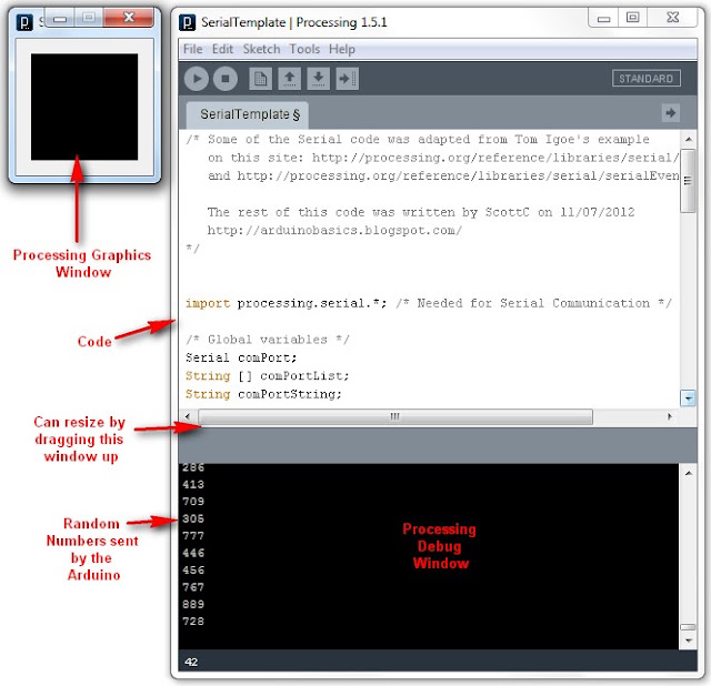
32 | if(comPortList.length>0){ |
32 | if(comPortList.length>0){ |
1 | /* Stage 8: Simple Arduino Serial Random Number Generator |
1 | /* Simple Serial ECHO script : Written by ScottC 03/07/2012 */ |


1 | /* Simple Serial ECHO script : Written by ScottC 04/07/2012 */ |
1 | /* Simple Serial ECHO script : Written by ScottC 05/07/2012 */ |
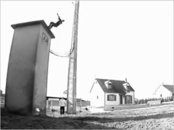
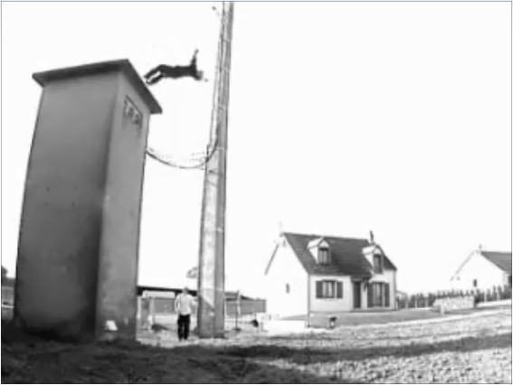
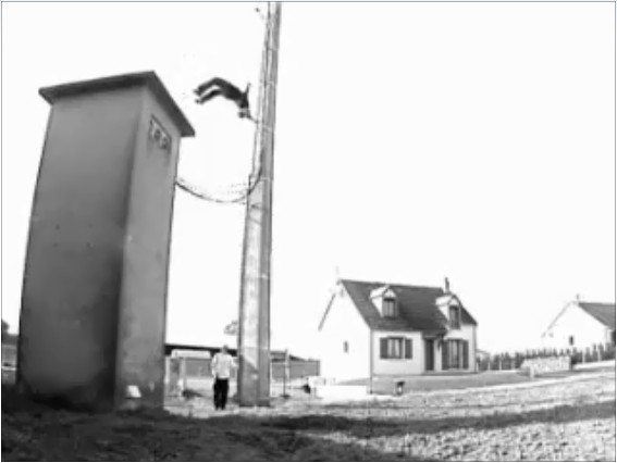
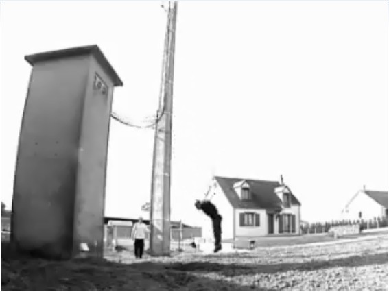
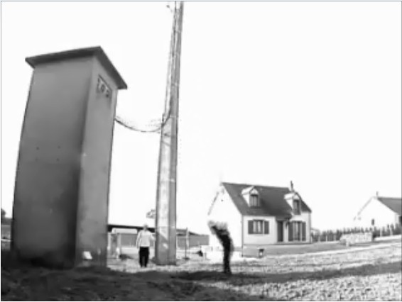
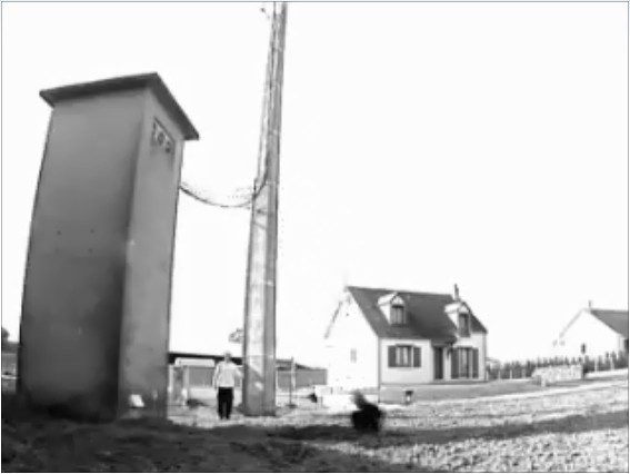
1 | /* Jumper: Using an Arduino to animate: |
1 | /* Jumper: Using an Arduino to animate |


1 | /* This program was created by ScottC on 9/5/2012 to receive serial |
1 | //Created by ScottC on 12/05/2012 to send mouse coordinates to Arduino |

1 |
|
1 |
|
1 |
|
I am currently working on a project where I need to teach my robot to "see" using an ultrasound sensor. In particular it must find and collect drink cans on a playfield and return them to a specific location.
To make the programming easier I wanted to take the sensor output from the robot and display it on the computer as a chart. As I am a terrible programmer I did a quick google search and came up with Gobetwenio.
Hey guys I am trying to read raw data from a gps module using TTL communication on RX pin 0 on the arduino mega. i dont know how to program it since i am total noob at arduino programming.
can someone help me out please.