Posts with «tachometer» label

Arduino Tachometer Clock Fires on All Cylinders

We’re certainly no strangers to unique timepieces around these parts. For whatever reason, hackers are obsessed with finding new and interesting ways of displaying the time. Not that we’re complaining, of course. We’re just as excited to see the things as they are to build them. With the assumption that you’re just as enamored with these oddball chronometers as we are, we present to you this fantastic digital tachometer clock created by [mrbigbusiness].

The multi-function digital gauge itself is an aftermarket unit which [mrbigbusiness] says you can get online for as little as $20 from some sites. All he needed to do was figure out how to get his Arduino to talk to it, and come up with some interesting way to hold it at an appropriate viewing angle. The mass of wires coming out of the back of the gauge might look intimidating, but thanks to his well documented code it shouldn’t be too hard to follow in his footsteps if you were so inclined.

Hours are represented by the analog portion of the gauge, and the minutes shown digitally were the speed would normally be displayed. This allows for a very cool blending of the classic look of an analog clock with the accuracy of digital. He’s even got it set up so the fuel indicator will fill up as the current minute progresses. The code also explains how to use things like the gear and high beam indicators, so there’s a lot of room for customization and interesting data visualizations. For instance, it would be easy to scrap the whole clock idea and use this gauge as a system monitor with some modifications to the code [mrbigbusiness] has provided.

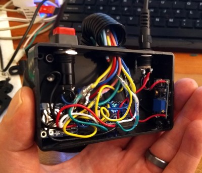
The gauge is mounted to a small project box with some 3D printed brackets and bits of metal rod, complete with a small section of flexible loom to cover up all the wires. Overall it looks very slick and futuristic without abandoning its obvious automotive roots. Inside the base [mrbigbusiness] has an Arduino Nano, a DS1307 RTC connected via I2C, a voltage regulator, and a push button to set the time. It’s a perfectly reasonable layout, though we wonder if it couldn’t be simplified by using an ESP8266 and pulling the time down with NTP.

We’ve seen gauges turned into a timepiece before, but we have to admit that this is probably the most practical realization we’ve seen of the idea yet. Of course if you want to outfit the garage with something a bit more authentic, you can always repurpose a Porsche brake rotor.

Tachometer Uses Light, Arduinos

To measure how fast something spins, most of us will reach for a tachometer without thinking much about how it works. Tachometers are often found in cars to measure engine RPM, but handheld units can be used for measuring the speed of rotation for other things as well. While some have mechanical shafts that must make physical contact with whatever you’re trying to measure, [electronoobs] has created a contactless tachometer that uses infrared light to take RPM measurements instead.

The tool uses an infrared emitter/detector pair along with an op amp to sense revolution speed. The signal from the IR detector is passed through an op amp in order to improve the quality of the signal and then that is fed into an Arduino. The device also features an OLED screen and a fine-tuning potentiometer all within its own self-contained, 3D-printed case and is powered by a 9 V battery, and can measure up to 10,000 RPM.

The only downside to this design is that a piece of white tape needs to be applied to the subject in order to get the IR detector to work properly, but this is an acceptable tradeoff for not having to make physical contact with a high-speed rotating shaft. All of the schematics and G code are available on the project site too if you want to build your own, and if you’re curious as to what other tools Arduinos have been used in be sure to check out the Arduino-based precision jig.

An Arduino tachometer for your older vehicle

Unlike most cars today, deepsyx’s old Opel Astra did not have a tachometer. So what’s a Maker to do? Build your own, of course.

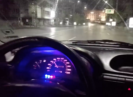
To accomplish this, deepsyx used an Arduino Uno along with a few LEDs. The first LED turns on at 4000 RPM, while the others light up with every 500 RPM increment. At 5800 RPM, however, all the LEDs flash as a warning. There’s even a serial output of the RPM value, so logging real-time data can be a possible enhancement down the road.

I started by cutting a 5cm x 1.5cm piece of an old credit cart, drilled 4 holes in it, painted it black and glued 4 LED diodes to it. Then I soldered 220ohm resistors to each positive LED pin and used a common ground. I connected them to an Arduino via 5 x 30cm jumpers and hid the Arduino in a hole under the wheel. I connected the Arduino data pin via voltage divider to the signal pin of the coil and used an old phone charger to power the Arduino. In order to work, I shared the phone charger and Arduino’s grounds.

Intrigued? You can read more about this project on deepsyx’sGitHub page and over on Hackaday.


Quick Arduino Hack Lets Tach-less Car Display Shift Points

A tachometer used to be an accessory added to the dash of only the sportiest of cars, but now they’re pretty much standard equipment on everything from sleek coupes to the family truckster. If your daily driver was born without a tach, fear not – a simple Arduino tachometer is well within your reach.

The tach-less vehicle in question is [deepsyx]’s Opel Astra, which from the video below seems to have the pep and manual transmission that would make a tach especially useful. Eschewing the traditional analog meter display or even a digital readout, [deepsyx] opted to indicate shift points with four LEDs mounted to a scrap of old credit card. The first LED lights at 4000 RPM, with subsequent LEDs coming on at each 500 RPM increase beyond that. At 5800 RPM, all the LEDs blink as a redline warning.  [Deepsyx] even provides a serial output of the smoothed RPM value, so logging of RPM data is a possible future enhancement.

The project is sensing engine speed using the coil trigger signal – a signal sent from the Engine Control Unit (ECU) which tells one of the ignition coilpacks to fire. The high voltage signal from the coilpack passes on to the spark plug, which ignites the air-fuel mixture in that cylinder. This is a good way to determine engine RPM without mechanical modifications to the car. Just make sure you modify the code for the correct number of cylinders in your vehicle.

Simple, cheap, effective – even if it is more of a shift point indicator than true tachometer, it gets the job done. But if you’re looking for a more traditional display and have a more recent vintage car, this sweeping LED tachometer might suit you more.

[via r/Arduino]


Filed under: Arduino Hacks, transportation hacks

Instrument Cluster Clock Gets The Show On The Road

While driving around one day, [Esko] noticed that the numbers and dials on a speedometer would be a pretty great medium for a clock build. This was his first project using a microcontroller, and with no time to lose he got his hands on the instrument cluster from a Fiat and used it to make a very unique timepiece.

The instrument cluster he chose was from a diesel Fiat Stilo, which [Esko] chose because the tachometer on the diesel version suited his timekeeping needs almost exactly. The speedometer measures almost all the way to 240 kph which works well for a 24-hour clock too. With the major part sourced, he found an Arduino clone and hit the road (figuratively speaking). A major focus of this project was getting the CAN bus signals sorted out. It helped that the Arduino clone he found had this functionality built-in (and ended up being cheaper than a real Arduino and shield) but he still had quite a bit of difficulty figuring out all of the signals.

In the end he got everything working, using a built-in servo motor in the cluster to make a “ticking” sound for seconds, and using the fuel gauge to keep track of the minutes. [Esko] also donated it to a local car museum when he finished so that others can enjoy this unique timepiece. Be sure to check out the video below to see this clock in action, and if you’re looking for other uses for instrument clusters that you might have lying around, be sure to check out this cluster used for video games.

The mechanics in dashboards are awesome, and produced at scale. That’s why our own [Adam Fabio] is able to get a hold of that type of hardware for his Analog Gauge Stepper kit. He simply adds a 3D printed needle, and a PCB to make interfacing easy.


Filed under: car hacks, clock hacks

Thermal control loop working (sort of)

Classes start tomorrow, so I spent yesterday making sure that the incubator control project was feasible. I had gotten the fan feedback control working well back in September, but I’d put the project aside for Fall quarter and only got back to it this week.  As a reminder, here are the previous posts on the project:

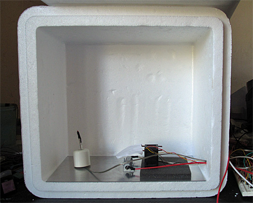
Here is the interior of the styrofoam box, with the lid open. The 6″×12″ aluminum plate covers the bottom. The thermistor is on the left, propped up by a rubber foot, the resistor in is the center, and the fan is sitting on a foam pad on the right. (The foam is to reduce noise until I can get the fan proper mounted in a baffle.)

I left the foam out this time, which made for a somewhat noisy fan, and I still haven’t built a baffle—I’m still using the bent-wire-and-paper deflector shown in the photo. What I worked on yesterday was the software—since the temperature changes are fairly slow, it takes a long time to tune the control loops.

One thing I did was to try to reduce measurement noise further on the thermistor measurements. I now add 60  analog-to-digital readings. They’re 10 bits on the Arduino-compatible board (a Sparkfun redboard), so adding 60 still fits in an unsigned 16-bit word. I now get noise of about ±0.05°C, which is half the least-significant-bit of the converter.  I doubt that I can do better in precision without switching to a processor with a better analog-to-digital converter, though I could do digital filtering with a 1Hz low-pass filter to smooth out the remaining noise.

I copied the fan feedback control loop (with the anti-windup provisions) described in Improving feedback for fan for temperature control, but made two changes:

  • I changed the integration time and K_p for the thermal control loop, since the temperature response is much slower than the fan response.
  • Because of the huge asymmetry in the temperature response (the resistor and metal plate can heat up much more quickly than they cool down), I turn off the heater the moment it gets over temperature, no matter with the PI loop suggests, but I only switch to full-on when the air temperature is 3°C too cold. For the fan, I used a symmetric window around the set point for using the PI loop rather than full-on/full-off.

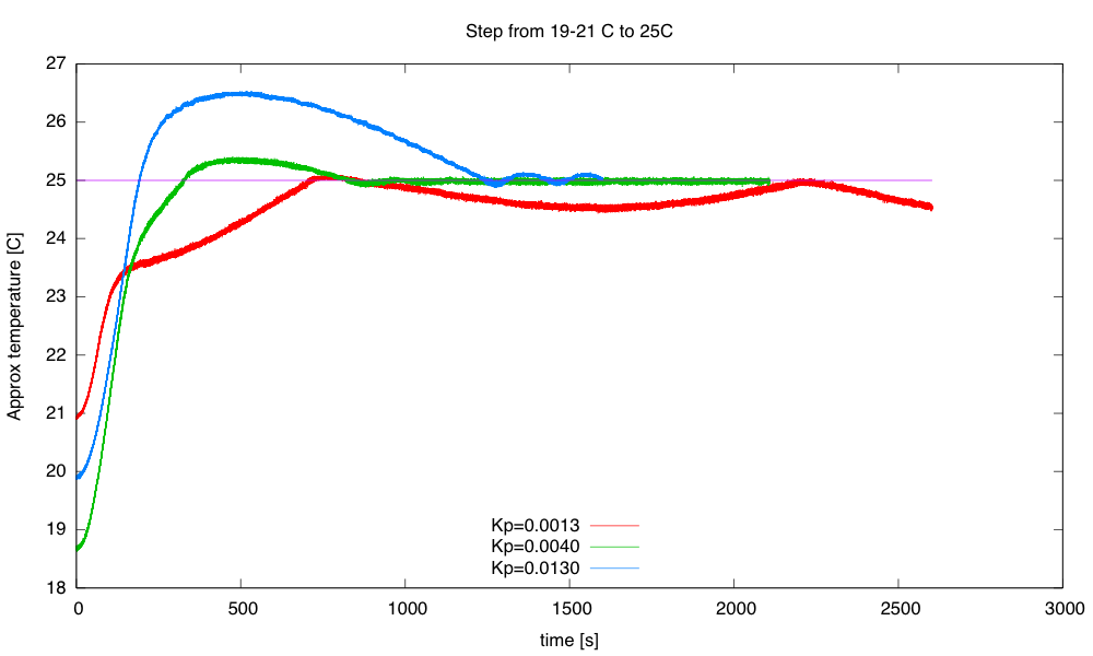
Here are some results from tuning experiments:

The blue curve switched to PI control at 23.5°C, the other two at 22°C. The green curve has pretty tight control over the temperature, but does overshoot a bit.

The initial temperatures were not all identical, because I wasn’t always willing to let everything cool down all the way to room temperature after each tuning run. I could only do about 1 tuning run an hour, which could pose problems for the freshman design seminar, as we don’t have long lab times—only the 70-minute lecture-schedule meeting times.

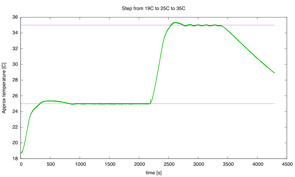
I continued the best of those runs with another step, up to 35°C, then let it cool down.

The step to 35°C has more ringing than the step to 25°C. I terminated the run before it had finished cooling, because the 32-bit µs timer wrapped around.

The cool-down at the end fits a 0.0069 °C/s line better than it fits an exponential decay to the ambient temperature.  If I do fit an exponential decay curve, I get a time constant of around 1975 seconds.

A simple thermal-resistance, thermal-capacity model is not a very good one for predicting how the system will behave, particularly since we’re not measuring the temperature of the large thermal mass (the aluminum plate and power resistor), but of the air, which has a large thermal resistance from the plate.  The time constant for the aluminum-air transfer is larger than the time constant for the electricity-aluminum transfer, which is why we get so much overshoot when we turn off the power to the resistor—the aluminum plate has gotten much hotter than the air, and continues to transfer heat to it, even though no more heat is being added to the aluminum.

Still, it is worth seeing what we get if we model the box a simple thermal mass and thermal resistor. The steady-state 35°C seems to need about 9W (PWM of 51/256) and the 25°C 3W (PWM of 17/256) with an ambient temperature of about 19°C, implying that the styrofoam box has a thermal resistance of about 1.9°C/W.

To see what is really going on, I’ll have to heat the box to 35°C, then start the cool down with a reset 32-bit timer.

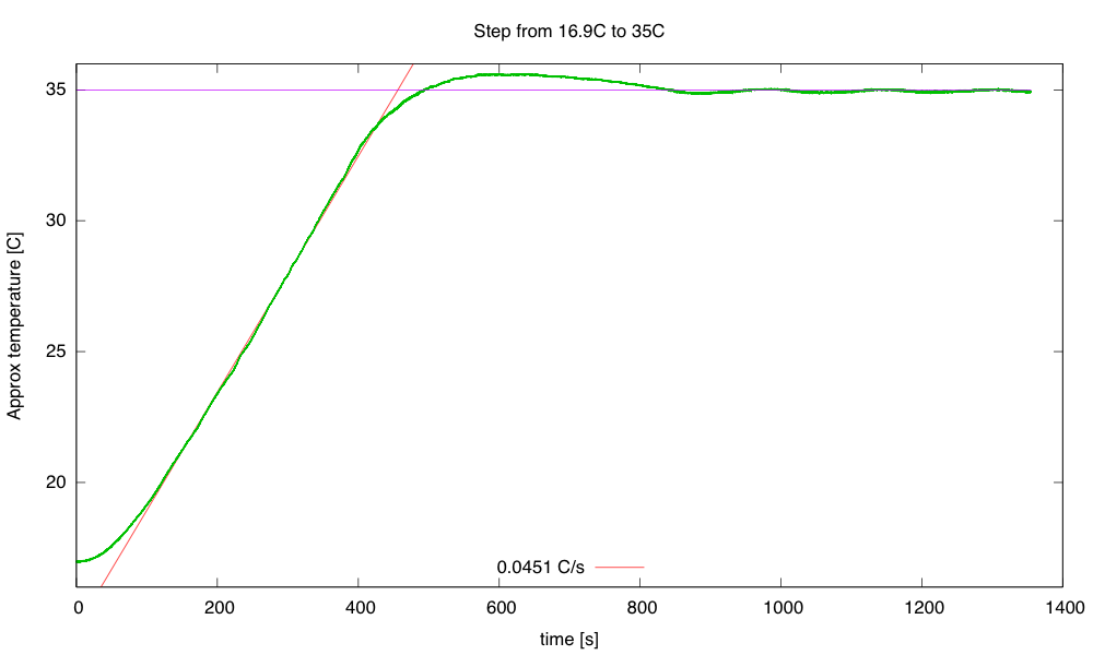
Single-step warming from 16.9°C to 35°C. The steady state at 35°C is about 9.32W, for a thermal resistance of 1.8°C/W. The rise of 0.0451°C/s at 45W implies a thermal capacity of 998 J/°C.

Heating at 45W (9V, 1.8Ω) results in a temperature rise of about 0.0451 °C/s. This warm-up rate at 45W implies a thermal capacity of about 998 J/°C. We may want to adjust our thermal capacity estimate, since some of the 45W put in escapes through the box—maybe about 3–4W at the temperatures where the rise was measured. This reduces the thermal capacity estimate to about 910 J/°C.

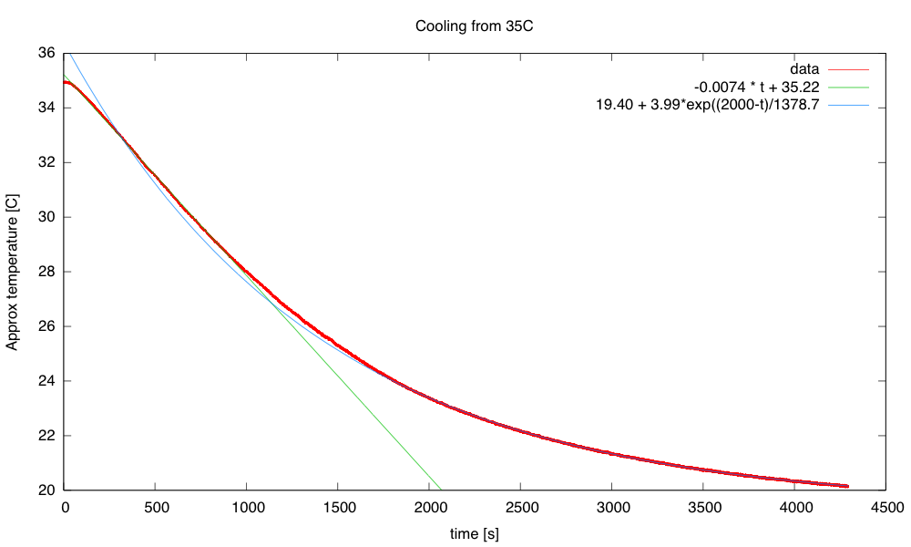
The cool down from 35°C starts out as a straight line (about -0.0074°C/s or -26.5°C/hour), but gradually starts behaving more like the exponential we would expect from a thermal-resistance and thermal-capacity model.

The time constant for the cooling is about 1380s, but the initial cooling is too slow for a simple exponential.

The time constant of 1380 s, combined with a thermal capacity of 910 J/°C gives a thermal resistance of 1.5 °C/W, a bit lower than the 1.8°C/W I estimated from the steady-state power.

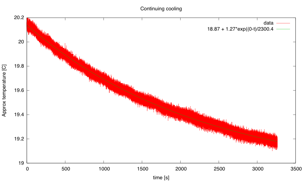
I continued the cooling (with the timer wrapped around) to see if I got a clean exponential at low temperature differences:

The exponential seems to fit well here, with a time constant of 2300s. Combined with the 910 J/°C, this gives a thermal resistance of 2.5°C/W, which seems a little high compared to the other estimates.

So I’ve made some progress on the thermal control loop (though I’d like to reduce the overshoot and ringing) and I have a crude model for the box: a thermal mass with capacity about 910 J/°C and thermal resistance 2±0.5 °C/W.

Still on my to-do list for this project:

  • Consider using a PID controller for the temperature to get faster response without overshoot.  (If I can reduce the noise problem.) I should be able to reduce the noise with a digital filter, but I’m already pushing well beyond what I’m comfortable covering in a freshman class. Tuning a PID controller is even trickier than tuning a PI controller, which is already going to take most of the quarter to teach.
  • Design and build baffling for the fan to get better airflow in the box. This might be a good thing to get students to do, particularly if we can get them to learn how to use the laser cutter. But even handsaws would suffice, given some thin plywood or masonite, some angle irons, and nuts and screws.
  • Figure out how to get students to come up with workable designs, when they are starting from knowing nothing. I don’t want to give them my designs, but I want to help them find doable subproblems. Some of the subproblems they come up with may be well beyond the skills that they can pick up in the time frame of the course. The more I work on this project, the more I realize that I and the students will have to be happy with them having explored the options, without getting all the problems solved.
  • Add changes to the cumulative error term whenever KP or TI are changed, to keep the PWM output the same after the changes—currently changing any of the control loop parameters adds a huge disturbance to the system. I don’t know how important this is—I’ve been doing my tuning of the thermal loop by recompiling, rather than by changing parameters on the fly. The quick changes were handy for the fan loop, where I could see things happening quickly, but for the thermal loop each experiment took about an hour, so there was no need for a fast parameter change.
  • Research control algorithms other than PI and PID, particularly for asymmetric systems like the temperature control, where I can get fairly quick response to the inputs when heating, but very slow response when cooling. The asymmetric window for switching between on/off and PI control seems to have helped here, but there is probably a more principled way to handle asymmetric control inputs. Maybe I should ask some of the control-theory faculty for some pointers.
  • Develop a more detailed thermal model with separate components for the aluminum plate and the air in the box. It may be worth adding another thermistor, taped to the aluminum plate, to monitor that temperature. The extra thermistor would also allow much tighter temperature control, avoiding overshoot on air temperature.


Filed under: freshman design seminar Tagged: Arduino, control loop, fan, incubator, integrator windup, PID controller, power resistor, PWM, tachometer, thermal resistance, thermistor

Improving feedback for fan

I wanted to look at the step response of the fan and of the heater, so that I could see if I could derive somewhat reasonable control parameters by theory, rather than by cut-and-try parameter fiddling.  Most of the tutorials I’ve looked at give empirical ways of tuning PID controllers, rather than theoretical ones, even ones that use Laplace transforms to explain how PID controllers work and how to determine whether or not the control loop is stable if you are controlling a linear time-invariant system with a known transfer function.

When I first looked at the fan response, I noticed a problem with my tachometer code:
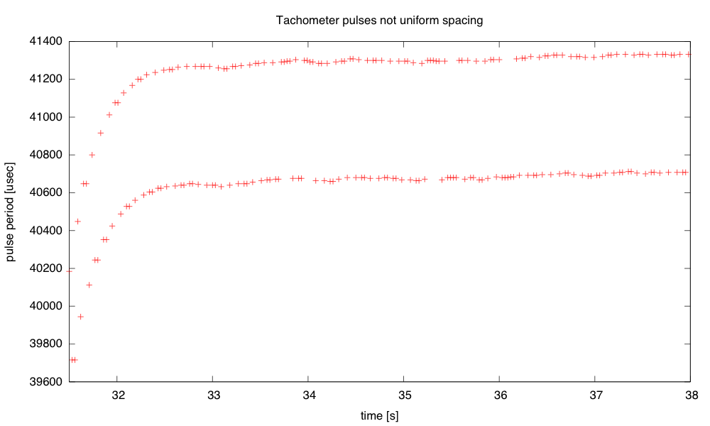
The tachometer gives two pulses per revolution, but the markers used are not perfectly spaced, so I get different estimates of the speed depending which falling-edge-to-falling-edge pulse width I measure. The difference between the two speeds is about 1.6%.

I rewrote the tachometer code to trigger on all four edges of a revolution, and to record the time at each edge in a circular buffer. This way I can use a full revolution of the fan for determining the speed, but get updated estimates every quarter revolution, available in micros_per_revolution:

volatile uint32_t old_tach_micros[4];  // time of last pulses of tachometer
	// used as a circular buffer
volatile uint8_t prev_tach_index=0;    // pointer into circular buffer
volatile uint32_t micros_per_revolution; // most recent pulse period of tachometer

#define MIN_TACH_PULSE  (100)   // ignore transitions sooner than this many
				// microseconds after previous transition

void  tachometer_interrupt(void)
{   uint32_t tach_micros = micros();

    if (tach_micros-old_tach_micros[prev_tach_index] < MIN_TACH_PULSE) return;
    prev_tach_index = (prev_tach_index+1)%4;  // increment circular buffer pointer
    micros_per_revolution= tach_micros-old_tach_micros[prev_tach_index];
    old_tach_micros[prev_tach_index] = tach_micros;
}

In setup(), I need to set up the interrupt with attachInterrupt(FAN_FEEDBACK_INT,tachometer_interrupt, CHANGE);

I think that this improved tachometer code may be a bit too much for first-time programmers to come up with. Circular buffers use a bunch of concepts (arrays, modular arithmetic) and are likely to cause a lot of off-by-one errors. Interrupts alone were a complicated enough concept for students to deal with. I don’t know whether the improvement in speed measurement would be justifiable in the freshman design course.

The new tachometer code did smooth out the measurements a lot, though, as expected—it reduces the fluctuation in measured speed to about 0.3%, which is limited by the resolution of the micros() timer I’m using on the Arduino board. I then tried recording some step responses, both for upward steps and downward steps. The upward steps are reasonably approximated by an exponential decay (like a charging curve):
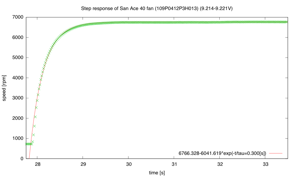
The low speed with PWM=0 (always off) is 724.7 rpm, and the high speed with PWM=255 (always on) is 6766.3rpm. The exponential fit is not perfect, but it is certainly a good enough approximation for designing a closed-loop system.

The response to a downward step, however, is not well modeled by a simple exponential decay:
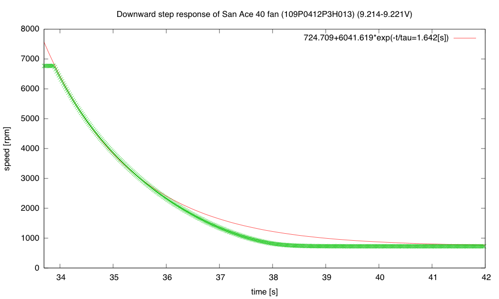
The fan spins down gradually at first (with a time constant about 1.6s), but at low speed the speed changes faster (as if the time constant dropped to about 0.6s).

Note that the fan slows down much more gradually than it speeds up, which means that it is not a linear, time-invariant system. In a linear system, superimposing a step-up and a step-down would cancel, so the responses to the step up and step down should add to a constant value—the fan most definitely does not have that property.

I was curious whether the difference was just apparent for large steps, or also for small ones, so I tried steps between PWM duty cycles of 100/256 and 160/256:
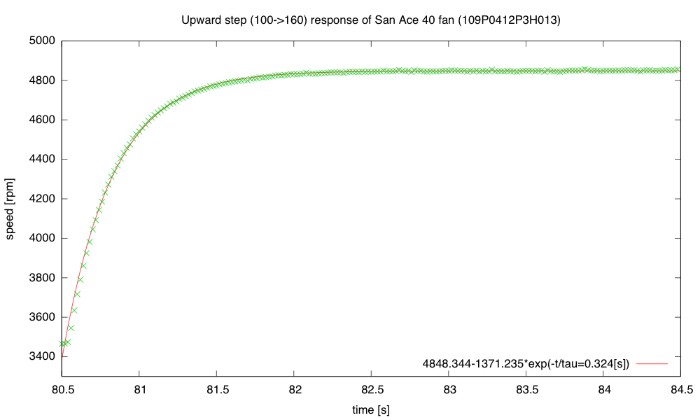
A small upward step is again quick, with almost the same time constant as before.
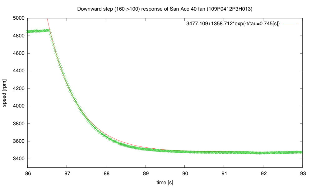
The small downward step is faster than before, though still substantially slower than the upward step of the same size, and with an initially slower response than the final convergence.

I’m going to try writing a couple of ad hoc controllers for the fan, to see if they behave better than the PID controller I’ve been using: open-loop control using just  PWM=(setpoint-740)/25; a simple on/off control with a single threshold; hysteresis, using two thresholds instead of 1; PI control with no anti-windup; and a controller that goes to full on or full off when the error is large, to make a quick transition,  switching to approximately the right PWM value,  when the error is small, with PI control thereafter.

I think that the open-loop controller will have a steady, but wrong speed; the  crude on/off controllers will make an audible pulsing of the fan motor; the PI controller will suffer from overshoot when making big steps, and the on/off/PI controller should make nice steps, if I can tune it right.

I implemented all the controllers and ran a test switching between setpoints of 1000RPM and 5000RPM every 30 seconds.  Here are plots of the behavior with different control algorithms:
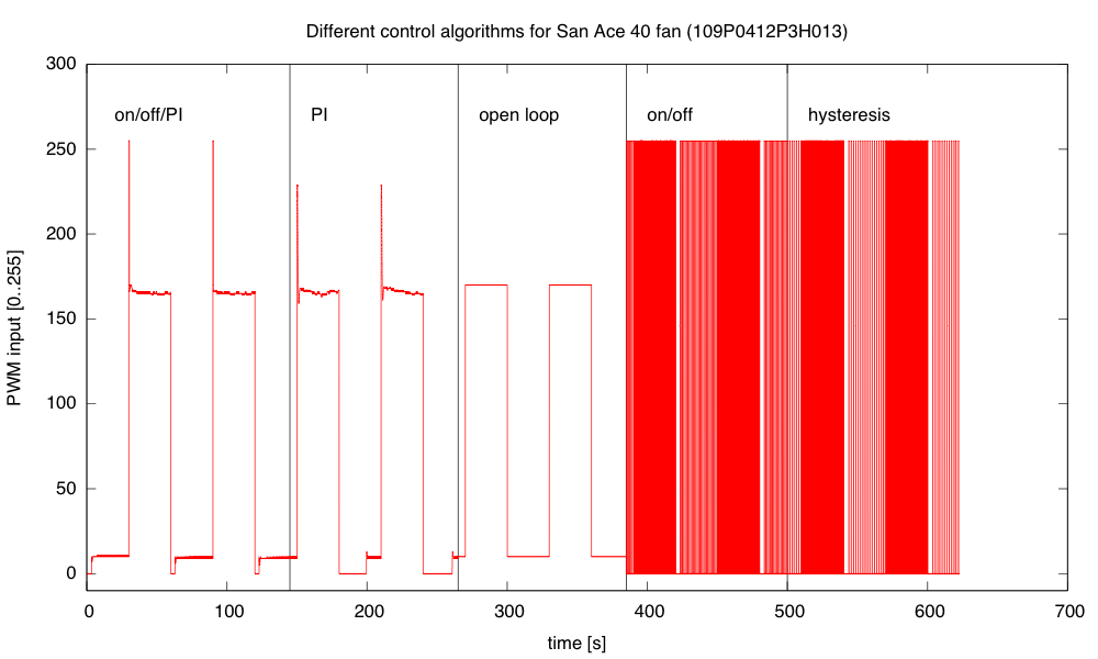
The PWM values computed by the various control algorithms show the integrator windup problem for PI clearly after the downward transitions—PI takes a long time to recover from the errors during the downward edge.
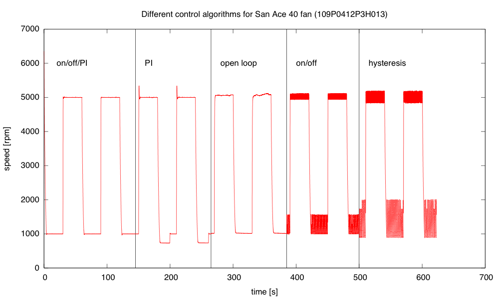
The mixed algorithm does a very good job of control, with little overshoot. The simple PI algorithm has substantial overshoot, particularly when the control loop wants a PWM value outside the range [0,255]. Open loop has significant offset and wanders a bit. On/off control oscillates at about 10hz, and adding hysteresis makes the oscillation larger but slower (about 5Hz).

The errors for the mixed controller are only about ±0.3% and overshoot or ringing at the transitions <40RPM.  The simple PI controller overshoots by 340RPM and takes 20 seconds to recover from the integrator windup on the downward transition.  The open-loop controller has offset errors of about 1% and a fluctuation of about ±0.7% at the high speed, and an offset of 1% and fluctuations of about ±0.5% at the low speed.  The on/off controller has an offset of  about 0.5% at high speed with fluctuations of ±2%, and an offset of 28% with fluctuations of ±28%.  Adding hysteresis slows down the oscillations, but makes them larger (0.2% offset, fluctuations ±3% at high speed, and 44% offset with fluctuations of ±70% at low speed).The mixed algorithm which uses on/off control for large errors and PI for small errors, with back-calculation of the integral error when switching to the PI controller seems to work very well.  But would I be able to get freshmen to the point of being able to develop that themselves within a 2-unit course?  Probably not, but I might be able guide them through the development in a series of exercises that started with on/off control, then went to modeling and open-loop control, then the PI control, and finally the mixed control.  It would take most of the quarter.


Filed under: freshman design seminar Tagged: Arduino, control loop, fan, incubator, PID controller, PWM, tachometer

Putting the heater in a box

Continuing the saga of the incubator project in the recent posts:

On my to-do list for the project

  • Put the whole thing into a styrofoam box, to see whether extra venting is needed to allow things to cool down, and to see how tightly temperature can be controlled. Find a smaller bread board or prototype board to put the controller on—my current bread boards are all 6.5″ long, and the box only has room for 6″, especially since I put the resistor in the center of the 6″×12″ aluminum plate, which just fits the box. I suppose I could drill a couple more holes in the plate and mount the resistor off center, but I rather like the idea of building the controller as an Arduino shield, so that the Arduino + controller is a single unit. Another possibility is to drill a hole in the styrofoam box and run cables through the box for the resistive heater, the fan, and the thermistor. Even if the grounds are connected outside the box, this is only 8 wires. Putting the control electronics outside the box would reduce the clutter in the box and make tweaking easier

    I got this done today, by drilling a hole in the box and soldering long wires onto the resistor and the thermistor, so that all the active electronics could live outside the box. Incidentally, “drilling” did mean using a drill bit, but I held it and turned it with my fingers—styrofoam is so soft and grainy that I feared a power drill would tear out big chunks.

    Here is the interior of the styrofoam box, with the lid open. The 6″×12″ aluminum plate covers the bottom. The thermistor is on the left, propped up by a rubber foot, the resistor in is the center, and the fan is sitting on a foam pad on the right. (The foam is to reduce noise until I can get the fan proper mounted in a baffle.)

    As expected, I can heat up the thermistor fairly quickly, but if I overshoot on the temperature, it takes a very long time for the closed box to cool back down. Cooling off just 1°C took over half an hour.

  • Add some low-pass filtering to the temperature measurement to reduce noise. Just adding 4 measurements in quick succession would reduce the noise and give the illusion of extra precision.

    I did this also. With the box closed, the thermistor reading is fairly stable, with fluctuations of less than 0.1°C (which was the resolution with a single thermistor reading before adding 4 successive reads).

  • The fan controller occasionally has a little glitch where the tachometer either misses a pulse or provides an extra one (I think mainly an extra one due to ringing on the opposite edge).  I could try reducing this problem in three ways: 1) changing which edge I’m triggering on, 2) using more low-pass filtering before the Schmitt trigger in the edge detector, or 3) using median filtering to throw out any half-length or double-length pulses, unless they occur as a pair.  (Hmm, the half-length pulses would occur as a pair, so this might not help unless I go to median of 5, which would be a lot of trouble.)

    I fixed this also, using two techniques:

    1. In the program I have 3 states for the interrupt routine that catches the edges: normally, I check that the edge is within 3/4 to 3/2 of the previously recorded pulse—if so I record it and continue. If it is less than 3/4 as long, I skip it, and change to a skip state. If it is more than 3/2 as long, I skip it and switch to a force state. In the skip state, I ignore the reading and switch to the force state. In the force state, I accept the pulse length (whatever it is), and switch to the normal state. With this state machine, I ignore a double-length pulse or a pair of half-length pulses together.
    2. The rising edge of the pulse from the tachometer is very slow (thanks to the RC filter of the pullup), but the falling edge is sharp. Extraneous pulses are more likely to occur if I trigger on the slow edge rather than fast edge, so I switched the polarity to make sure that I was using the falling edge (which is the rising edge of the output of the Schmitt trigger).

    I think that changing which edge I used made a bigger difference than trying to suppress the erroneous reads digitally. I no longer hear the occasional hiccup where the control algorithm tries desperately to double or half the fan speed because of a misread timing pulse.

  • Improve my anti-windup methods for both thermal and fan controllers, to reduce overshoot.

    I changed from using conditional integration and back calculation of the integration error to using a decay of the integration error based on the difference between the computed PWM setting and the limit when the limits were exceeded. I’m not sure this improved anything though, and it introduces yet another parameter to tune, so I may go back to the previous method. I did play around with the tuning parameters for the fan loop today, and realized that I still don’t have good intuition about the effect of parameter changes. I noticed that the fan control was oscillating a little (small fluctuations around the desired speed, but big enough that I could hear the changes), and I found ways to reduce the oscillations, but at the expense of slower response to step changes.

  • Improve my modeling of the thermal system, so that I can do more reasonable back calculation on setpoint change.

    I still need to do more thinking about the thermal modeling, since it is clear that I can’t afford overshoot when heating (though overshoot during slow cooling is unlikely to be a problem).

Still on my list with no progress:

  • Consider using a PID controller for the temperature to get faster response without overshoot.  (If I can reduce the noise problem.)
  • Design and build baffling for the fan to get better airflow in the box. I’ve made a little paper and wire baffle, to get better air flow over the resistor, but I’ve not done the full baffling to get good airflow in the box.
  • Figure out how to get students to come up with workable designs, when they are starting from knowing nothing. I don’t want to give them my designs, but I want to help them find doable subproblems. Some of the subproblems they come up with may be well beyond the skills that they can pick up in the time frame of the course. The more I work on this project, the more I realize that I and the students will have to be happy with them having explored the options, without getting all the problems solved.

I want to add to the list today:

  • Add changes to the cumulative error term whenever KP or TI are changed, to keep the PWM output the same after the changes—currently changing any of the control loop parameters adds a huge disturbance to the system.
  • Separate the control algorithm better from the rest of the code, so that I can use the same code base and quickly switch between different control algorithms: on/off, on/off with hysteresis, proportional control, proportional control with offset, PI control, PI control with anti-windup variants, PID control.
  • Add an option for recording the response of the system over a long time, so that I can plot input and output of the system with gnuplot. This would be nice for the fan control loop, but I think it will be essential for the temperature control loop.
  • Research control algorithms other than PI and PID, particularly for asymmteric systems like the temperature control, where I can get fairly quick response to the inputs when heating, but very slow response when cooling.

Filed under: freshman design seminar Tagged: Arduino, control loop, fan, incubator, integrator windup, PID controller, power resistor, PWM, tachometer, thermistor