Posts with «module» label

Matrix and Joystick

For the original tutorial, please visit: https://arduinobasics.blogspot.com


Project Description

In this project, we will use a little joystick to move a pixel around an 8x8 LED matrix. The joystick has a built-in button, such that when you press down onto the joystick, the colour of the pixel will change from red to blue to green. This is a very simple project, however, controlling the matrix adds a certain level of complexity. You will need to understand binary notation and bit-shifting techniques to grasp the concept of this tutorial.

All of the parts used in this project can be obtained from digitspace.com


Libraries

The SPI library is required for this project. However, this library is built into the current version of the Arduino IDE. No additional download is required. Just make sure to include it at the top of the sketch.


Arduino Code

The Arduino IDE can be downloaded from the official Arduino website: here.
Copy and paste the following code into your Arduino IDE and upload it to the Arduino UNO.


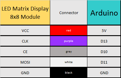
Connections


Project Video

As you can see from the video above, the pixel changes colour when the button is pressed. The position of the pixel relates to the position of the joystick. The lag between the joystick movement and pixel movement is minimal, and very satisfying.


Conclusion

This was a very fun and satisfying project that showcases the interaction between a joystick and a 8x8 LED matrix with the help of an Arduino UNO. This project was sponsored by the kind people at digitspace. Without their sponsorship, this tutorial would not have been possible. Please visit their website for some nice deals on Arduino related products.

If you found this tutorial helpful, please consider supporting me by buying me a virtual coffee/beer.

$3.00 AUD only

Social Media

You can find me on various social networks:

Follow me on Twitter: ScottC @ArduinoBasics.
I can also be found on Instagram, Pinterest, and YouTube.
And if all else fails, I have a server on Discord.


ScottC 09 Mar 07:41
8x8  arduino  ce  clk  fun  joystick  led  matrix  module  mosi  pixel  programming  spi  sw  tutorial  uno  x  y  

MT8870 DTMF - Dual Tone Multi Frequency Decoder

Project Description

We will be using an MT8870 DTMF module with an Arduino UNO to control a small servo motor in this project. The DTMF module gives the Arduino super-powers and allows you to control the Servo motor in so many ways. For example, this tutorial will show you how to control the servo motor using:
  • a YouTube Video
  • a voice recorder
  • A web application (Online tone generator)
  • A smart phone app (DTMF Pad)
  • A touch-tone phone to cell-phone call
All of these control methods will take advantage of the same exact Arduino code/sketch. But how???
The MT8870 DTMF decoder is quite a neat little module that allows you incorporate DTMF technology into your arduino projects. DTMF stands for Dual-Tone Multi-Frequency. DTMF tones are commonly associated with touch-tone phones and other telecommunication systems. When you press the number "1" on a touch-tone phone, two sine waves with frequencies: 697Hz and 1209Hz are combined to produce a unique DTMF signal which can be transmitted through the phone line. The MT8870 DTMF module can take this signal as an input, and decode it to produce a binary output.


The DTMF module does not care how you produce the DTMF tone. However, if it receives this tone, it will decode it. We can take advantage of this feature to supply the module with tones from different sources. The module has a 3.5mm port for line input. Providing you can connect your DTMF source to this line input in some way, it should work. I must warn you, however that this is a line input and NOT a microphone input. If you wanted to use a microphone, you will need to boost or amplify the signal before sending it to the DTMF module.
 
You will need the following parts for this project
 

Parts Required:

Software/Apps Required

Arduino Sketch


Upload the following sketch to the Arduino.
 

1
2
3
4
5
6
7
8
9
10
11
12
13
14
15
16
17
18
19
20
21
22
23
24
25
26
27
28
29
30
31
32
33
34
35
36
37
38
39
40
41
42
43
44
45
46
47
48
49
50
51
52
53
54
55
56
57
58
59
60
61
62
/* ================================================================================================================================================== Project: MT8870 DTMF Servo sketch Author: Scott C Created: 4th August 2015 Arduino IDE: 1.6.4 Website: http://arduinobasics.blogspot.com/p/arduino-basics-projects-page.html Description: This project will allow you to control a Servo motor using an Arduino UNO and a MT8870 DTMF Module. The DTMF signal is received through the 3.5mm port of the DTMF module and is decoded. We will use the decoded output to control the position of the Servo. A SG-5010 Servo motor was used in this project. ===================================================================================================================================================== *///This sketch uses the Servo library that comes with the Arduino IDE #include <Servo.h> //Global variables----------------------------------------------------------------------------------------- Servo SG5010; // The SG5010 variable provides Servo functionality int servoPosition = 0; // The servoPosition variable will be used to set the position of the servo byte DTMFread; // The DTMFread variable will be used to interpret the output of the DTMF module. const int STQ = 3; // Attach DTMF Module STQ Pin to Arduino Digital Pin 3 const int Q4 = 4; // Attach DTMF Module Q4 Pin to Arduino Digital Pin 4 const int Q3 = 5; // Attach DTMF Module Q3 Pin to Arduino Digital Pin 5 const int Q2 = 6; // Attach DTMF Module Q2 Pin to Arduino Digital Pin 6 const int Q1 = 7; // Attach DTMF Module Q1 Pin to Arduino Digital Pin 7 /*========================================================================================================= setup() : will setup the Servo, and prepare the Arduino to receive the MT8700 DTMF module's output. ========================================================================================================== */void setup() { SG5010.attach(9); // The Servo signal cable will be attached to Arduino Digital Pin 9 SG5010.write(servoPosition); // Set the servo position to zero. //Setup the INPUT pins on the Arduino pinMode(STQ, INPUT); pinMode(Q4, INPUT); pinMode(Q3, INPUT); pinMode(Q2, INPUT); pinMode(Q1, INPUT);} /*========================================================================================================= loop() : Arduino will interpret the DTMF module output and position the Servo accordingly ========================================================================================================== */void loop() { if(digitalRead(STQ)==HIGH){ //When a DTMF tone is detected, STQ will read HIGH for the duration of the tone. DTMFread=0; if(digitalRead(Q1)==HIGH){ //If Q1 reads HIGH, then add 1 to the DTMFread variable DTMFread=DTMFread+1; } if(digitalRead(Q2)==HIGH){ //If Q2 reads HIGH, then add 2 to the DTMFread variable DTMFread=DTMFread+2; } if(digitalRead(Q3)==HIGH){ //If Q3 reads HIGH, then add 4 to the DTMFread variable DTMFread=DTMFread+4; } if(digitalRead(Q4)==HIGH){ //If Q4 reads HIGH, then add 8 to the DTMFread variable DTMFread=DTMFread+8; } servoPosition = DTMFread * 8.5; //Set the servoPosition varaible to the combined total of all the Q1 to Q4 readings. Multiply by 8.5 to amplify the servo rotation. } SG5010.write(servoPosition); //Set the servo's position according to the "servoPosition" variable. }


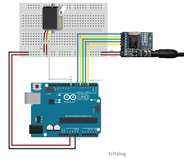
Fritzing Sketch


Connect the Arduino to the MT8870 DTMF module, and to a Servo.
Use the following Fritzing sketch as a guide.
 
(Click the image above to enlarge it)


Discussion


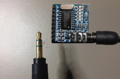
You will need to connect a cable from the DTMF module's 3.5mm port to that of your smart phone, computer, voice recorder or any other DTMF source of your choice.


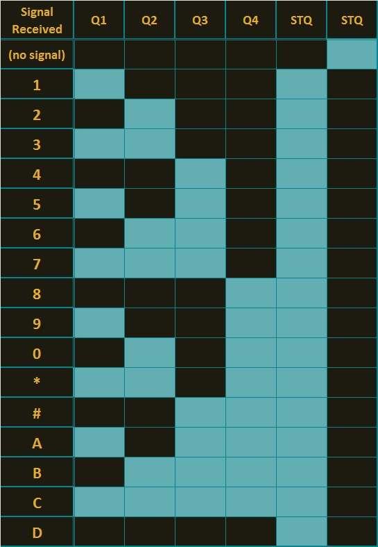
When you power up your Arduino, the Servo motor should turn all the way to the left to it's zero position. Once the DTMF module receives a DTMF signal, it will identify the relevant frequecies as described in the table at the beginning of this tutorial, and produce a binary like output. You will notice the DTMF module's onboard LEDs light up when a tone is detected. Onboard LED (D5) will turn on for the length of the DTMF tone it just received, and turn off when the tone has stopped. On the other hand, the onboard LEDs (D1 to D4) will light up depending on the tone received, and will remain lit until the module receives another tone. The onboard LEDs are a visual representation of the voltages applied to the DTMF module's pins (Q1 to Q4, and STQ). Q1 matches D1, Q2 matches D2 etc etc. and STQ matches D5.
 
You will notice that there are two STQ pins on the DTMF module. The STQ pin that is closest to Q4 will only go high when a DTMF tone is detected, and will remain high for the duration of the tone. The other STQ pin is the exact opposite. It will switch LOW when a tone is received and remain LOW for the duration of the tone. When there is no tone, this STQ pin will remain HIGH. The table below provides a summary of the DTMF module outputs, with a blue box representing a voltage applied to that pin (HIGH), whereas a black box indicates no voltage applied (LOW).


In order to follow this project, you need a source of DTMF tones. You can produce DTMF tones using a touch-tone phone, or through the use of a DTMF Pad app. If you are feeling creative, you can create a DTMF song/tune like the one I posted on YouTube. You can see the video below:


As you can see from the video, I also recorded the DTMF tune onto a voice recorder, and was able to control the servo that way. If you are not feeling creative, you can visit this website to create DTMF tones from your browser.

Concluding comments


This project was very fun, and shows some novel ways to control your Arduino. After completing the project, I realised that I could use this module to alert me when new emails or messages arrive on my phone or computer. If you have the ability to change the email or message notification sound to a DTMF tone, you should be able to get the module and Arduino to respond accordingly. Oh well, maybe I'll save that project for another day.
 
If this project helped you in anyway or if you use my code within your project, please let me know in the comments below. I would be interested to see what you did.


If you like this page, please do me a favour and show your appreciation :

 
Visit my ArduinoBasics Google + page.
Follow me on Twitter by looking for ScottC @ArduinoBasics.
I can also be found on Pinterest and Instagram.
Have a look at my videos on my YouTube channel.


However, if you do not have a google profile...
Feel free to share this page with your friends in any way you see fit.

CH376S USB Read/Write module

Have you ever wondered if there was a way to store and retrieve data from a USB stick with an Arduino UNO? Most people choose SD cards to store their project data, but you may be surprised there IS a way!
IC Station have a nice little module which allows you store and retrieve your Arduino (or other MCU) project data to a USB stick.
 
I am not too sure why USB storage is not widely used in Arduino projects? These modules are not expensive, they have been around for quite a while, and are relatively simple to use. You do not need any libraries to get them to work, however, I must say that documentation for this module is not that easy to find. This site and this document proved to be very useful in my endevour to get this module working, and I hope my tutorial below will help you get started and bridge some of the information gaps.
 
The "CH376S USB read/write module" has a CH376S chip onboard which does most of the hard work for you. All you have to do is send the module some commands from the Arduino and the CH376S chip will do the rest. You can communicate with the module in three different ways:

  • Parallel communication
  • SPI communication
  • and Serial (UART) communication.

This project will show you the connections and code for the Serial (UART) communication method only.


Parts Required:

Remove the Jumper

When the CH376S USB module arrives in it's package, it will have a jumper between the TXD pin and GND. You will need to remove this jumper to make the necessary connections between the Arduino UNO and the CH376S USB module.


Fritzing Sketch

Please note, that the Arduino Sketch makes use of the Arduino UNO's onboard LED on digital pin 13. The Fritzing sketch below shows an LED + 300 ohm resistor on a breadboard. This is optional. The LED is not a necessary component of CH376S module communication.

Also be aware that the CH376S USB module has an onboard LED just above the TXD and GND pins near the USB port. This LED will only turn on providing the CH376S module is in USB mode AND a USB device has been inserted into the USB port. Both conditions must be met before the module's onboard LED will illuminate. You will not see the LED turn on just by powering the board.
 
The wire diagram below is the correct setup for Serial communication between an Arduino UNO and the CH376S module. If you wish to use SPI or Parallel communication, you will need to refer to the datasheet.


Arduino Sketch


  1
2
3
4
5
6
7
8
9
10
11
12
13
14
15
16
17
18
19
20
21
22
23
24
25
26
27
28
29
30
31
32
33
34
35
36
37
38
39
40
41
42
43
44
45
46
47
48
49
50
51
52
53
54
55
56
57
58
59
60
61
62
63
64
65
66
67
68
69
70
71
72
73
74
75
76
77
78
79
80
81
82
83
84
85
86
87
88
89
90
91
92
93
94
95
96
97
98
99
100
101
102
103
104
105
106
107
108
109
110
111
112
113
114
115
116
117
118
119
120
121
122
123
124
125
126
127
128
129
130
131
132
133
134
135
136
137
138
139
140
141
142
143
144
145
146
147
148
149
150
151
152
153
154
155
156
157
158
159
160
161
162
163
164
165
166
167
168
169
170
171
172
173
174
175
176
177
178
179
180
181
182
183
184
185
186
187
188
189
190
191
192
193
194
195
196
197
198
199
200
201
202
203
204
205
206
207
208
209
210
211
212
213
214
215
216
217
218
219
220
221
222
223
224
225
226
227
228
229
230
231
232
233
234
235
236
237
238
239
240
241
242
243
244
245
246
247
248
249
250
251
252
253
254
255
256
257
258
259
260
261
262
263
264
265
266
267
268
269
270
271
272
273
274
275
276
277
278
279
280
281
282
283
284
285
286
287
288
289
290
291
292
293
294
295
296
297
298
299
300
301
302
303
304
305
306
307
308
309
310
311
312
313
314
315
316
317
318
319
320
321
322
323
324
325
326
327
328
329
330
331
332
333
334
335
336
337
338
339
340
341
342
343
344
345
346
347
348
349
350
351
352
353
354
355
356
357
358
359
360
361
362
363
364
365
366
367
368
369
370
371
372
373
374
375
376
377
378
379
380
381
382
383
384
385
386
387
388
389
390
391
392
393
394
395
396
397
398
399
400
401
402
403
404
405
406
407
408
409
410
411
412
413
414
415
416
417
418
419
420
421
422
423
424
425
426
427
428
429
430
431
432
433
434
435
436
437
438
439
440
441
442
443
444
445
446
447
448
449
450
451
452
453
454
455
456
457
458
459
460
461
462
463
464
465
466
467
468
469
470
471
472
473
474
475
476
477
478
479
480
481
482
483
484
485
486
487
488
489
490
491
492
493
494
495
496
497
498
499
500
501
502
503
504
505

/* ===============================================================
      Project: CH376S USB Read/Write Module testing ground
       Author: Scott C
      Created: 1st May 2015
  Arduino IDE: 1.6.2
      Website: http://arduinobasics.blogspot.com/p/arduino-basics-projects-page.html
  Description: This project will allow you to perform many of the functions available on the CH376S module.
               Checking connection to the module, putting the module into USB mode, resetting the module, 
               reading, writing, appending text to files on the USB stick. This is very useful alternative to
               SD card modules, plus it doesn't need any libraries.
================================================================== */

#include <SoftwareSerial.h>

byte computerByte; //used to store data coming from the computer
byte USB_Byte; //used to store data coming from the USB stick
int LED = 13; //the LED is connected to digital pin 13
int timeOut = 2000; //TimeOut is 2 seconds. This is the amount of time you wish to wait for a response from the CH376S module.
String wrData = "What is the meaning of life ?"; //We will write this data to a newly created file.
String wrData2 = "42"; //We will append this data to an already existing file.

SoftwareSerial USB(10, 11); // Digital pin 10 on Arduino (RX) connects to TXD on the CH376S module
                                                      // Digital pin 11 on Arduino (TX) connects to RXD on the CH376S module
                                                      // GND on Arduino to GND on CH376S module
                                                      // 5V on Arduino to 5V on CH376S module
//==============================================================================================================================================
void setup() {
  Serial.begin(9600); // Setup serial communication with the computer (using a baud rate of 9600 on serial monitor)
  USB.begin(9600); // Setup serial communication with the CH376S module (using the default baud rate of 9600)
  pinMode(LED,OUTPUT); // Define digital pin 13 as an OUTPUT pin - so that we can use it with an LED
  digitalWrite(LED,LOW); // Turn off the LED
}

//================================================================================================================================================
void loop() {
  if(Serial.available()){
    computerByte = Serial.read(); //read any incoming bytes from the Serial monitor, and store this byte in the variable called computerByte
    if(computerByte==49){ //1 //If you send the number 1 from the serial monitor, the arduino will read it as digital number 49. Google "ascii table" for more info.
      printCommandHeader("COMMAND1: CHECK CONNECTION");
      checkConnection(0x01);                           // Check for successful connection and communication with the CH376S module.
    } 
    if(computerByte==50){ //2
     printCommandHeader("COMMAND2: set_USB_Mode");
      set_USB_Mode(0x06);                              // Code used to enable read/write communication and monitoring of the USB stick
    }
    if(computerByte==51){ //3
      printCommandHeader("COMMAND3: resetALL");
      resetALL();                                      // Reset the USB device
    }
    if(computerByte==52){ //4
      printCommandHeader("COMMAND4: Create and Write to File : TEST4.TXT");
      writeFile("TEST4.TXT", wrData); // Create a file called TEST4.TXT and then Write the contents of wrData to this file
    }
    if(computerByte==53){ //5
      printCommandHeader("COMMAND5: Read File: TEST4.TXT");
      readFile("TEST4.TXT"); // Read the contents of this file on the USB disk, and display contents in the Serial Monitor
    }
    if(computerByte==54){ //6
      printCommandHeader("COMMAND6: Append data to file: TEST4.TXT");
      appendFile("TEST4.TXT", wrData2); // Append data to the end of the file.
    }
    if(computerByte==55){ //7
      printCommandHeader("COMMAND7: Delete File: TEST4.TXT");
      fileDelete("TEST4.TXT"); // Delete the file named TEST4.TXT
    }
    if(computerByte==56){ //8
      printCommandHeader("COMMAND8: Read File: TEST2.TXT");
      readFile("TEST2.TXT"); // Read the contents of the TEST2.TXT file on the USB disk, and display contents in the Serial Monitor
    }
    if(computerByte==57){ //9
      printCommandHeader("COMMAND9: Read File: TEST3.TXT");
      readFile("TEST3.TXT"); // Read the contents of the TEST3.TXT file on the USB disk, and display contents in the Serial Monitor
    }
  }
  
  if(USB.available()){ // This is here to capture any unexpected data transmitted by the CH376S module
    Serial.print("CH376S has just sent this code:");
    Serial.println(USB.read(), HEX);
  }
}

//END OF LOOP FUNCTION ========================================================================================================================================

//print Command header
void printCommandHeader(String header){
   Serial.println("======================");
   Serial.println("");
   Serial.println(header);
   Serial.println("----------------------");
}

//checkConnection==================================================================================
//This function is used to check for successful communication with the CH376S module. This is not dependant of the presence of a USB stick.
//Send any value between 0 to 255, and the CH376S module will return a number = 255 - value. 
void checkConnection(byte value){
  USB.write(0x57);
  USB.write(0xAB);
  USB.write(0x06);
  USB.write(value);
  
  if(waitForResponse("checking connection")){ //wait for a response from the CH376S. If CH376S responds, it will be true. If it times out, it will be false.
    if(getResponseFromUSB()==(255-value)){
       Serial.println(">Connection to CH376S was successful.");
       blinkLED();                               //blink the LED for 1 second if the connection was successful
    } else {
      Serial.print(">Connection to CH376S - FAILED.");
    }
  }
}

//set_USB_Mode=====================================================================================
//Make sure that the USB is inserted when using 0x06 as the value in this specific code sequence
void set_USB_Mode (byte value){
  USB.write(0x57);
  USB.write(0xAB);
  USB.write(0x15);
  USB.write(value);
  
  delay(20);
  
  if(USB.available()){
    USB_Byte=USB.read();
    //Check to see if the command has been successfully transmitted and acknowledged.
    if(USB_Byte==0x51){ // If true - the CH376S has acknowledged the command.
        Serial.println("set_USB_Mode command acknowledged"); //The CH376S will now check and monitor the USB port
        USB_Byte = USB.read();
        
        //Check to see if the USB stick is connected or not.
        if(USB_Byte==0x15){ // If true - there is a USB stick connected
          Serial.println("USB is present");
          blinkLED();                                     // If the process was successful, then turn the LED on for 1 second
        } else {
          Serial.print("USB Not present. Error code:"); // If the USB is not connected - it should return an Error code = FFH
          Serial.print(USB_Byte, HEX);
          Serial.println("H");
        }
        
    } else {
        Serial.print("CH3765 error! Error code:");
        Serial.print(USB_Byte, HEX);
        Serial.println("H");
    }   
  }
  delay(20);
}

//resetALL=========================================================================================
//This will perform a hardware reset of the CH376S module - which usually takes about 35 msecs =====
void resetALL(){
    USB.write(0x57);
    USB.write(0xAB);
    USB.write(0x05);
    Serial.println("The CH376S module has been reset !");
    delay(200);
}

//readFile=====================================================================================
//This will send a series of commands to read data from a specific file (defined by fileName)
void readFile(String fileName){
  resetALL();                     //Reset the module
  set_USB_Mode(0x06);             //Set to USB Mode
  diskConnectionStatus();         //Check that communication with the USB device is possible
  USBdiskMount();                 //Prepare the USB for reading/writing - you need to mount the USB disk for proper read/write operations.
  setFileName(fileName);          //Set File name
  fileOpen();                     //Open the file for reading
  int fs = getFileSize(); //Get the size of the file
  fileRead();                     //***** Send the command to read the file ***
  fileClose(0x00);                //Close the file
}

//writeFile========================================================================================
//is used to create a new file and then write data to that file. "fileName" is a variable used to hold the name of the file (e.g TEST.TXT). "data" should not be greater than 255 bytes long. 
void writeFile(String fileName, String data){
  resetALL();                     //Reset the module
  set_USB_Mode(0x06);             //Set to USB Mode
  diskConnectionStatus();         //Check that communication with the USB device is possible
  USBdiskMount();                 //Prepare the USB for reading/writing - you need to mount the USB disk for proper read/write operations.
  setFileName(fileName);          //Set File name
  if(fileCreate()){ //Try to create a new file. If file creation is successful
    fileWrite(data);              //write data to the file.
  } else {
    Serial.println("File could not be created, or it already exists");
  }
  fileClose(0x01);
}

//appendFile()====================================================================================
//is used to write data to the end of the file, without erasing the contents of the file.
void appendFile(String fileName, String data){
    resetALL();                     //Reset the module
    set_USB_Mode(0x06);             //Set to USB Mode
    diskConnectionStatus();         //Check that communication with the USB device is possible
    USBdiskMount();                 //Prepare the USB for reading/writing - you need to mount the USB disk for proper read/write operations.
    setFileName(fileName);          //Set File name
    fileOpen();                     //Open the file
    filePointer(false); //filePointer(false) is to set the pointer at the end of the file. filePointer(true) will set the pointer to the beginning.
    fileWrite(data);                //Write data to the end of the file
    fileClose(0x01);                //Close the file using 0x01 - which means to update the size of the file on close.
}
  
//setFileName======================================================================================
//This sets the name of the file to work with
void setFileName(String fileName){
  Serial.print("Setting filename to:");
  Serial.println(fileName);
  USB.write(0x57);
  USB.write(0xAB);
  USB.write(0x2F);
  USB.write(0x2F); // Every filename must have this byte to indicate the start of the file name.
  USB.print(fileName); // "fileName" is a variable that holds the name of the file. eg. TEST.TXT
  USB.write((byte)0x00); // you need to cast as a byte - otherwise it will not compile. The null byte indicates the end of the file name.
  delay(20);
}

//diskConnectionStatus================================================================================
//Check the disk connection status
void diskConnectionStatus(){
  Serial.println("Checking USB disk connection status");
  USB.write(0x57);
  USB.write(0xAB);
  USB.write(0x30);

  if(waitForResponse("Connecting to USB disk")){ //wait for a response from the CH376S. If CH376S responds, it will be true. If it times out, it will be false.
    if(getResponseFromUSB()==0x14){ //CH376S will send 0x14 if this command was successful
       Serial.println(">Connection to USB OK");
    } else {
      Serial.print(">Connection to USB - FAILED.");
    }
  }
}

//USBdiskMount========================================================================================
//initialise the USB disk and check that it is ready - this process is required if you want to find the manufacturing information of the USB disk
void USBdiskMount(){
  Serial.println("Mounting USB disk");
  USB.write(0x57);
  USB.write(0xAB);
  USB.write(0x31);

  if(waitForResponse("mounting USB disk")){ //wait for a response from the CH376S. If CH376S responds, it will be true. If it times out, it will be false.
    if(getResponseFromUSB()==0x14){ //CH376S will send 0x14 if this command was successful
       Serial.println(">USB Mounted - OK");
    } else {
      Serial.print(">Failed to Mount USB disk.");
    }
  }
}

//fileOpen========================================================================================
//opens the file for reading or writing
void fileOpen(){
  Serial.println("Opening file.");
  USB.write(0x57);
  USB.write(0xAB);
  USB.write(0x32);
  if(waitForResponse("file Open")){ //wait for a response from the CH376S. If CH376S responds, it will be true. If it times out, it will be false.
    if(getResponseFromUSB()==0x14){ //CH376S will send 0x14 if this command was successful
       Serial.println(">File opened successfully.");
    } else {
      Serial.print(">Failed to open file.");
    }
  }
}

//setByteRead=====================================================================================
//This function is required if you want to read data from the file. 
boolean setByteRead(byte numBytes){
  boolean bytesToRead=false;
  int timeCounter = 0;
  USB.write(0x57);
  USB.write(0xAB);
  USB.write(0x3A);
  USB.write((byte)numBytes); //tells the CH376S how many bytes to read at a time
  USB.write((byte)0x00);
  if(waitForResponse("setByteRead")){ //wait for a response from the CH376S. If CH376S responds, it will be true. If it times out, it will be false.
    if(getResponseFromUSB()==0x1D){ //read the CH376S message. If equal to 0x1D, data is present, so return true. Will return 0x14 if no data is present.
      bytesToRead=true;
    }
  }
  return(bytesToRead);


//getFileSize()===================================================================================
//writes the file size to the serial Monitor.
int getFileSize(){
  int fileSize=0;
  Serial.println("Getting File Size");
  USB.write(0x57);
  USB.write(0xAB);
  USB.write(0x0C);
  USB.write(0x68);
  delay(100);
  Serial.print("FileSize =");
  if(USB.available()){
    fileSize = fileSize + USB.read();
  } 
  if(USB.available()){
    fileSize = fileSize + (USB.read()*255);
  } 
  if(USB.available()){
    fileSize = fileSize + (USB.read()*255*255);
  } 
  if(USB.available()){
    fileSize = fileSize + (USB.read()*255*255*255);
  }     
  Serial.println(fileSize);
  delay(10);
  return(fileSize);
}


//fileRead========================================================================================
//read the contents of the file
void fileRead(){
  Serial.println("Reading file:");
  byte firstByte = 0x00; //Variable to hold the firstByte from every transmission. Can be used as a checkSum if required.
  byte numBytes = 0x40; //The maximum value is 0x40 = 64 bytes
 
  while(setByteRead(numBytes)){ //This tells the CH376S module how many bytes to read on the next reading step. In this example, we will read 0x10 bytes at a time. Returns true if there are bytes to read, false if there are no more bytes to read.
    USB.write(0x57);
    USB.write(0xAB);
    USB.write(0x27); //Command to read ALL of the bytes (allocated by setByteRead(x))
    if(waitForResponse("reading data")){ //Wait for the CH376S module to return data. TimeOut will return false. If data is being transmitted, it will return true.
        firstByte=USB.read(); //Read the first byte
        while(USB.available()){
          Serial.write(USB.read()); //Send the data from the USB disk to the Serial monitor
          delay(1); //This delay is necessary for successful Serial transmission
        }
    }
    if<!continueRead()){><span>//prepares the module for further reading. If false, stop reading.</span><br />      <span>break</span>; <span>//You need the continueRead() method if the data to be read from the USB device is greater than numBytes.</span><br />    }<br />  }<br />  <span><b>Serial</b></span>.<span>println</span>();<br />  <span><b>Serial</b></span>.<span>println</span>(<span>"NO MORE DATA"</span>);<br />}<br /><br /><span>//fileWrite=======================================================================================</span><br /><span>//are the commands used to write to the file</span><br /><span>void</span> fileWrite(<span>String</span> data){<br />  <span><b>Serial</b></span>.<span>println</span>(<span>"Writing to file:"</span>);<br />  <span>byte</span> dataLength = (<span>byte</span>) data.<span>length</span>(); <span>// This variable holds the length of the data to be written (in bytes)</span><br />  <span><b>Serial</b></span>.<span>println</span>(data);<br />  <span><b>Serial</b></span>.<span>print</span>(<span>"Data Length:"</span>);<br />  <span><b>Serial</b></span>.<span>println</span>(dataLength);<br />  <span>delay</span>(100);<br />  <span>// This set of commands tells the CH376S module how many bytes to expect from the Arduino. (defined by the "dataLength" variable)</span><br />  USB.<span>write</span>(0x57);<br />  USB.<span>write</span>(0xAB);<br />  USB.<span>write</span>(0x3C);<br />  USB.<span>write</span>((<span>byte</span>) dataLength);<br />  USB.<span>write</span>((<span>byte</span>) 0x00);<br />  <span>if</span>(waitForResponse(<span>"setting data Length"</span>)){ <span>// Wait for an acknowledgement from the CH376S module before trying to send data to it</span><br />    <span>if</span>(getResponseFromUSB()==0x1E){ <span>// 0x1E indicates that the USB device is in write mode.</span><br />      USB.<span>write</span>(0x57);<br />      USB.<span>write</span>(0xAB);<br />      USB.<span>write</span>(0x2D);<br />      USB.<span>print</span>(data); <span>// write the data to the file</span><br />  <br />      <span>if</span>(waitForResponse(<span>"writing data to file"</span>)){ <span>// wait for an acknowledgement from the CH376S module</span><br />      }<br />      <span><b>Serial</b></span>.<span>print</span>(<span>"Write code (normally FF and 14): "</span>);<br />      <span><b>Serial</b></span>.<span>print</span>(USB.<span>read</span>(),<span>HEX</span>); <span>// code is normally 0xFF</span><br />      <span><b>Serial</b></span>.<span>print</span>(<span>","</span>);<br />      USB.<span>write</span>(0x57);<br />      USB.<span>write</span>(0xAB);<br />      USB.<span>write</span>(0x3D); <span>// This is used to update the file size. Not sure if this is necessary for successful writing.</span><br />      <span>if</span>(waitForResponse(<span>"updating file size"</span>)){ <span>// wait for an acknowledgement from the CH376S module</span><br />      }<br />      <span><b>Serial</b></span>.<span>println</span>(USB.<span>read</span>(),<span>HEX</span>); <span>//code is normally 0x14</span><br />    }<br />  }<br />}<br /><br /><span>//continueRead()==================================================================================</span><br /><span>//continue to read the file : I could not get this function to work as intended.</span><br /><span>boolean</span> continueRead(){<br />  <span>boolean</span> readAgain = <span>false</span>;<br />  USB.<span>write</span>(0x57);<br />  USB.<span>write</span>(0xAB);<br />  USB.<span>write</span>(0x3B);<br />  <span>if</span>(waitForResponse(<span>"continueRead"</span>)){ <span>//wait for a response from the CH376S. If CH376S responds, it will be true. If it times out, it will be false.</span><br />     <span>if</span>(getResponseFromUSB()==0x14){ <span>//CH376S will send 0x14 if this command was successful</span><br />       readAgain=<span>true</span>;<br />     }<br />  }<br />  <span>return</span>(readAgain);<br />} <br /><br /><span>//fileCreate()========================================================================================</span><br /><span>//the command sequence to create a file</span><br /><span>boolean</span> fileCreate(){<br />  <span>boolean</span> createdFile = <span>false</span>;<br />  USB.<span>write</span>(0x57);<br />  USB.<span>write</span>(0xAB);<br />  USB.<span>write</span>(0x34);<br />  <span>if</span>(waitForResponse(<span>"creating file"</span>)){ <span>//wait for a response from the CH376S. If file has been created successfully, it will return true.</span><br />     <span>if</span>(getResponseFromUSB()==0x14){ <span>//CH376S will send 0x14 if this command was successful</span><br />       createdFile=<span>true</span>;<br />     }<br />  }<br />  <span>return</span>(createdFile);<br />}<br /><br /><br /><span>//fileDelete()========================================================================================</span><br /><span>//the command sequence to delete a file</span><br /><span>void</span> fileDelete(<span>String</span> fileName){<br />  setFileName(fileName);<br />  <span>delay</span>(20);<br />  USB.<span>write</span>(0x57);<br />  USB.<span>write</span>(0xAB);<br />  USB.<span>write</span>(0x35);<br />  <span>if</span>(waitForResponse(<span>"deleting file"</span>)){ <span>//wait for a response from the CH376S. If file has been created successfully, it will return true.</span><br />     <span>if</span>(getResponseFromUSB()==0x14){ <span>//CH376S will send 0x14 if this command was successful</span><br />       <span><b>Serial</b></span>.<span>println</span>(<span>"Successfully deleted file"</span>);<br />     }<br />  }<br />}<br />  <br /><br /><span>//filePointer========================================================================================</span><br /><span>//is used to set the file pointer position. true for beginning of file, false for the end of the file.</span><br /><span>void</span> filePointer(<span>boolean</span> fileBeginning){<br />  USB.<span>write</span>(0x57);<br />  USB.<span>write</span>(0xAB);<br />  USB.<span>write</span>(0x39);<br />  <span>if</span>(fileBeginning){<br />    USB.<span>write</span>((<span>byte</span>)0x00); <span>//beginning of file</span><br />    USB.<span>write</span>((<span>byte</span>)0x00);<br />    USB.<span>write</span>((<span>byte</span>)0x00);<br />    USB.<span>write</span>((<span>byte</span>)0x00);<br />  } <span>else</span> {<br />    USB.<span>write</span>((<span>byte</span>)0xFF); <span>//end of file</span><br />    USB.<span>write</span>((<span>byte</span>)0xFF);<br />    USB.<span>write</span>((<span>byte</span>)0xFF);<br />    USB.<span>write</span>((<span>byte</span>)0xFF);<br />  }<br />  <span>if</span>(waitForResponse(<span>"setting file pointer"</span>)){ <span>//wait for a response from the CH376S. </span><br />     <span>if</span>(getResponseFromUSB()==0x14){ <span>//CH376S will send 0x14 if this command was successful</span><br />       <span><b>Serial</b></span>.<span>println</span>(<span>"Pointer successfully applied"</span>);<br />     }<br />  }<br />}<br /><br /><br /><span>//fileClose=======================================================================================</span><br /><span>//closes the file</span><br /><span>void</span> fileClose(<span>byte</span> closeCmd){<br />  <span><b>Serial</b></span>.<span>println</span>(<span>"Closing file:"</span>);<br />  USB.<span>write</span>(0x57);<br />  USB.<span>write</span>(0xAB);<br />  USB.<span>write</span>(0x36);<br />  USB.<span>write</span>((<span>byte</span>)closeCmd); <span>// closeCmd = 0x00 = close without updating file Size, 0x01 = close and update file Size</span><br /><br />  <span>if</span>(waitForResponse(<span>"closing file"</span>)){ <span>// wait for a response from the CH376S. </span><br />     <span>byte</span> resp = getResponseFromUSB();<br />     <span>if</span>(resp==0x14){ <span>// CH376S will send 0x14 if this command was successful</span><br />       <span><b>Serial</b></span>.<span>println</span>(<span>">File closed successfully."</span>);<br />     } <span>else</span> {<br />       <span><b>Serial</b></span>.<span>print</span>(<span>">Failed to close file. Error code:"</span>);<br />       <span><b>Serial</b></span>.<span>println</span>(resp, <span>HEX</span>);<br />     }  <br />  }<br />}<br /><br /><span>//waitForResponse===================================================================================</span><br /><span>//is used to wait for a response from USB. Returns true when bytes become available, false if it times out.</span><br /><span>boolean</span> waitForResponse(<span>String</span> errorMsg){<br />  <span>boolean</span> bytesAvailable = <span>true</span>;<br />  <span>int</span> counter=0;<br />  <span>while</span><!USB><span>available</span>()){ <span>//wait for CH376S to verify command</span><br />    <span>delay</span>(1);<br />    counter++;<br />    <span>if</span>(counter>timeOut){<br />      <span><b>Serial</b></span>.<span>print</span>(<span>"TimeOut waiting for response: Error while: "</span>);<br />      <span><b>Serial</b></span>.<span>println</span>(errorMsg);<br />      bytesAvailable = <span>false</span>;<br />      <span>break</span>;<br />    }<br />  }<br />  <span>delay</span>(1);<br />  <span>return</span>(bytesAvailable);<br />}<br /><br /><span>//getResponseFromUSB================================================================================</span><br /><span>//is used to get any error codes or messages from the CH376S module (in response to certain commands)</span><br /><span>byte</span> getResponseFromUSB(){<br />  <span>byte</span> response = <span>byte</span>(0x00);<br />  <span>if</span> (USB.<span>available</span>()){<br />    response = USB.<span>read</span>();<br />  }<br />  <span>return</span>(response);<br />}<br /><br /><br /><br /><span>//blinkLED==========================================================================================</span><br /><span>//Turn an LED on for 1 second</span><br /><span>void</span> blinkLED(){<br />  <span>digitalWrite</span>(LED, <span>HIGH</span>);<br />  <span>delay</span>(1000);<br />  <span>digitalWrite</span>(LED,<span>LOW</span>);<br />}<br /><br /></pre> </td> </tr> </table></div></p> <br /> <p> If you copy and paste this code directly into the Arduino IDE; you may get a warning like this when you compile the code:<br />   <br />    "Low memory available, stability problems may occur". <br />  <br /> I managed to run the sketch without any issues, however, I did experience problems with some of the methods when I had made further memory hungry modifications. If you do encounter problems, I would recommend that you eliminate any methods which you do not plan to use, and perhaps reduce the number of Serial.print statements throughout the code. However, please note that some of the methods will not work unless the module is in the correct state, so be careful which methods you delete. For example, I found that I could get some simple functionality without the "USBdiskMount()" method. However, I could not read/write data beyond a certain length without this method.<br />   <br /> Also please note, that some of the methods called within the reading and writing sequence do not need to be called every time. They can be called once in setup, while other methods within the sequence will need to be called every time. I grouped them all together for simplicity. </p> <!--separator --><img src="https://images-blogger-opensocial.googleusercontent.com/gadgets/proxy?url=http%3A%2F%2F1.bp.blogspot.com%2F-XQiwNpdqOxk%2FT_rKCzDh4nI%2FAAAAAAAAAQY%2FOfYBljhU6Lk%2Fs1600%2FSeparator.jpg&container=blogger&gadget=a&rewriteMime=image%2F*" /><br /> <p><h4>Serial Commands</h4> Have a look at the following presentation for a summary of the Serial commands used in this tutorial: <br />   <br /> <div> </div> </p> </div><p> <div> <!-- Concluding Comments --> </div> <br />  <br />  <div> <p> <!--separator --> <img src="https://images-blogger-opensocial.googleusercontent.com/gadgets/proxy?url=http%3A%2F%2F1.bp.blogspot.com%2F-XQiwNpdqOxk%2FT_rKCzDh4nI%2FAAAAAAAAAQY%2FOfYBljhU6Lk%2Fs1600%2FSeparator.jpg&container=blogger&gadget=a&rewriteMime=image%2F*" /><br /> <br /> </p> </div> </p><p> <div> If you like this page, please do me a favour and show your appreciation : <br /> <br />  <br /> Visit my <a href="https://plus.google.com/u/0/b/107402020974762902161/107402020974762902161/posts">ArduinoBasics Google + page</a>.<br /> Follow me on Twitter by looking for <a href="https://twitter.com/ArduinoBasics">ScottC @ArduinoBasics</a>.<br /> I can also be found on <a href="https://www.pinterest.com/ArduinoBasics/">Pinterest</a> and <a href="https://instagram.com/arduinobasics">Instagram</a>. <br /> Have a look at my videos on my <a href="https://www.youtube.com/user/ScottCMe/videos">YouTube channel</a>.<br /> </div> </p> <br /> <div> <p> <!--separator --> <img src="https://images-blogger-opensocial.googleusercontent.com/gadgets/proxy?url=http%3A%2F%2F1.bp.blogspot.com%2F-XQiwNpdqOxk%2FT_rKCzDh4nI%2FAAAAAAAAAQY%2FOfYBljhU6Lk%2Fs1600%2FSeparator.jpg&container=blogger&gadget=a&rewriteMime=image%2F*" /><br /> <br /> </p> </div> <p> However, if you do not have a google profile... <br />Feel free to share this page with your friends in any way you see fit. </p>

Arduino Boombox

Add sound or music to your project using the "Grove Serial MP3 Player".

An Arduino UNO will be used to control the Grove Serial MP3 player by sending it specific serial commands. The Grove Base Shield allows for the easy connection of Grove sensor modules to an Arduino UNO without the need for a breadboard. A sliding potentiometer, switch and button will be connected to the Base shield along with the Serial MP3 player. A specific function will be assigned to each of the connected sensor modules to provide a useful interface:

  • Sliding Potentiometer – Volume control
  • Button – Next Song
  • Switch – On/Off (toggle)
Once the MP3 module is working the way we want, we can then build a simple enclosure for it. Grab a shoe-box, print out your favourite design, and make your very own Arduino BOOMBOX!


Video

Watch the following video to see the project in action


Parts Required:

Optional components (for the BoomBox Enclosure):
  • Empty Shoe Box
  • Paper
  • Printer
  • Glue
If I had a 3D printer - I would have printed my own enclosure, but a shoebox seems to work just fine.


Putting it Together

Place the Grove Base shield onto the Arduino UNO,
and then connect each of the Grove Modules as per the table below.


If you do not have a Grove Base shield,
you can still connect the modules directly to the Arduino as per the table below:


When you are finished connecting the modules, it should look something like this:
  (ignore the battery pack):
 

As you can see from the picture above. You can cut holes out of the shoebox and stick the modules in place. Please ignore the battery pack, because you won't use it until after you have uploaded the Arduino code.


Arduino Sketch


  1
2
3
4
5
6
7
8
9
10
11
12
13
14
15
16
17
18
19
20
21
22
23
24
25
26
27
28
29
30
31
32
33
34
35
36
37
38
39
40
41
42
43
44
45
46
47
48
49
50
51
52
53
54
55
56
57
58
59
60
61
62
63
64
65
66
67
68
69
70
71
72
73
74
75
76
77
78
79
80
81
82
83
84
85
86
87
88
89
90
91
92
93
94
95
96
97
98
99
100
101
102
103
104
105
106
107
108
109
110
111
112
113
114
115
116
117
118
119
120
121
122
123
124
125
126
127
128
129
130
131
132
133
134
135
136
137
138
139
140
141
142
143
144
145
146
147
148
149
150
151
152
153
154
155
156
157
158
159
160
161
162
163
164
165
166
167
168
169
170
171
172
173
174
175
176
177
178
179
180
181
182
183
184
185
186
187
188
189
190
191
192
193


/* ===============================================================================
      Project: Grove Serial MP3 Player overview
       Author: Scott C
      Created: 9th March 2015
  Arduino IDE: 1.6.0
      Website: http://arduinobasics.blogspot.com/p/arduino-basics-projects-page.html

  Description: The following Arduino sketch will allow you to control a Grove Serial MP3 player
               with a Grove Sliding Potentiometer (volume), a Grove button (next song), 
               and a Grove Switch (on/off). It will also show you how to retrieve some useful information from the player. 
               Some functions are not used in this sketch,but have been included for your benefit. 
               
               Additional features and functionality can be found on the WT5001 voice chip datasheet 
               which I retrieved from here: http://goo.gl/ai6oQ9
               
               The Seeedstudio wiki was a very useful resource for getting started with the various Grove modules:
               http://goo.gl/xOiSCl
=============================================================================== */

#include <SoftwareSerial.h>
SoftwareSerial mp3(2, 3); // The Grove MP3 Player is connected to Arduino digital Pin 2 and 3 (Serial communication)
int potPin = A0; // The Sliding Potentiometer is connected to AnalogPin 0
int potVal = 0; // This is used to hold the value of the Sliding Potentiometer
byte mp3Vol = 0; // mp3Vol is used to calculate the Current volume of the Grove MP3 player
byte oldVol = 0; // oldVol is used to remember the previous volume level
int ledPin = A1; // The Grove sliding potentiometer has an onboard LED attached to Analog pin 1.

int switchPin = 12; // The Grove Switch(P) is connected to digital Pin 12
int switchStatus = 0; // This is used to hold the status of the switch
int switchChangeStatus = 0; // Used to identify when the switch status has changed

int buttonPin = 5; // The Grove Button is connected to digital pin 5
int buttonStatus = 0; // This is used to hold the status of the button


void setup(){
  //Initialise the Grove MP3 Module
  delay(2500);
  mp3.begin(9600);
  
        
  // initialize the pushbutton and switch pin as an input:
  pinMode(buttonPin, INPUT);
  pinMode(switchPin, INPUT);
  
  // set ledPin on the sliding potentiometer to OUTPUT
  pinMode(ledPin, OUTPUT);
  
  //You can view the following demostration output in the Serial Monitor
  demonstrate_GET_FUNCTIONS();     
}


void loop(){
  switchStatus = digitalRead(switchPin);
  if(switchStatus==HIGH){
    if(switchChangeStatus==LOW){ // When Arduino detects a change in the switchStatus (from LOW to HIGH) - play song
      setPlayMode(0x02);                     // Automatically cycle to the next song when the current song ends
      playSong(00,01);                       // Play the 1st song when you switch it on
      switchChangeStatus=HIGH;
    }
    
    potVal = analogRead(potPin); // Analog read values from the sliding potentiometer range from 0 to 1023
    analogWrite(ledPin, potVal/4); // Analog write values range from 0 to 255, and will turn LED ON once potentiometer reaches about half way (or more).
    mp3Vol = map(potVal, 0, 1023, 0,31); // Convert the potentometer reading (0 - 1023) to fit within the MP3 player's Volume range (0 - 31)
    if((mp3Vol>(oldVol+1))|(mp3Vol<(oldVol-1))){ // Only make a change to the Volume on the Grove MP3 player when the potentiometer value changes
      oldVol = mp3Vol;
      setVolume(mp3Vol);
      delay(10); // This delay is necessary with Serial communication to MP3 player
    }

    buttonStatus = digitalRead(buttonPin);
    if(buttonStatus==HIGH){ // When a button press is detected - play the next song
      playNextSong();
      delay(200); // This delay aims to prevent a "skipped" song due to slow button presses - can modify to suit.
    }
  } else {
    if(switchChangeStatus==HIGH){ // When switchStatus changes from HIGH to LOW - stop Song.
      stopSong();
      switchChangeStatus=LOW;
    }
  } 
}


// demonstrate_GET_FUNCTIONS  will show you how to retrieve some useful information from the Grove MP3 Player (using the Serial Monitor).
void demonstrate_GET_FUNCTIONS(){
        Serial.begin(9600);
        Serial.print("Volume: ");
        Serial.println(getVolume());
        Serial.print("Playing State: ");
        Serial.println(getPlayingState());
        Serial.print("# of Files in SD Card:");
        Serial.println(getNumberOfFiles());
        Serial.println("------------------------------");
}


// writeToMP3: is a generic function that aims to simplify all of the methods that control the Grove MP3 Player

void writeToMP3(byte MsgLEN, byte A, byte B, byte C, byte D, byte E, byte F){
  byte codeMsg[] = {MsgLEN, A,B,C,D,E,F};
  mp3.write(0x7E); //Start Code for every command = 0x7E
  for(byte i = 0; i<MsgLEN+1; i++){
    mp3.write(codeMsg[i]); //Send the rest of the command to the GROVE MP3 player
  }
}


/* The Following functions control the Grove MP3 Player : see datasheet for additional functions--------------------------------------------*/

void setPlayMode(byte playMode){
  /* playMode options:
        0x00 = Single song - played only once ie. not repeated.  (default)
        0x01 = Single song - cycled ie. repeats over and over.
        0x02 = All songs - cycled 
        0x03 = play songs randomly                                           */
        
  writeToMP3(0x03, 0xA9, playMode, 0x7E, 0x00, 0x00, 0x00);  
}


void playSong(byte songHbyte, byte songLbyte){ // Plays the selected song
  writeToMP3(0x04, 0xA0, songHbyte, songLbyte, 0x7E, 0x00, 0x00);            
}


void pauseSong(){ // Pauses the current song
  writeToMP3(0x02, 0xA3, 0x7E, 0x00, 0x00, 0x00, 0x00);
}


void stopSong(){ // Stops the current song
  writeToMP3(0x02, 0xA4, 0x7E, 0x00, 0x00, 0x00, 0x00);
}


void playNextSong(){ // Play the next song
  writeToMP3(0x02, 0xA5, 0x7E, 0x00, 0x00, 0x00, 0x00);
}


void playPreviousSong(){ // Play the previous song
  writeToMP3(0x02, 0xA6, 0x7E, 0x00, 0x00, 0x00, 0x00);
}


void addSongToPlayList(byte songHbyte, byte songLbyte){
  //Repeat this function for every song you wish to stack onto the playlist (max = 10 songs)
  writeToMP3(0x04, 0xA8, songHbyte, songLbyte, 0x7E, 0x00, 0x00);
}


void setVolume(byte Volume){ // Set the volume
  byte tempVol = constrain(Volume, 0, 31);
  //Volume range = 00 (muted) to 31 (max volume)
  writeToMP3(0x03, 0xA7, tempVol, 0x7E, 0x00, 0x00, 0x00); 
}


/* The following functions retrieve information from the Grove MP3 player : see data sheet for additional functions--------------*/

// getData: is a generic function to simplifly the other functions for retieving information from the Grove Serial MP3 player
byte getData(byte queryVal, int dataPosition){
  byte returnVal = 0x00;
  writeToMP3(0x02, queryVal, 0x7E, 0x00, 0x00, 0x00, 0x00);
  delay(50);
  for(int x = 0; x<dataPosition; x++){
    if(mp3.available()){
      returnVal = mp3.read();
      delay(50);
    }
  }
  return(returnVal);
}

byte getVolume(){ //Get the volume of the Grove Serial MP3 player
  //returns value from 0 - 31
  return(getData(0xC1, 4));
}

byte getPlayingState(){ //Get the playing state : Play / Stopped / Paused
  //returns 1: Play, 2: Stop, 3:Paused
  return(getData(0xC2, 2));
}


byte getNumberOfFiles(){ //Find out how many songs are on the SD card
  //returns the number of MP3 files on SD card
  return(getData(0xC4, 3));
}

You will notice from the code, that I did not utilise every function. I decided to include them for your benifit. This Serial MP3 module makes use of a high quality MP3 audio chip known as the "WT5001". Therefore, you should be able to get some additional features and functionality from this document. Plus you may find some extra useful info from the Seeedstudio wiki.
 
IMPORTANT: You need to load your MP3 sounds or songs onto the SDHC card before you install it onto the Serial MP3 player.
 
Once the SDHC card is installed, and your code is uploaded to the Arduino, all you have to do now is connect the MP3 player to some headphones or a powered speaker. You can then power the Arduino and modules with a battery pack or some other portable power supply.
 
You can design and decorate the shoebox in any way you like. Just print out your picture, glue them on, and before you know it, you will have your very own Arduino Boombox.


Comments

I was very surprised by the quality of the sound that came from the MP3 module. It is actually quite good.

This tutorial was an introduction to the Grove Serial MP3 module in it's most basic form. You could just as easily use some other sensor to trigger the MP3 module. For example, you could get it to play an alert if a water leak was detected, or if a door was opened, or if the temperature got too high or too low. You could get it to play a reminder when you walk into your room. The possibilities are endless.

I really liked this module, and I am sure it will appear in a future tutorial.


If you like this page, please do me a favour and show your appreciation :

 
Visit my ArduinoBasics Google + page.
Follow me on Twitter by looking for ScottC @ArduinoBasics.
I can also be found on Pinterest and Instagram.
Have a look at my videos on my YouTube channel.


However, if you do not have a google profile...
Feel free to share this page with your friends in any way you see fit.

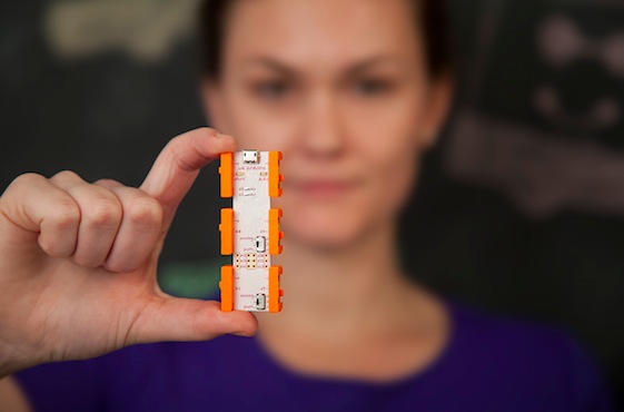
There’s a new Arduino At Heart: littleBits Arduino Module!

We are excited to announce that littleBits joined the Arduino At Heart Program to easily incorporate programming into littleBits circuits!

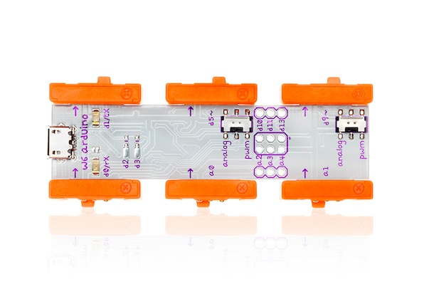
littleBits Arduino Module is everything you know and love about Arduino without the breadboarding, soldering or wiring.  littleBits takes care of the electronics, while you focus on the code.

The new littleBits Arduino Module allows to:

• Create code using the Arduino programming environment
• Communicate with software (Processing, MaxMSP, Flash etc…)
• Play with 3 inputs and 3 outputs using littleBits bitSnap™ magnetic connector as well as additional I/O for advanced hardware interaction
• Getting started with 10 sketches, including Analog Pong, Tone Libraries and more!
• Access to Arduino AND littleBits community support

Inventing on this platform requires the user to be able to debug through electronics issues as well as software bugs.
For example, instead of having to solder together a complete circuit of power, ground, resistors and LEDs, a user can simply snap a power and an LED module to the Arduino module and dive straight into programming. This will make hardware innovation even more friendly for beginners, and further lower the entry to physical computation.

Take a look at the video and discover what  you could do with it!


Easily test and experiment with GSM modules using AT Command Tester

Introduction

Working with GSM modules and by extension Arduino GSM shields can either be a lot of fun or bring on a migraine. This is usually due to the quality of module, conditions placed on the end user by the network, reception, power supply and more.

Furthermore we have learned after several years that even after following our detailed and tested tutorials, people are having trouble understanding why their GSM shield isn’t behaving. With this in mind we’re very happy to have learned about a free online tool that can be used to test almost every parameter of a GSM module with ease – AT Command Tester. This software is a Java application that runs in a web browser, and communicates with a GSM module via an available serial port.

Initial Setup

It’s simple, just visit http://m2msupport.net/m2msupport/module-tester/ with any web browser that can run Java. You may need to alter the Java security settings down to medium. Windows users can find this in Control Panel> All Control Panel Items  > Java – for example:

Once the security settings have been changed, just visit the URL, click ‘accept’ and ‘run’ in the next dialogue box that will appear, for example:

And after a moment, the software will appear:

Once you’re able to run the AT Command Tester software, the next step is to physically connect the hardware. If you’re just using a bare GSM module, a USB-serial adaptor can be used for easy connection to the PC. For Arduino GSM shield users, you can use the Arduino as a bridge between the shield and PC, however if your GSM shield uses pins other than D0/D1 for serial data transmission (such as our SIM900 shield) then you’ll need to upload a small sketch to bridge the software and hardware serial ports, for example:

//Serial Relay – Arduino will patch a serial link between the computer and the GPRS Shield
//at 19200 bps 8-N-1 Computer is connected to Hardware UART
//GPRS Shield is connected to the Software UART

#include <SoftwareSerial.h>

SoftwareSerial mySerial(7,8); // change these paramters depending on your Arduino GSM Shield

void setup()
{
  Serial.begin(19200);
  //Serial.println(“Begin”);
  mySerial.begin(19200);

}

void loop()
{
  if (mySerial.available())
    Serial.write(mySerial.read());
  if (Serial.available())
    mySerial.write(Serial.read());
}

Using the software

Once you have the hardware connected and the Arduino running the required sketch, run the software – then click “Find ports” to select the requried COM: port, set the correct data speed and click “Connect”. After a moment the software will interrogate the GSM module and report its findings in the yellow log area:

 As you can see on the left of the image above, there is a plethora of options and functions you can run on the module. By selecting the manufacturer of your GSM module form the list, a more appropriate set of functions for your module is displayed.

When you click a function, the AT command sent to the module and its response is shown in the log window – and thus the magic of this software. You can simply throw any command at the module and await the response, much easier than looking up the commands and fighting with terminal software. You can also send AT commands in batches, experiment with GPRS data, FTP, and the GPS if your module has one.

To give you a quick overview of what is possible, we’ve made this video which captures us running a few commands on a SIM900-based Arduino shield. If possible, view it in 720p.

Conclusion

Kudos to the people from the M2Msupport website for bringing us this great (and free) tool. It works – so we’re happy to recommend it. And if you enjoyed this article, or want to introduce someone else to the interesting world of Arduino – check out my book (now in a third printing!) “Arduino Workshop”.

Have fun and keep checking into tronixstuff.com. Why not follow things on twitterGoogle+, subscribe  for email updates or RSS using the links on the right-hand column, or join our forum – dedicated to the projects and related items on this website. Sign up – it’s free, helpful to each other –  and we can all learn something.

The post Easily test and experiment with GSM modules using AT Command Tester appeared first on tronixstuff.

Easily test and experiment with GSM modules using AT Command Tester

Introduction

Working with GSM modules and by extension Arduino GSM shields can either be a lot of fun or bring on a migraine. This is usually due to the quality of module, conditions placed on the end user by the network, reception, power supply and more.

Furthermore we have learned after several years that even after following our detailed and tested tutorials, people are having trouble understanding why their GSM shield isn’t behaving. With this in mind we’re very happy to have learned about a free online tool that can be used to test almost every parameter of a GSM module with ease – AT Command Tester. This software is a Java application that runs in a web browser, and communicates with a GSM module via an available serial port.

Initial Setup

It’s simple, just visit http://m2msupport.net/m2msupport/module-tester/ with any web browser that can run Java. You may need to alter the Java security settings down to medium. Windows users can find this in Control Panel> All Control Panel Items  > Java – for example:

Once the security settings have been changed, just visit the URL, click ‘accept’ and ‘run’ in the next dialogue box that will appear, for example:

And after a moment, the software will appear:

Once you’re able to run the AT Command Tester software, the next step is to physically connect the hardware. If you’re just using a bare GSM module, a USB-serial adaptor can be used for easy connection to the PC. For Arduino GSM shield users, you can use the Arduino as a bridge between the shield and PC, however if your GSM shield uses pins other than D0/D1 for serial data transmission (such as our SIM900 shield) then you’ll need to upload a small sketch to bridge the software and hardware serial ports, for example:

//Serial Relay – Arduino will patch a serial link between the computer and the GPRS Shield
//at 19200 bps 8-N-1 Computer is connected to Hardware UART
//GPRS Shield is connected to the Software UART

#include <SoftwareSerial.h>

SoftwareSerial mySerial(7,8); // change these paramters depending on your Arduino GSM Shield

void setup()
{
  Serial.begin(19200);
  //Serial.println(“Begin”);
  mySerial.begin(19200);

}

void loop()
{
  if (mySerial.available())
    Serial.write(mySerial.read());
  if (Serial.available())
    mySerial.write(Serial.read());
}

Using the software

Once you have the hardware connected and the Arduino running the required sketch, run the software – then click “Find ports” to select the requried COM: port, set the correct data speed and click “Connect”. After a moment the software will interrogate the GSM module and report its findings in the yellow log area:

 As you can see on the left of the image above, there is a plethora of options and functions you can run on the module. By selecting the manufacturer of your GSM module form the list, a more appropriate set of functions for your module is displayed.

When you click a function, the AT command sent to the module and its response is shown in the log window – and thus the magic of this software. You can simply throw any command at the module and await the response, much easier than looking up the commands and fighting with terminal software. You can also send AT commands in batches, experiment with GPRS data, FTP, and the GPS if your module has one.

To give you a quick overview of what is possible, we’ve made this video which captures us running a few commands on a SIM900-based Arduino shield. If possible, view it in 720p.

Conclusion

Kudos to the people from the M2Msupport website for bringing us this great (and free) tool. It works – so we’re happy to recommend it. And if you enjoyed this article, or want to introduce someone else to the interesting world of Arduino – check out my book (now in a third printing!) “Arduino Workshop”.

Have fun and keep checking into tronixstuff.com. Why not follow things on twitterGoogle+, subscribe  for email updates or RSS using the links on the right-hand column, or join our forum – dedicated to the projects and related items on this website. Sign up – it’s free, helpful to each other –  and we can all learn something.

Arduino and KTM-S1201 LCD modules

Learn how to use very inexpensive KTM-S1201 LCD modules in this edition of our Arduino tutorials. This is chapter forty-nine of a series originally titled “Getting Started/Moving Forward with Arduino!” by John Boxall – A tutorial on the Arduino universe. The first chapter is here, the complete series is detailed here.

Introduction

After looking for some displays to use with another (!) clock, I came across some 12-digit numeric LCD displays. They aren’t anything flash, and don’t have a back light –  however they were one dollar each. How could you say no to that? So I ordered a dozen to try out. The purpose of this tutorial is to show you how they are used with an Arduino in the simplest manner possible.

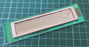
Moving forward – the modules look like OEM modules for desktop office phones from the 1990s:

With a quick search on the Internet you will find a few sellers offering them for a dollar each. The modules (data sheet) use the NEC PD7225 controller IC (data sheet):

They aren’t difficult to use, so I’ll run through set up and operation with a few examples.

Hardware setup

First you’ll need to solder some sort of connection to the module – such as 2×5 header pins. This makes it easy to wire it up to a breadboard or a ribbon cable:

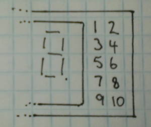
The rest of the circuitry is straight-forward. There are ten pins in two rows of five, and with the display horizontal and the pins on the right, they are numbered as such:

Now make the following connections:

  • LCD pin 1 to 5V
  • LCD pin 2 to GND
  • LCD pin 3 to Arduino D4
  • LCD pin 4 to Arduino D5
  • LCD pin 5 to Arduino D6
  • LCD pin 6 to Arduino D7
  • LCD pin 7 – not connected
  • LCD pin 8 – Arduino D8
  • LCD pin 9 to the centre pin of a 10k trimpot – whose other legs connect to 5V and GND. This is used to adjust the contrast of the LCD.

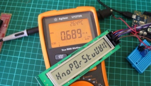
The Arduino digital pins that are used can be changed – they are defined in the header file (see further on). If you were curious as to how low-current these modules are:

That’s 0.689 mA- not bad at all. Great for battery-powered operations. Now that you’ve got the module wired up, let’s get going with some demonstration sketches.

Software setup

The sketches used in this tutorial are based on work by Jeff Albertson and Robert Mech, so kudos to them – however we’ve simplified them a little to make use easier. We’ll just cover the functions required to display data on the LCD. However feel free to review the sketches and files along with the controller chip datasheet as you’ll get an idea of how the controller is driven by the Arduino.

When using the LCD module you’ll need a header file in the same folder as your sketch. You can download the header file from here. Then every time you open a sketch that uses the header file, it should appear in a tab next to the main sketch, for example:

There’s also a group of functions and lines required in your sketch. We’ll run through those now – so download the first example sketch, add the header file and upload it. Your results should be the same as the video below:

So how did that work? Take a look at the sketch you uploaded.  You need all the functions between the two lines of “////////////////////////” and also the five lines in void setup(). Then you can display a string of text or numbers using

ktmWriteString();

which was used in void loop(). You can use the digits 0~9, the alphabet (well, what you can do with 7-segments), the degrees symbol (use an asterix – “*”) and a dash (use  – “-“). So if your sketch can put together the data to display in a string, then that’s taken care of.

If you want to clear the screen, use:

ktmCommand(_ClearDsp);

Next – to individually place digits on the screen, use the function:

tmPrnNumb(n,p,d,l);

Where n is the number to be displayed (zero or a positive integer), p is the position on the LCD for the number’s  (the positions from left to right are 11 to 0…), d is the number of digits to the right of the decimal point (leave as zero if you don’t want a decimal point), and l is the number of digits being displayed for n. When you display digits using this function you can use more than one function to compose the number to be displayed – as this function doesn’t clear the screen.

To help get your head around it, the following example sketch (download) has a variety of examples in void loop(). You can watch this example in the following video:

Conclusion

So there you have it – an incredibly inexpensive and possibly useful LCD module. Thank you to Jeff Albertson and Robert Mech for their help and original code.

In the meanwhile have fun and keep checking into tronixstuff.com. Why not follow things on twitterGoogle+, subscribe  for email updates or RSS using the links on the right-hand column? And join our friendly Google Group – dedicated to the projects and related items on this website. Sign up – it’s free, helpful to each other –  and we can all learn something.

The post Arduino and KTM-S1201 LCD modules appeared first on tronixstuff.