Posts with «wifi» label

21st Century Cheating: WiFi In A Calculator

Obviously, we would never endorse cheating on an exam, but sometimes a device is just too tempting to be left untouched. For [Neutrino], it was an old Casio calculator that happened to have a perfectly sized solar panel to fit a 128×32 OLED as replacement. But since the display won’t do much on its own, he decided to connect it to an ESP8266 and mount it all inside the calculator’s housing, turning it into a spy-worthy, internet-connected cheating device, including a stealthy user interface controlled by magnets instead of physical buttons. (Video, embedded below.)

To achieve the latter, [Neutrino] added two Hall effect sensors and a reed switch inside each end of the calculator. Placing a magnet — possibly hidden in a pen cap — near the reed switch will turn the display on, and placing another magnet near the Hall-effect sensors will navigate through the display’s interface, supporting two inputs with long, short, and multi-tap gestures each. To obtain information through WiFi, the ESP8266 connects to Firebase as backend, allowing to set up predefined content to fetch, as well as a possibility to communicate with your partner(s) in crime through a simple chat program.

As the main idea was to keep visible modifications to a minimum, one shortcoming is that charging the additional battery that powers the whole system would require an additional, external charging circuit. But [Neutrino] had a solution for that as well, and simply exposed two wires to the back, which could easily be mistaken for random solder splatters. And well, of course, requiring WiFi might also be tricky in some situations, so maybe you might want to consider a mobile network upgrade for yourself.

Hack a Day 07 May 12:00

Maker Display to Ubidots MQTT button


See the original project on the ArduinoBasics Blog


Description

This tutorial will show you how to create a simple MQTT connection to Ubidots. You will also learn to configure the necessary MQTT subscription to a button on the Ubidots dashboard, and control a Maker Display (ESP-12E compitible board) from anywhere in the world. The process may seem a bit daunting at first, but hopefully by the end of this tutorial, you will feel comfortable creating your own Ubidots MQTT subscriptions.


Parts Required

  1. Maker Display 2 or Node MCU (ESP-12E) module
  2. NOVA programmer
  3. USB mini-B cable
  4. WiFi internet connection
  5. Ubidots account (free)

The Maker display 2 has an inbuilt ESP8266MCD WiFi module which will be used to create the MQTT connection to the Ubidots broker (online).


Ubidots Setup

This tutorial requires a FREE Ubidots account.
Go to this site to sign up: https://ubidots.com/education/
Once signed up, you will need to configure Ubidots using the following instructions.

Create a device

  1. Select: Devices > Devices
  2. Select: Create a Device (button)
  3. Select: Blank (from the available device list)
  4. Enter the "Maker Display" into the "Device name" field, "maker-display" into the "Device label" field, and click on "Create" button
  5. Select: the "Maker Display" device

Create a variable

  1. Select: "Add Variable" button, then select "Raw" from the two available options.
  2. Select: the "New Variable" to edit it
  3. Change the name to "Button 1", the description to "button1 variable" and the API label to "button1"

Create a dashboard

  1. Select: Data > Dashboard
  2. Select: Add new dashboard
  3. Change the Name to "Maker Display Dashboard", and update the date format to a suitable format. (press tick)

Add a Widget

  1. Select: "Add new Widget"
  2. Select: Switch (from the available widgets)
  3. Select: Add Variables
  4. Select: Maker Display > Button1 > tick
  5. Accept the default values for the Switch (Off=0, On=1), and press the tick
  6. You should now have a button called "Button1" associated with the "Maker Display" device, visible on the "Maker Display Dashboard"
  7. The button is "off".

Create a Ubidots TOKEN

  1. Select: "API Credentials" from the profile drop-down box in the top right corner.
  2. Click the blue "More" - located below the Tokens section
  3. Click on the round blue (+) button to create a NEW TOKEN.
  4. Change the name to "Maker Display Token" - and keep a record of TOKEN value. There is an icon which will allow you copy the TOKEN value to the clipboard.

Take note of key information

Now that the Ubidots Dashboard is set up, you will need to ensure you have 3 sets of information to insert into the code.

  1. Maker Display Token Value
  2. Button1 API label: "button1"
  3. Maker Display Device API Label: "maker-display"


Ubidots slideshow of the setup process

Slide Set created by Scott C with GoConqr


Arduino IDE

While there are many Arduino IDE alternatives out there, I would recommend that you use the official Arduino IDE for this project. I used the official Arduino IDE app (v1.8.5) for Windows 10.
Make sure to get the most up-to-date version for your operating system here.

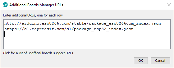
Additional Boards Manager URLS

Make sure to add the following URLs to your "additional boards manager URL" setting:
  • File > Preferences > Additional Boards Manager URLS:
    • http://arduino.esp8266.com/stable/package_esp8266com_index.json
    • https://dl.espressif.com/dl/package_esp32_index.json

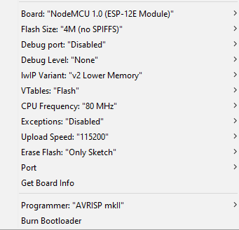
Select Tools > Board: "NodeMCU 1.0 (ESP-12E Module)" board.
Then check that you have the following settings:

  • Board:"NodeMCU 1.0 (ESP-12E Module)"
  • Flash Size:"4M(no SPIFFS)"
  • Debug port:"Disabled"
  • Debug Level:"None"
  • IwIP Variant:"v2 Lower Memory"
  • VTables:"Flash"
  • CPU Frequency:"80 MHz"
  • Exceptions:"Disabled"
  • Upload Speed:"115200"
  • Erase Flash:"Only Sketch"
  • Port: (Select your port)
  • Get Board Info
  • Programmer:"AVRISP mkII"


Libraries required

This tutorial makes use of two libraries: ESP8266WiFi.h and PubSubClient.h.

  • ESP8266WiFi.h : This library is required for the WiFi connection to the internet. More info.
  • PubSubClient.h : Is used to create an MQTT Client to handle the communication between the Ubidots MQTT broker and the Maker Display2 (or ESP-12E).

Both libraries can be installed via the library manager: Sketch > Include library > Manage Libraries


Arduino Code

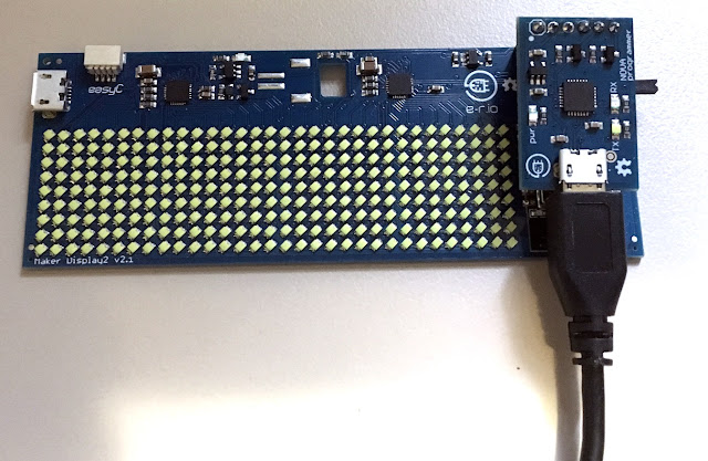
Connect the NOVA programmer to the Maker Display 2

Remember that you will need to insert the 3 bits of information from the "Ubidots" section, into the code. You will also need to know your WiFI SSID name, and password. Copy the code below into the Arduino IDE, make the necessary changes in the sketch to reflect the API labels and tokens from your Ubidots account. Connect the USB cable to the computer, select the correct COM port (Tools > Port), then upload the code to the Maker display board.

The code is available on my GitHub repository. Or you can have a look at the fully commented code below.


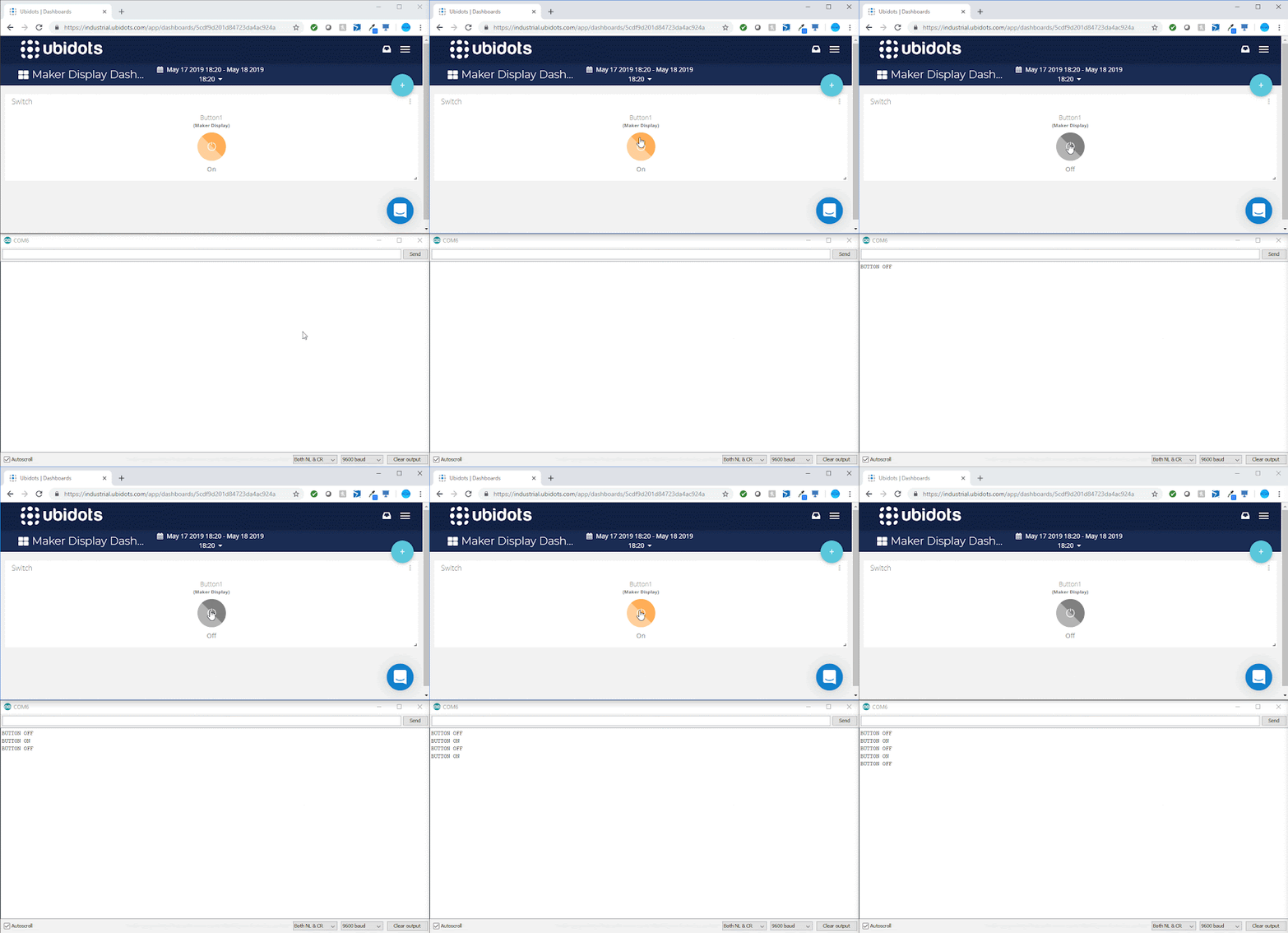
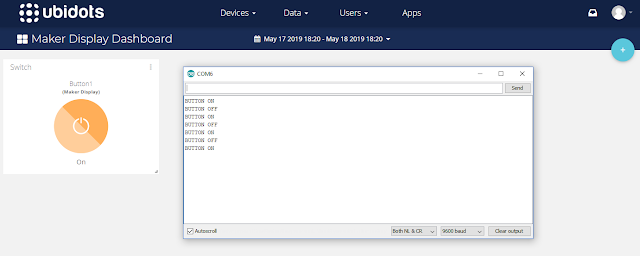
Open the Serial monitor (ctrl + shift + M), ensure the Baud is set to 9600, and then press the button on the Ubidots Maker Display Dashboard. You should see messages appear in the Serial monitor that correspond with the state of the button.


Code Explained

A number of different information sources were utilised to construct the code above. These sources were acknowledged within. As noted before, the code uses two libraries, one to simplify the WiFi connection to the internet, and the other to simplify the connection of the Maker Display to the Ubidots MQTT broker.

setup()

The setup() function is used to establish the WiFi connection, set the MQTT broker, and define the callback function - which will be called each time the button on the Ubidots dashboard is pressed.

loop()

The loop() function is responsible for connecting to the MQTT broker, and polling for messages from the MQTT broker using the client.loop() function.

callback()

The callback() function first checks the "topic" message coming from the MQTT broker, and compares it to the buttonTopic variable. The buttonTopic variable in this sketch is equal to "/v1.6/devices/maker-display/button1/lv". You will notice that the variable is constructed using the "device API label", and the "button API label". The other components of the buttonTopic are always the same. eg.

"/v1.6/devices/{device label}/{variable label}/lv"

This comparison allows us to differentiate this particular button from other potential components on the Ubidots dashboard. The value of the button (on=1/off=0), is transmitted from the MQTT broker each time the button is pressed on the Ubidots Maker Display dashboard. It is captured by the "payload" variable in the callback function. If the payload variable is equal to 1 (on), then a Serial message will be transmitted "BUTTON ON". If the payload variable is equal to 0 (off), then a Serial message will be transmitted "BUTTON OFF". You will be able to see this message come through by opening the Serial Monitor (ctrl+shift+M) within the Arduino IDE.

MQTTconnect()

The MQTTconnect() function is responsible for connecting to the MQTT broker. It requires a Ubidots TOKEN, a unique MQTT client name and a pre-defined port (1883). In order to receive messages from the button on the Ubidots Maker Display dashboard, we need to subscribe to button. But first we need to construct the string location of the button variable.  
 
We do this using the sprintf() function.  
 
If you would like to learn more about the sprintf function have a look at my tutorial here.  
 
The sprintf function is used to construct the string in a specific format, and in this case it uses the DEVICE_LABEL, and VARIABLE_LABEL1, and assigns the string to the buttonTopic variable. Once constructed the buttonTopic variable is used to subscribe to the button on the Ubidots dashboard.

The program is instructed to retry the connection attempt every 2 seconds if it fails to connect for any reason.


Project in Action


Conclusion

Setting up the Ubidots dashboard and the Arduino IDE takes up the majority of the time in this project. Once all the configurations are made, the rest is pretty simple. I hope by the end of this tutorial, you will have learnt how to create a button on a Ubidots dashboard, and interface it with a Maker Display (ESP-12 compatible board).

While there are plenty of examples on the Ubidots website that will show you how to push data to the dashboard, I found that the opposite was not true. There are limited examples that show you how to control your device from a Ubidots widget. I know that this example is not that exciting, but hopefully, you understand the significance of the information, and understand how easy it would be to modify the sketch above to make it more exciting. However, I did not want to over-complicate the tutorial with other complexities. Perhaps in the next tutorial we will use the information gained here, to do something a bit more thrilling. But at least now you know the basics. We can now:

  • Program a Maker Display
  • Add widgets to a Ubidots dashboard
  • Control the Maker Display using widgets from a Ubidots dashboard (using MQTT)

If you found this tutorial helpful, please consider supporting me by buying me a virtual coffee/beer.

$3.00 AUD only
 

Social Media

You can find me on various social networks:

Follow me on Twitter: ScottC @ArduinoBasics.
I can also be found on Instagram, Pinterest, and YouTube.
And if all else fails, I have a server on Discord.


Library Makes ESP Over the Air Updates Easy

Potentially, one of the great things about having a device connected to the network is that you can update it remotely. However, how do you make that happen? If you use the Arduino setup for the ESP8266 or ESP32, you might try [scottchiefbaker’s] library which promises to make the process easy.

Adding it looks to be simple. You’ll need an include, of course. If you don’t mind using port 8080 and the path /webota, you only need to call handle_webota() from your main loop. If you want to change the defaults, you’ll need to add an extra call in your setup. You also need to set up a few global variables to specify your network parameters.

The only caveat is that long delay statements in your loop can block things from working and aren’t a great idea anyway. If you have them, you can replace all your delay calls with webota_delay which will stop the system from ignoring update requests.

The code started from a different online tutorial but packaged the code up nicely for reuse. To do an update, simply navigate to the device with a web browser and use the correct port number and path. From there you can upload a new binary image taken from the Arduino IDE with the export compiled binary command.

The only concern we saw was the code didn’t appear to authenticate you at all. That means anyone could load code into your ESP. That might be ok on a private network, but on the public Internet it is surely asking for trouble. The original tutorial code did have a hardcoded user and password, but it didn’t look very useful as the password was in the clear and didn’t stop you from uploading if you knew the right URL. Dropping it from the library probably makes sense, but we would want to build some kind of meaningful security into anything we deployed.

If you have a network connection, we’ve seen the same trick done with a normal Arduino with a wireless chip. You can even do it over WiFi but using an ESP8266 which you’ll then want to be able to update, too.

Hack a Day 21 Mar 09:00

Badland Brawler Lets Arduino Tackle Terrain

For an electronics person, building the mechanics of a robot — especially a robust robot — can be somewhat daunting. [Jithin] started with an off-the-shelf 4 wheel drive chassis to build an off-road Arduino robot he calls the Badland Brawler. The kit was a bit over $100, but as you can see in the video below, it is pretty substantial, with an enclosed frame and large mud tires.

The remaining parts include an Arduino, a battery, and a motor driver IC. The Arduino is one with WiFi (an MKR 1000, in fact) and there’s a phone app for controlling the robot.

Honestly, once you have the chassis taken care of, the rest is pretty easy. Of course, the phone app is a bit more effort, but you could replace it in a number of ways. Blynk, comes to mind, for example.

The motor drivers are easy to figure out. This would be a great platform for some sensors to allow for more autonomy. We liked how the frame had mount points for a lot of different boards and sensors and could hold everything, for the most part, inside. That’s probably a good idea for a robot which will be traversing rugged terrain.

If you do decide to roll your own app with Blynk, we’ve done it with a very different kind of robot. Four-wheel drive robots don’t have to be big, as we’ve seen in the past.

ESP-13 WiFi Shield Web Server

Description

This tutorial will show you how to setup a simple webserver on your ESP-13 WiFi Shield and display a table of all of the WiFi Access Points within it's range (and refreshed every 5 seconds).
The ESP-13 shield will create it's own WiFi access point, which means that you can take this project anywhere you want to. You do not have to be connected to your home/work WiFi network to see the webpage. The limitation however, is that your device must be within WiFi range of the ESP-13 WiFi shield in order to see the results of the WiFi scan.

Let me show you how to put this project together:
COMING SOON....

ScottC 16 Sep 18:13

Getting Started with the Keyes ESP-13 WiFi Shield

Description

This tutorial will help you get started with the KEYES ESP-13 WiFi Shield.
The ESP-13 WiFi Shield is compatible with an Arduino UNO and has the same form-factor. Essentially this shield will give your Arduino project WiFi capabilities. While it interfaces nicely with the Arduino, it can operate without it. However, if I were planning on using the shield independantly, then I probably would opt for an ESP module rather than a shield.
I bought my shield from Jaycar (CAT.NO: XC4614), however you can get it much cheaper from other online retailers at about a quarter of the price. The instructions on the Jaycar website are not that good, and at first I thought I had bought myself a useless product. It just didn't seem to work regardless of what I tried. There were some tutorials online that gave me hope, only to find that my shield was not quite the same and therefore I did not get the same results. But after countless hours of trial and error and patching various bits of knowledge together, I finally worked out how to use this shield. Everything has fallen into place. And it is easier that you would think... let me show you how.


Coming soon......................

Getting Started with the Keyes ESP-13 WiFi Shield

Description

This tutorial will help you get started with the KEYES ESP-13 WiFi Shield.

The ESP-13 WiFi Shield is compatible with an Arduino UNO and has the same form-factor. Essentially this shield will give your Arduino project WiFi capabilities. While it interfaces nicely with the Arduino, it can operate without it. However, if I were planning on using the shield independantly, then I probably would opt for an ESP module rather than a shield.

I bought my shield from Jaycar (CAT.NO: XC4614), however you can get it much cheaper from other online retailers at about a quarter of the price. The instructions on the Jaycar website are not that good, and at first I thought I had bought myself a useless product. It just didn't seem to work regardless of what I tried. There were some tutorials online that gave me hope, only to find that my shield was not quite the same and therefore I did not get the same results. But after countless hours of trial and error and patching various bits of knowledge together, I finally worked out how to use this shield. Everything has fallen into place. And it is easier that you would think... let me show you how.

Parts Required

  1. Arduino UNO (or compatible board)
  2. KEYES ESP-13 WiFi Shield - from Jaycar (Cat. No: XC4614)
  3. USB cable - to connect Arduino to Computer
  4. 4 wires: 4 x Male to Male connectors


Libraries and IDE

Arduino IDE

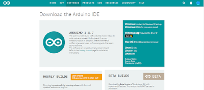
While there are many Arduino IDE alternatives out there, I would recommend that you use the official Arduino IDE for this project. I used the official Arduino IDE app (v1.8.5) for Windows 10.
Make sure to get the most up-to-date version for your operating system here.


Upload BareMinimum Sketch

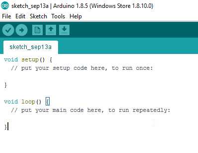
Upload a BareMinimum Sketch to the Arduino UNO (or compatible board) before making any connections to the ESP-13. We want to upload the BareMinimum sketch because we don't want the Arduino UNO interfering with our setup in anyway. Here is how to do that:

  1. Start your Arduino IDE
  2. Connect the Arduino UNO to the Computer using a USB cable
  3. Select: File > New (or Ctrl + N)
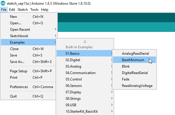
  4. Select: File > Examples > 01.Basics > BareMinimum
  5. Select: Tools > Board > Arduino/Genuino UNO
  6. Select: Tools > Port > COM4 (Your Arduino may be on a different COM port)
  7. Select: Sketch > Upload (or Ctrl + U) - or click on right arrow symbol
  8. After the sketch has uploded. Disconnect the USB cable from the computer/Arduino.


IDE Configuration for ESP-13

Now for the fun part. The ESP-13 WiFi Shield is itself a microcontroller, however, the Arduino IDE is not by default, configured to communicate with or program the ESP-13 WiFi Shield. We are about to change that:

  1. Select File > Preferences from the Arduino IDE menu (or Ctrl+Comma)
  2. Insert the following text into the Additional Boards Manager URLs field:
    If there is a URL in that space already, then insert a comma, and append the URL to the end:

    http://arduino.esp8266.com/stable/package_esp8266com_index.json


  3. Once the URL is added, press OK.
    This will allow us to install the ESP8266 package in the next step.


Installing the ESP8266 board

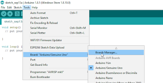
  1. Select: Tools > Board: "xxxx" > Boards Manager
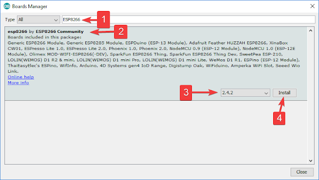
  2. Search for ESP8266 using the Search bar
  3. Select the "esp8266 by ESP8266 Community" board from the list.
  4. Select the latest or most up-to-date version from the drop-down box (eg. 2.4.2)
  5. Press the Install button.
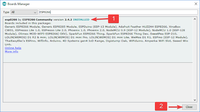
  6. Make sure that the esp8266 board is installed. Then press the "Close" button
  7. Choose the ESPDuino(ESP-13 Module) from the ESP8266 Modules list:
    Tools > Board: "xxxx" > ESPDuino(ESP-13 Module)


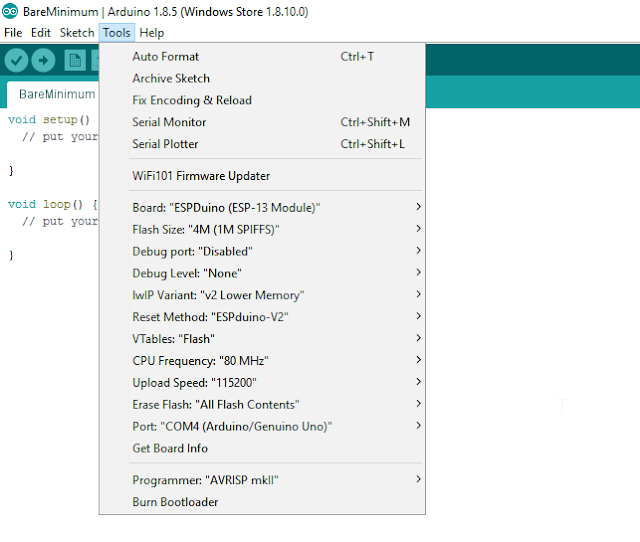
ESP-13 Flash Settings

You will then want to check that you have the following settings in the Tools menu of the Arduino IDE:

  • Board: "ESPDuino (ESP-13 Module)"
  • Flash Size: "4M (1M SPIFFS)"
  • Debug port: "Disabled"
  • Debug Level: "None"
  • IwIP Variant: "v2 Lower Memory"
  • Reset Method: "ESPduino-V2"
  • VTables: "Flash"
  • CPU Frequency: "80MHz"
  • Upload Speed: "115200"
  • Erase Flash: Only Sketch
  • Port: - (we will select that later)

The Arduino IDE is now able to communicate with, and program the ESP-13 WiFi shield.
Now let us have a look at how to use the default AI-Thinker AT-firmware that comes pre-loaded on the shield.


Preparing the WiFi Shield for Communication

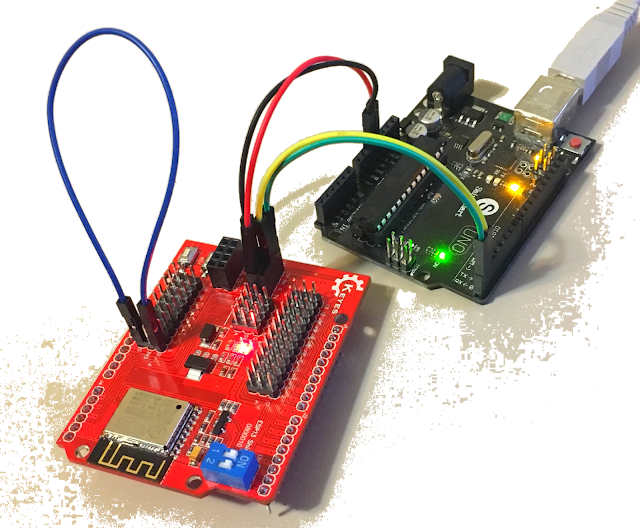
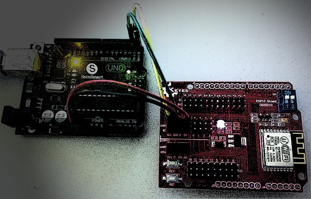
The Keyes ESP-13 WiFi shield comes pre-loaded with AI-Thinker firmware. I thought I just had to place the WiFi shield on top of the Arduino UNO, and I should be able to send through some AT commands via the Serial monitor. Yes - it is a shield, and yes, we will use it as a shield later on, but if you want to use the Serial monitor while the shield is sitting on-top of the Arduino UNO, you will need to make use of the SoftwareSerial library. You can go down this path, but it is cumbersome. There is a better way. We will still need the Arduino UNO, but we need to connect it to the ESP-13 Shield in the following manner:

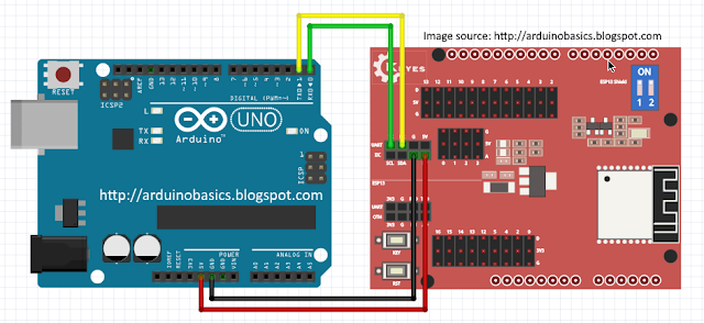
Wire Connections

  1. Make sure that the Arduino UNO is OFF (i.e. not connected to power or USB port)
  2. Place the ESP-13 WiFi shield NEXT TO the Arduino UNO
  3. Connect a Red wire between 5V on Arduino UNO, and 5V (Arduino side) of the ESP-13 shield
  4. Connect a Black wire between GND on Arduino, and G (Arduino side) of the ESP-13 shield
  5. Connect a Green wire between D0(RX) on Arduino, and TX (UART - Arduino side) of ESP-13
  6. Connect a Yellow wire between D1(TX) on Arduino, and RX (UART - Arduino side) of ESP-13
  7. Make sure that both of the switches on the ESP-13 WiFi Shield are in the "ON" position.

Serial Monitor Setup

  1. Plug the USB cable into the computer, and the other end into the Arduino
  2. You should see a Red LED ignite on the ESP-13 Shield.
  3. In your Arduino IDE, make sure the correct COM port is selected:
    Tools > Port > COM4 (Arduino/Genuino UNO) - your port may be different.
  4. The IDE recognises that an Arduino is using that COM port, even though ESP-13 Board selected
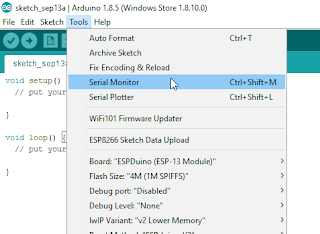
  5. Open the Serial Monitor: Tools > Serial Monitor (or Ctrl + Shift + M)
  6. Select: Both NL & CR from the drop-down box at the bottom right side of the Serial Monitor.
  7. Select: 115200 baud from the other drop-down box in the Serial Monitor window.
  8. Press the RESET (RST) button on the bottom left of the ESP-13 WiFi Shield.
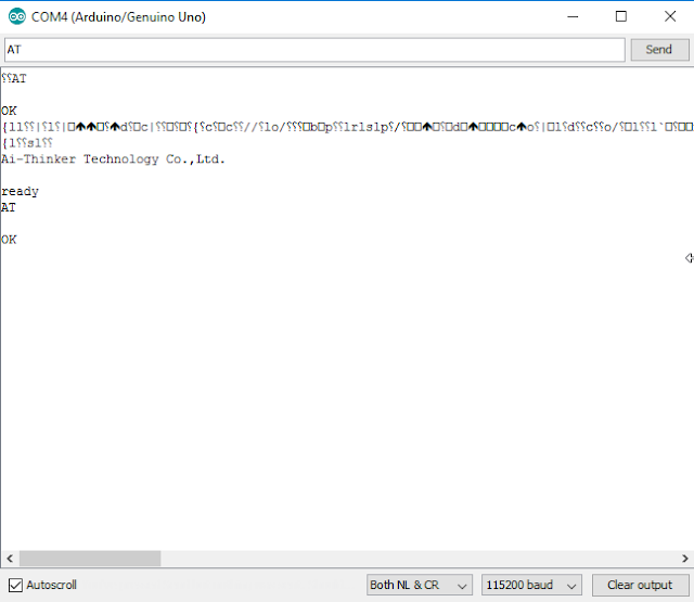
  9. You may see some garbled information come through, but you should see "Ai-Thinker Technology Co.,Ltd" and "ready" messages in the debug window.
  10. You can now send through your AT-commands to the ESP-13 WiFi shield.


Using default AI-Thinker AT-firmware

Now is a good time to test the AI-Thinker AT-firmware. It is possible to program the Arduino to send a sequence of AT commands to the ESP-13 WiFi Shield, but for demonstration purposes, I will show you how to send the commands manually via the Serial monitor.

  1. If you see "ready" within the Serial Monitor window, the ESP-13 is ready to receive AT commands.
  2. Type: AT into the box at the top and press the Send button (or Enter)
  3. You should now see the AT command in the debug window, and a response "OK"

If you received the OK message, then your communication with the ESP-13 was successful.
A good list of AT commands and explanations can be found here.
Another list of AT commands can be found here.

The commands allow you to test, query and configure the ESP-13 shield. Essentially a command-line interface. Try out the following commands to get a feel for these functions/queries. The commands are in bold, and I placed some of the responses that I got in the line below.

  1. AT
    Response: OK

  2. AT+RST
    This resets the ESP-13 board. It provides some info about the board.

  3. AT+GMR
    AT version: 0.40.0.0 (Aug 8 2015)
    SDK version: 1.3.0
    Ai-Thinker Technology Co.,Ltd.
    Build:1.3.0.2 Sep 11 2015

  4. AT+CIFSR
    +CIFSR:APIP, "192.168.4.1"

  5. AT+CWMODE?
    +CWMODE:2 [1=STA, 2=AP, 3=BOTH]

  6. AT+CWLAP
    ERROR

  7. AT+CWMODE=3

  8. AT+CWLAP
    +CWLAP:(3,"MYACCESSPOINT", -53, "xx:xx:xx:xx:xx:xx",6,-12)

So there you go. Now you have everything need to configure your ESP-13 WiFi shield. Once you are tired of playing around with AT commands, I will show you how to re-program and upload sketches to the ESP-13 WiFi Shield, and use it the way it was designed to be used (i.e. as a shield). To upload sketches to the Shield, you will need one extra wire. But I think that deserves to be another tutorial. Stay tuned.

Summary

In this tutorial, I showed you how to configure your Arduino IDE for the ESP-13 shield. I also explained how to wire the ESP-13 WiFi shield so that you can communicate with it using the Serial monitor. I hope this tutorial helped you in some way. If it did, please let me know in the comments below. I will be following up with another tutorial, which will show you how to upload sketches to the ESP-13 WiFi Shield, and free it from your computer.


Social Media

You can find me on various social networks:


Visit my ArduinoBasics Google + page.
Follow me on Twitter by looking for ScottC @ArduinoBasics.
I can also be found on Pinterest and Instagram.
Have a look at my videos on my YouTube channel.


Tubby Bot a Wifi/Smartphone controlled two wheeled bot – STEP BY STEP GUIDE

Let's Make Robots 05 Jul 20:09
arduino  esp8266  wifi  

More Blinky = More Better – The WS2812FX Library

The WS2812 is an amazing piece of technology. 30 years ago, high brightness LEDs didn’t even exist yet. Now, you can score RGB LEDs that even take all the hard work out of controlling and addressing them! But as ever, we can do better.

Riffing on the ever popular Adafruit NeoPixel library, [Harm] created the WS2812FX library. The library has a whole laundry list of effects to run on your blinkenlights – from the exciting Hyper Sparkle to the calming Breathe inspired by Apple devices. The fantastic thing about this library is that it can greatly shorten development time of your garden-variety blinkables – hook up your WS2812s, pick your effect, and you’re done.

[Harm]’s gone and done the hard yards, porting this to a bevy of platforms – testing it on the Arduino Nano, Uno, Micro and ESP8266. As a proof of concept, they’ve also put together a great demonstration of the software – building some cute and stylish Christmas decorations from wood, aluminium, and hacked up Christmas light housings. Combining it with an ESP8266 & an app, the effects can be controlled from a smartphone over WiFi. The assembly video on YouTube shows the build process, using screws and nails to create an attractive frame using aluminium sheet.

This project is a great example of how libraries and modern hardware allow us to stand on the shoulders of giants. It’s quicker than ever to build amazingly capable projects with more LEDs than ever. Over the years we’ve seen plenty great WS2812 projects, like this sunrise alarm clock or this portable rave staff.
As always, blink hard, or go home. Video after the break.


Filed under: Arduino Hacks, Holiday Hacks, led hacks

adding wifi control input to a robot running Arduino

I would like to add wifi control to my robot.  Right now it uses an Arduino Mega2650 to run the main control program.  I'd like to add to this contol inputs from an Android smartphone app over Wifi.  What do you recommend to do this?