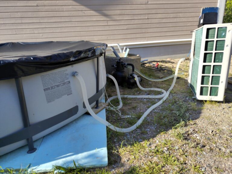
For home HVAC systems, heat pumps seem to be the way of the future. When compared to electric heating they can be three to four times more efficient, and they don’t directly burn fossil fuels. They also have a leg up over standard air conditioning systems since they can provide both cooling and heating, and they can even be used on water heating systems. Their versatility seems unmatched, but it does come at a slight cost of complexity as [Janne] learned while trying to bring one back to life.
The heat pump here is a Samsung with some physical damage, as well as missing the indoor half of the system. Once the damage to the unit was repaired and refilled with refrigerant, [Janne] used an Optidrive E3 inverter controlled by an Arduino Mega to get the system functional since the original setup wouldn’t run the compressor without the indoor unit attached. The Arduino manages everything else on the system as well including all of the temperature sensors and fan motor control.
With everything up and running [Janne] connected the system to a swimming pool, which was able to heat the pool in about three hours using 60 kWh of energy. The system is surprisingly efficient especially compared to more traditional means of heating water, and repairing an old or damaged unit rather than buying a new one likely saves a significant amount of money as well. Heat pump projects are getting more common around here as well, and if you have one in your home take a look at this project which adds better climate control capabilities. to a wall mount unit.
In this chapter we will introduce and examine the use of Ethernet networking with Arduino over local networks and the greater Internet.
It will be assumed that you have a basic understanding of computer networking, such as the knowledge of how to connect computers to a hub/router with RJ45 cables, what an IP and MAC address is, and so on. Furthermore, here is a good quick rundown about Ethernet.
Furthermore you will need to power the board via the external DC socket – the W5100 IC uses more current than the USB power can supply. A 9V 1.5A plug pack/wall wart will suffice.
Finally it does get hot – so be careful not to touch the W5100 after extended use. In case you’re not sure – this is the W5100 IC:
Once you have your Ethernet-enabled Arduino, and have the external power connected – it’s a good idea to check it all works. Open the Arduino IDE and select File > Examples > Ethernet > Webserver. This loads a simple sketch which will display data gathered from the analogue inputs on a web browser. However don’t upload it yet, it needs a slight modification.
You need to specify the IP address of the Ethernet shield – which is done inside the sketch. This is simple, go to the line:
IPAddress ip(192,168,1, 177);
And alter it to match your own setup. For example, in my home the router’s IP address is 10.1.1.1, the printer is 10.1.1.50 and all PCs are below …50. So I will set my shield IP to 10.1.1.77 by altering the line to:
IPAddress ip(10,1,1,77);
You also have the opportunity to change your MAC address. Each piece of networking equipment has a unique serial number to identify itself over a network, and this is normall hard-programmed into the equipments’ firmware. However with Arduino we can define the MAC address ourselves.
If you are running more than one Ethernet shield on your network, ensure they have different MAC addresses by altering the hexadecimal values in the line:
However if you only have one shield just leave it be. There may be the very, very, statistically rare chance of having a MAC address the same as your existing hardware, so that would be another time to change it.
Once you have made your alterations, save and upload the sketch. Now open a web browser and navigate to the IP address you entered in the sketch, and you should be presented with something similar to the following:
What’s happening? The Arduino has been programmed to offer a simple web page with the values measured by the analogue inputs. You can refresh the browser to get updated values.
At this point – please note that the Ethernet shields use digital pins 10~13, so you can’t use those for anything else. Some Arduino Ethernet shields may also have a microSD card socket, which also uses another digital pin – so check with the documentation to find out which one.
Nevertheless, now that we can see the Ethernet shield is working we can move on to something more useful. Let’s dissect the previous example in a simple way, and see how we can distribute and display more interesting data over the network. For reference, all of the Ethernet-related functions are handled by the Ethernet Arduino library. If you examine the previous sketch we just used, the section that will be of interest is:
 for (int analogChannel = 0; analogChannel < 6; analogChannel++)
          {
            int sensorReading = analogRead(analogChannel);
            client.print("analog input ");
            client.print(analogChannel);
            client.print(" is ");
            client.print(sensorReading);
            client.println("<br />");
          }
          client.println("</html>");
Hopefully this section of the sketch should be familiar – remember how we have used serial.print(); in the past when sending data to the serial monitor box? Well now we can do the same thing, but sending data from our Ethernet shield back to a web browser – on other words, a very basic type of web page.
However there is something you may or may not want to learn in order to format the output in a readable format – HTML code. I am not a website developer (!) so will not delve into HTML too much.
However if you wish to serve up nicely formatted web pages with your Arduino and so on, here would be a good start. In the interests of simplicity, the following two functions will be the most useful:
client.print(" is ");
Client.print (); allows us to send text or data back to the web page. It works in the same way as serial.print(), so nothing new there. You can also specify the data type in the same way as with serial.print(). Naturally you can also use it to send data back as well. The other useful line is:
client.println("<br />");
which sends the HTML code back to the web browser telling it to start a new line. The part that actually causes the carriage return/new line is the <br /> which is an HTML code (or “tag”) for a new line. So if you are creating more elaborate web page displays, you can just insert other HTML tags in the client.print(); statement.
If you want to learn more about HTML commands, here’s a good tutorial site. Finally – note that the sketch will only send the data when it has been requested, that is when it has received a request from the web browser.
Accessing your Arduino over the Internet
So far – so good. But what if you want to access your Arduino from outside the local network?
You will need a static IP address – that is, the IP address your internet service provider assigns to your connection needs to stay the same. If you don’t have a static IP, as long as you leave your modem/router permanently swiched on your IP shouldn’t change. However that isn’t an optimal solution.
If your ISP cannot offer you a static IP at all, you can still move forward with the project by using an organisation that offers a Dynamic DNS. These organisations offer you your own static IP host name (e.g. mojo.monkeynuts.com) instead of a number, keep track of your changing IP address and linking it to the new host name. From what I can gather, your modem needs to support (have an in-built client for…) these DDNS services. As an example, two companies are No-IP andDynDNS.com. Please note that I haven’t used those two, they are just offered as examples.
Now, to find your IP address… usually this can be found by logging into your router’s administration page – it is usually 192.168.0.1 but could be different. Check with your supplier or ISP if they supplied the hardware. For this example, if I enter 10.1.1.1 in a web browser, and after entering my modem administration password, the following screen is presented:
What you are looking for is your WAN IP address, as you can see in the image above. To keep the pranksters away, I have blacked out some of my address.
The next thing to do is turn on port-forwarding. This tells the router where to redirect incoming requests from the outside world. When the modem receives such a request, we want to send that request to the port number of our Ethernet shield. Using the:
EthernetServer server(125);
function in our sketch has set the port number to 125. Each modem’s configuration screen will look different, but as an example here is one:
So you can see from the line number one in the image above, the inbound port numbers have been set to 125, and the IP address of the Ethernet shield has been set to 10.1.1.77 – the same as in the sketch.
After saving the settings, we’re all set. The external address of my Ethernet shield will be the WAN:125, so to access the Arduino I will type my WAN address with :125 at the end into the browser of the remote web device, which will contact the lonely Ethernet hardware back home.
Furthermore, you may need to alter your modem’s firewall settings, to allow the port 125 to be “open” to incoming requests. Please check your modem documentation for more information on how to do this.
Now from basically any Internet connected device in the free world, I can enter my WAN and port number into the URL field and receive the results. For example, from a phone when it is connected to the Internet via LTE mobile data:
So at this stage you can now display data on a simple web page created by your Arduino and access it from anywhere with unrestricted Internet access. With your previous Arduino knowledge you can now use data from sensors or other parts of a sketch and display it for retrieval.
Displaying sensor data on a web page
As an example of displaying sensor data on a web page, let’s use an inexpensive and popular temperature and humidity sensor – the DHT22. You will need to install the DHT22 Arduino library which can be found on this page. If this is your first time with the DHT22, experiment with the example sketch that’s included with the library so you understand how it works.
Connect the DHT22 with the data pin to Arduino D2, Vin to the 5V pin and GND to … GND.
Now for our sketch – to display the temperature and humidity on a web page. If you’re not up on HTML you can use online services such as this to generate the code, which you can then modify to use in the sketch.
In the example below, the temperature and humidity data from the DHT22 is served in a simple web page:
#include <SPI.h>
#include <Ethernet.h>

// for DHT22 sensor
#include "DHT.h"
#define DHTPIN 2
#define DHTTYPE DHT22

// Enter a MAC address and IP address for your controller below.
// The IP address will be dependent on your local network:
byte mac[] = {   0xDE, 0xAD, 0xBE, 0xEF, 0xFE, 0xED };
IPAddress ip(10,1,1,77);

// Initialize the Ethernet server library
// with the IP address and port you want to use
// (port 80 is default for HTTP):
EthernetServer server(125);
DHT dht(DHTPIN, DHTTYPE);

void setup()
{
  dht.begin();
 // Open serial communications and wait for port to open:
  Serial.begin(9600);
   while (!Serial) {
    ; // wait for serial port to connect. Needed for Leonardo only
  }
  // start the Ethernet connection and the server:
  Ethernet.begin(mac, ip);
  server.begin();
  Serial.print("server is at ");
  Serial.println(Ethernet.localIP());
}

void loop()
{
  // listen for incoming clients
  EthernetClient client = server.available();
  if (client) {
    Serial.println("new client");
    // an http request ends with a blank line
    boolean currentLineIsBlank = true;
    while (client.connected()) {
      if (client.available()) {
        char c = client.read();
        Serial.write(c);
        // if you've gotten to the end of the line (received a newline
        // character) and the line is blank, the http request has ended,
        // so you can send a reply
        if (c == 'n' && currentLineIsBlank)
        {
          // send a standard http response header
          client.println("HTTP/1.1 200 OK");
          client.println("Content-Type: text/html");
          client.println("Connection: close");  // the connection will be closed after completion of the response
	  client.println("Refresh: 30");  // refresh the page automatically every 30 sec
          client.println();
          client.println("<!DOCTYPE HTML>");
          client.println("<html>");

          // get data from DHT22 sensor
          float h = dht.readHumidity();
          float t = dht.readTemperature();
          Serial.println(t);
          Serial.println(h);

          // from here we can enter our own HTML code to create the web page
          client.print("<head><title>Office Weather</title></head><body><h1>Office Temperature</h1><p>Temperature - ");
          client.print(t);
          client.print(" degrees Celsius</p>");
          client.print("<p>Humidity - ");
          client.print(h);
          client.print(" percent</p>");
          client.print("<p><em>Page refreshes every 30 seconds.</em></p></body></html>");
          break;
        }
        if (c == 'n') {
          // you're starting a new line
          currentLineIsBlank = true;
        }
        else if (c != 'r') {
          // you've gotten a character on the current line
          currentLineIsBlank = false;
        }
      }
    }
    // give the web browser time to receive the data
    delay(1);
    // close the connection:
    client.stop();
    Serial.println("client disonnected");
  }
}
It is a modification of the IDE’s webserver example sketch that we used previously – with a few modifications. First, the webpage will automatically refresh every 30 seconds – this parameter is set in the line:
client.println("Refresh: 30"); // refresh the page automatically every 30 sec
… and the custom HTML for our web page starts below the line:
// from here we can enter our own HTML code to create the web page
You can then simply insert the required HTML inside client.print() functions to create the layout you need.
Finally – here’s an example screen shot of the example sketch at work:
You now have the framework to create your own web pages that can display various data processed with your Arduino.
To keep up to date with new posts at tronixstuff.com, please subscribe to the mailing list in the box on the right, or follow us on twitter @tronixstuff.
Universal remotes are a handy tool to have around if you have many devices that would all otherwise have their own remote controls. Merging them all into a single device leads to less clutter and less frustration, but they are often not truly “universal” as some of them may not support every infrared device that has ever been built. If you’re in a situation like that it’s possible to build a truly universal remote instead, provided you have a microcontroller and a few infrared LEDs on hand.
This was the situation that [Matt] found himself in when his Amazon Fire TV equipment control feature didn’t support his model of speakers. To get around this he programmed an Arduino to essentially translate the IR codes from the remote and output a compatible set of codes to the speakers.This requires both an IR photodiode and an IR LED but little else other than the codes for the remote and the equipment in question. With that all set up and programmed into the Aruino, [Matt]’s remote is one step closer to being truly “universal”.
While [Matt] was able to make use of existing codes in the Arduino library, it is also possible to capture the codes required manually by pointing a remote at a photodiode and programming a microcontroller to capture the codes that you need. [Matt] used a Raspberry Pi to do this when debugging this project, but we’ve also seen this method used with a similar build which uses an ESP8266 to control an air conditioner via its infrared remote control capabilities.
While almost everyone has a heater of some sort in their home, it’s fairly unlikely that the heat provided by a central heating system such as a furnace is distributed in an efficient way. There’s little reason to heat bedrooms during the day, or a kitchen during the night, but heating systems tend to heat whole living space regardless of the time of day or the amount of use. You can solve this problem, like most problems, with an Arduino.
[Karl]’s build uses a series of radiator valves to control when each room gets heat from a boiler. The valves, with a temperature monitor at each valve, are tied into a central Arduino Mega using alarm wiring. By knowing the time of day and the desired temperature in each room, the Arduino can control when heat is applied to each room and when it is shut off, presumably making the entire system much more efficient. It also has control over the circulating pump and some of the other boiler equipment.
Presumably this type of system could be adapted to a system which uses a furnace and an air handler as well, although it is not quite as straightforward to close vents off using a central unit like this as it is to work with a boiler like [Karl] has. With careful design, though, it could be done. Besides replacing thermostats, we can’t say we’ve ever seen this done before.
There are few scenes in life more moving than the moment the solder paste melts as the component slides smoothly into place. We’re willing to bet the only reason you don’t have a reflow oven is the cost. Why wouldn’t you want one? Fortunately, the vastly cheaper DIY route has become a whole lot easier since the birth of the Reflowduino – an open source controller for reflow ovens.
This Hackaday Prize entry by [Timothy Woo] provides a super quick way to create your own reflow setup, using any cheap means of heating you have lying around. [Tim] uses a toaster oven he paid $21 for, but anything with a suitable thermal mass will do. The hardware of the Reflowduino is all open source and has been very well documented – both on the main hackaday.io page and over on the project’s GitHub.
The board itself is built around the ATMega32u4 and sports an integrated MAX31855 thermocouple interface (for the all-important PID control), LiPo battery charging, a buzzer for alerting you when input is needed, and Bluetooth. Why Bluetooth? An Android app has been developed for easy control of the Reflowduino, and will even graph the temperature profile.
When it comes to controlling the toaster oven/miscellaneous heat source, a “sidekick” board is available, with a solid state relay hooked up to a mains plug. This makes it a breeze to setup any mains appliance for Arduino control.
For a DIY reflow setup, most people seem to rely on the trusty thrift store toaster oven as a platform to hack. But there’s something to be said for heating the PCB directly rather than heating the surrounding air, and for that one can cruise the yard sales looking for a hot plate to convert. But an electric wok as a reflow hotplate? Sure, why not?
At the end of the day [ThomasVDD]’s reflow wok is the same as any other reflow build. It has a heat source that can be controlled easily, temperature sensors, and a microcontroller that can run the proportional-integral-derivative (PID) control algorithm needed for precise temperature control. That the heating element he used came from an electric wok was just a happy accident. A laser-cut MDF case complete with kerf-bent joints holds the heating element, the solid-state relay, and the Arduino Nano that runs the show. A MAX6675 thermocouple amp senses the temperature and allows the Nano to cycle the temperature through different profiles for different solders. It’s compact, simple, and [ThomasVDD] now has a spare wok to use on the stove top. What’s not to like?
[Rhonda] has multiple sclerosis (MS), a disease that limits her ability to walk and use her arms. She and the other residents of The Boston Home, an extended care facility for people with MS and other neuromuscular diseases, rely on their wheelchairs for mobility. [Rhonda]’s chair comes with a control console that swings out of the way to allow her to come up close to tables and counters, but she has problems applying enough force to manually position it.
Sadly, [Rhonda]’s insurance doesn’t cover a commercial solution to her problem. But The Boston Home has a fully equipped shop to extend and enhance residents’ wheelchairs, and they got together with students from MIT’s Principles and Practices of Assistive Technology (PPAT) course to hack a solution that’s not only useful for [Rhonda] but should be generally applicable to other chairs. The students analyzed the problem, measured the forces needed and the clearances required, and built a prototype pantograph mount for the control console. They’ve made the device simple to replicate and kept the BOM as inexpensive as possible since patients are often out-of-pocket for enhancements like these. The video below shows a little about the problem and the solution.
I came across this circuit on google. It controls motor speed by simple flip-flop that gives a PWM signal.
The question is can this be used as a servo control ?
first use 5 volts supply instead of 12 volts ...then by replacing the 3RD NPN transistor with a servo. the + goes up, the - goes down and the signal feeds from the flip flop...can we do that ??