Posts with «oled» label

Smooth Animations, Slick Bar Graphs, but No Custom Characters on This 16×2 OLED

Sometimes, finding new ways to use old hardware requires awesome feats of reverse engineering, software sleight of hand, and a healthy dose of good fortune. Other times, though, it’s just as simple as reading the data sheet and paying attention to details.

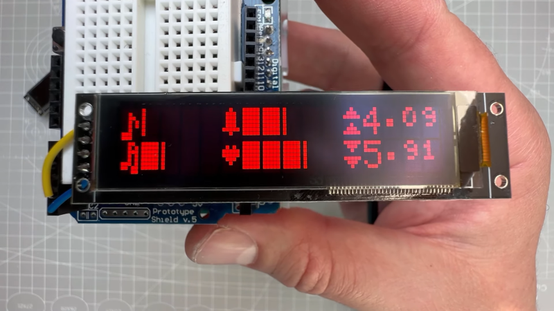
Not that we’re knocking [upir]’s accomplishment with these tricked-out 16×2 OLED displays. Far from it, in fact — the smoothly animated bar graph displays alphanumerics look fantastic. What’s cool about this is that he accomplished all this without resorting to custom characters. We’ve seen him use this approach before; this time around, the hack involves carefully shopping for a 16×2 OLED display with the right driver chip — a US2066 chip. You’ll still need a few tricks to get things working, like extra pull-up resistors to get the I2C display talking to an Arduino, plus a little luck that you got a display with the right character ROM.

Once all that is taken care of, getting the display to do what you want is mainly a matter of coding. In the video below, [upir] does a great job of walking through the finer points, and the results look great. The bar graphs in particular look fantastic, with silky-smooth animations.

Hack a Day 27 Apr 21:00
16x2  animation  arduino  display  led hacks  oled  rom  us2066  

The Great Resistor Embiggens the Smallest Value

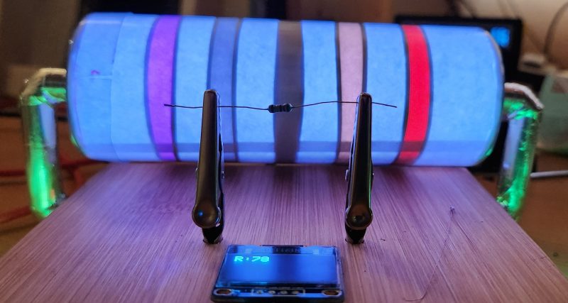
With surface-mount components quickly becoming the norm, even for homebrew hardware, the resistor color-code can sometimes feel a bit old-hat. However, anybody who has ever tried to identify a random through-hole resistor from a pile of assorted values will know that it’s still a handy skill to have up your sleeve. With this in mind, [j] decided to super-size the color-code with “The Great Resistor”.

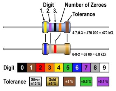
How the resistor color-code bands work

At the heart of the project is an Arduino Nano clone and a potential divider that measures the resistance of the test resistor against a known fixed value. Using the 16-bit ADC, the range of measurable values is theoretically 0 Ω to 15 MΩ, but there are some remaining issues with electrical noise that currently limit the practical range to between 100 Ω and 2 MΩ.

[j] is measuring the supply voltage to help counteract the noise, but intends to move to an oversampling/averaging method to improve the results in the next iteration.

The measured value is shown on the OLED display at the front, and in resistor color-code on an enormous symbolic resistor lit by WS2812 RGB LEDs behind.

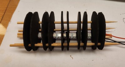
Inside The Great Resistor, the LEDs and baffle plates make the magic work

Precision aside, the project looks very impressive and we like the way the giant resistor has been constructed. It would look great at a science show or a demonstration. We’re sure that the noise issues can be ironed out, and we’d encourage any readers with experience in this area to offer [j] some tips in the comments below. There’s a video after the break of The Great Resistor being put through its paces!

If you want to know more about the history of the resistor color code bands, then we have you covered.  Alternatively, how about reading the color code directly with computer vision?

DIY Arduino Hearing Test Device

Hearing loss is a common problem for many – especially those who may have attended too many loud concerts in their youth. [mircemk] had recently been for a hearing test, and noticed that the procedure was actually quite straightforward. Armed with this knowledge, he decided to build his own test system and document it for others to use.

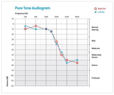
Resultant audiogram from the device showing each ear in a different color

By using an Arduino to produce tones of various stepped frequencies, and gradually increasing the volume until the test subject can detect the tone, it is possible to plot an audiogram of hearing threshold sensitivity.  Testing each ear individually allows a comparison between one side and the other.

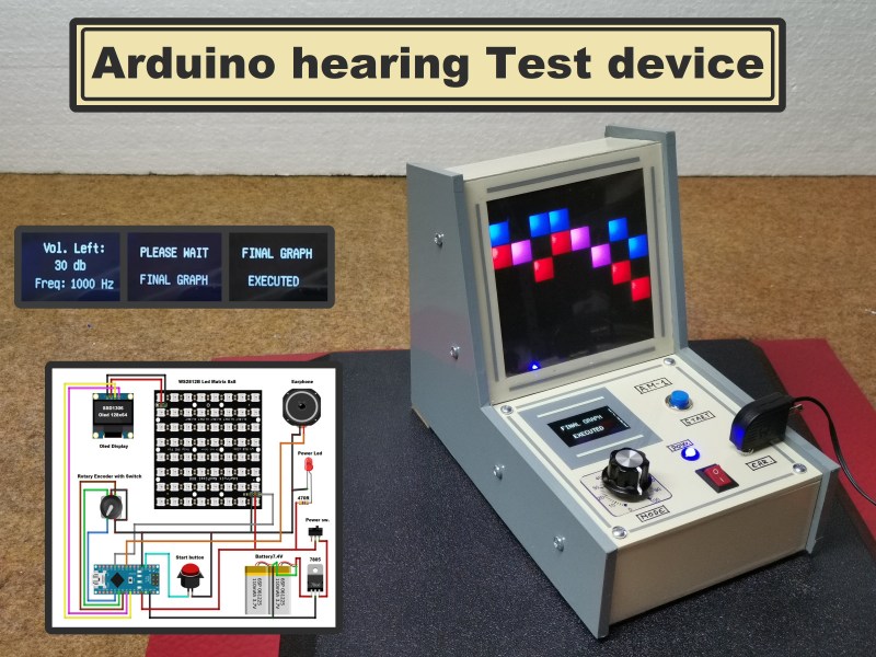
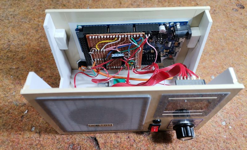
[mircemk] has built a nice miniature cabinet that holds an 8×8 matrix of WS2812 addressable RGB LEDs.  A 128×64 pixel OLED display provides user instructions, and a rotary encoder with push-button serves as the user input.

Of course, this is not a calibrated professional piece of test equipment, and a lot will depend on the quality of the earpiece used.  However, as a way to check for gross hearing issues, and as an interesting experiment, it holds a lot of promise.

There is even an extension, including a Class D audio amplifier, that allows the use of bone-conduction earpieces to help narrow down the cause of hearing loss further.

There’s some more information on bone conduction here, and we’ve covered an intriguing optical stimulation cochlear implant, too.

DIY Arduino Due TEA5767 FM Radio

Older hackers will remember that a crystal set radio receiver was often one of the first projects attempted.  Times have changed, but there’s still something magical about gathering invisible signals from the air and listening to the radio on a homemade receiver. [mircemk] has brought the idea right up to date by building an FM radio with an OLED display, controlled with a rotary encoder.

The design is fairly straightforward, based as it is on another project that [mircemk] found on a Chinese site, but the build looks very slick and would take pride of place on any hacker’s workbench. An Arduino Due forms the heart of the project, controlling a TEA5767 module, an SH1106 128×64 pixel OLED display and a rotary encoder. The sound signal is passed through an LM4811 headphone amplifier for private listening, and a PAM8403 Class D audio amplifier for the built-in loudspeaker. The enclosure is made from PVC panels, and accented with colored adhesive tape for style.

It’s easier than ever before to quickly put together projects like this by connecting pre-built modules and downloading code from the Internet, but that doesn’t mean it’s not a worthwhile way to improve your skills and make some useful devices like this one. There are so many resources available to us these days and standing on the shoulders of giants has always been a great way to see farther.

We’ve shown some other radio projects using Arduinos and the TEA5767 IC in the past, such as this one on a tidy custom PCB, and this one built into an old radio case.

Hack a Day 09 Oct 06:00

Pocket Radio Powered By Tiny Microcontroller

Before the days of MP3 players and smartphones, and even before portable CD players, those of us of a certain age remember that our cassette players were about the only way to take music on-the-go. If we were lucky, they also had a built-in radio for when the single tape exhausted both of its sides. Compared to then, it’s much easier to build a portable radio even though cassettes are largely forgotten, as [wagiminator] shows us with this radio design based on an ATtiny.

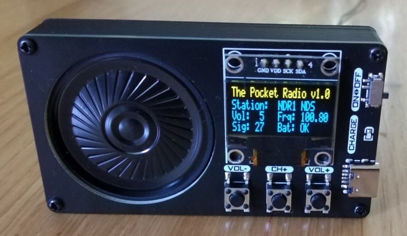
The build is about as compact as possible, with the aforementioned ATtiny 402/412 as its core, it also makes use of an integrated circuit FM tuner,  an integrated audio amplifier with its own single speaker, and a small OLED display. The unit also boasts its own lithium-polymer battery charger and its user interface consists of only three buttons, plenty for browsing radio stations and controlling volume.

The entire build fits easily in the palm of a hand and is quite capable for a mobile radio, plus all of the schematics and code is available on the project page. While it doesn’t include AM capability, just the fact that FM is this accessible nowadays when a few decades ago it was cutting-edge technology is quite remarkable. If you’re looking for an even smaller FM receiver without some of the bells and whistles of this one, take a look at this project too.

Hack a Day 06 Jul 21:00
arduino  attiny  audio  code  fm  oled  radio  radio hacks  schematics  speaker  

DIY Handheld Game Puts its Brains on a Removable Cart

Over the years we’ve seen plenty of homebrew handheld game systems that combine an AVR microcontroller, a few buttons, and an small OLED display. We’ve even seen some of them turned into commercial products, such as the Arduboy. They’re simple, cheap, and with the right software, a lot of fun. But being based on an MCU, most of them share the same limitation of only being able to hold a single game at any one time.

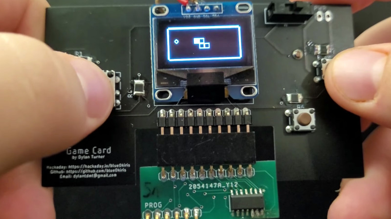
But not the Game Card, by [Dylan Turner]. This handheld was specifically designed so that games could be easily swapped out using physical cartridges. But rather than trying to get the system’s microcontroller to boot code from an external flash chip, the system relocates the MCU to the removable cartridge. That might seem a bit overkill, but given how cheap the ATTINY84A on each cartridge is, it’s not exactly going to break the bank.

With the microcontroller on the cartridge, the only hardware that stays behind on the Game Card is the SSD1306 128×64 OLED display, buttons, and the battery. That means the handheld is effectively non-functional unless a game is slotted in, but that could be said of most early cartridge-based game systems as well. On the other hand, it also opens up the possibility of producing cartridges with more powerful microcontrollers down the line.

Using a different microcontroller for each game is a neat hack, but it’s not the only solution to the problem. We previously saw a community effort to add expandable storage to the Arduboy in the form of a DIY cartridge, which ultimately led to the development of an official flash chip upgrade for the handheld.

Assembling the Pro Mini OLED clock shield kit

Customers complained about the lack of documentation on the Pro Mini OLED clock kit.

I listened and I agree. Even though the silkscreen should provide the necessary directions for soldering the parts on the shield itself, adding the Pro Mini board and the OLED display are still ambiguous, especially because there are multiple options.

Here is a quick, but hopefully adequate, step-by-step guide on one way to assemble this clock kit.

1. Make sure you source the correct Pro Mini board, that looks similar to the one in the photos below. It features an ATmega328 clocked at 16MHz.


Note that SCL and SDA (A5, A4 respectively) are broken out. Also, the FTDI connects directly to the side of the Pro Mini board.


2. Program the board itself with the OLED Clock sketch. In Tools/Board, select "Arduino Duemilanove w/ ATmega328". Upload using the FTDI adapter. This step is important because you want to make sure your Pro Mini works before you mount/solder it.

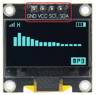
3. Make sure you source the correct I2C 128x64 OLED display, like the one shown below.


The pins at the top must be in the order (left to right) VCC-GND-SCL-SDA or VCC-GND-SDA-SCL.

In case your display has a different arrangement of the pins, e.g. GND-VCC-SCL-SDA, you will need to swap the leftmost two pins, by rewiring the traces (cut, then reconnect) on the shield's PCB (not on the display, which remains untouched), as explained in Step 6.

4. Solder the DS1307, paying attention to the correct orientation (notch up), then the 2 resistors and the crystal.

5. Solder the 2 jumper bridges according to the OLED display you are going to use.


If your OLED has pin 3 and 4 configured as SCL and SDA respectively, then solder the right bridge of the left jumper and the left bridge of the right jumper (see the photo below).


6. Only if necessary
Remember, the Pro Mini OLED shield was designed for I2C OLED displays that have pin 1 as VCC and pin 2 as GND. If that is not the case (as in the photo below),
those first 2 pins must be rewired, as shown (after the traces had been cut and pins isolated).


7. Solder the Pro Mini board on top and close to the OLED shield, using machined male pins (included in the kit). Only the relevant pins, highlighted in the photo below, need to be soldered.


Pay attention, since this is a hard-to-reverse move. Fixing a mistake here involves de-soldering. Also, the parts underneath cannot be (easily) accessed anymore.

8. Solder the 4-pin female header, the 2 buttons and the battery holder, then insert the CR1225 battery, with the correct polarity (+ on top).


9. Insert the OLED display.

10. Power the clock through the FTDI breakout (observe the correct orientation) or by directly wiring VCC and GND to a 5V or battery source.
Any of the 5 clock faces can be selected by pushing simultaneously the 2 buttons.
Pressing each button individually will increment either the hours or the minutes.


Enclosure ideas for WiFiChron and other clocks

It turns out that most electronics, even prototypes, can be easily enclosed with Lego. And that means no screws, no glue, no fasteners, zero tools, just the bricks and some imagination.

This is the HDSP clock variant with 1" displays driven by HT16K33 (introduced here). The board was cut and filed (0.5mm on each side) to fit snug between the walls (see this).


Next is a HDSP clock variant with two Adafruit Quad Alphanumeric displays.


Similarly, the PCB was cut and filed a bit. The assembly fits solidly between the bricks (no movement when shaken). As in the previous build, the exposed PCB is kind-of-required to allow access to the two buttons (set hours, set minutes).

Both of the above can be mounted on a Lego wall (as found in schools) or they can desk-stand on their own.

Here is an example of a Lego-encapsulated WifiChron.


The PCB was also filed about 0.5mm on each side to fit between the lateral brick walls. It did not have to be fastened in any other way. The ESP8266 module fits inside nicely. The 3 buttons and the USB mini B connector are all easily accessible from the back.

Below is the Lego version of the Axiris clock.


Since it does not have any buttons, the time is set through Bluetooth (command "SET TIME=hh:mm", sent from Terminal app while BT paired).

And finally, a couple of OLED clocks, both running the same software on similar hardware: pro-mini + OLED shield and wsduino + 2.42" OLED shield, respectively.


Note that this is the prototype version, using a LiPo battery with charger (similar to the one shown here).


Again, all the above enclosures feel solid: nothing moves or rattles when upside down or even shaken. I did not try dropping them though :)

And lastly, the WiFiChron with Adafruit quad 0.56" displays from the previous post, sandwiched between scrap plexiglass plates:


Parking Assistant Helps Back Up the Car Without Going Too Far

Sure, [Ty Palowski] could have just hung a tennis ball from the ceiling, but that would mean getting on a ladder, testing the studfinder on himself before locating a ceiling joist, and so on. Bo-ring. Now that he finally has a garage, he’s not going to fill it with junk, no! He’s going to park a big ol’ Jeep in it. Backwards.

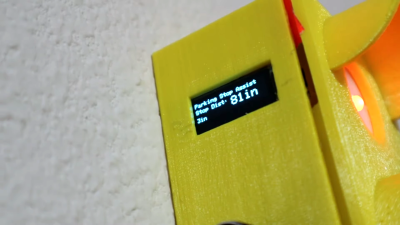
The previous owner was kind enough to leave a workbench in the rear of the garage, which [Ty] has already made his own. To make sure that he never hits the workbench while backing into the garage, [Ty] made an adorable stoplight to help gauge the distance to it. Green mean’s he’s good, yellow means he should be braking, and red of course means stop in the name of power tools.

Inside the light is an Arduino Nano, which reads from the ultrasonic sensor mounted underneath the enclosure and lights up the appropriate LED depending on the car’s distance. All [Ty] has to do is set the distance that makes the red light come on, which he can do with the rotary encoder on the side and confirm on the OLED. The distance for yellow and green are automatically set from red — the yellow range begins 24″ past red, and green is another 48″ past yellow. Floor it past the break to watch the build video.

The humble North American traffic signal is widely recognized, so it’s a good approach for all kinds of applications. Teach your children well: start them young with a visual indicator of when it’s okay to get out of bed in the morning.

Arduino OLED display shield

The 2.4" I2C OLED display I had sitting idle is too big for the "Promini OLED Clock shield", yet a perfect candidate for a regular Arduino shield. This is how it looks soldered on a prototype shield with two buttons on top, attached to wsduino running the OLED Clock sketch (each of the 5 faces shown):


The current sketch uses U8glib library and takes about 27k of ATmega328's 31k program memory. It could be enhanced by adding alarm (buzzer, relay etc.), since most of the digital pins are available (only D3 and D9 are used for the 2 buttons). Adding NTP time sync (with an ESP8266 module) could also be done, but one/some of the faces will need to be dropped because of memory constraints. All these are exercises/homework for the inquiring minds :)

Note: My nice beveled 2.42" OLED does not seem to be so ubiquitous.


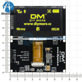
 A quick search on ebay for similar 2.42" OLED displays returns a different style, already mounted on a larger PCB:


This may fit on the Arduino protoshield, but it may look bulky.

Wise time with Arduino 20 Jul 19:41
oled