Posts with «xbee» label

Control a swarm of drones with this wearable tactile device

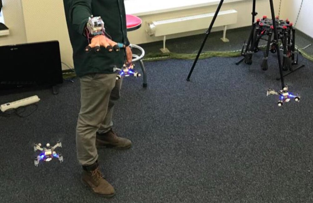
If you fly drones for fun—or perhaps even for work—you know that piloting them can sometimes be a difficult tasks. Imagine, however, trying to control four drones simultaneously. While also “challenging,” researchers at the Skolkovo Institute of Science and Technology in Russia have come up with a new approach for commanding such a swarm using only arm movements.

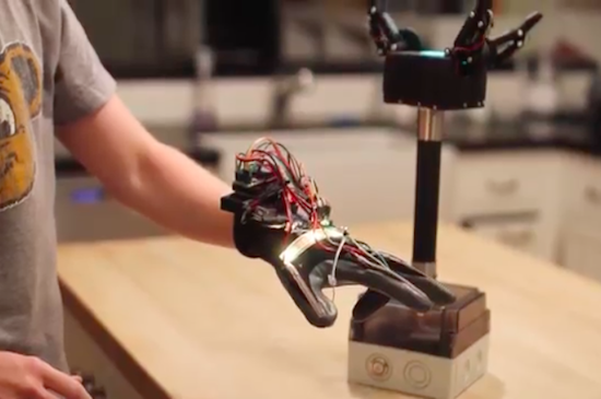
SwarmTouch takes the form of a wrist and finger-mounted device, with an array of eight cameras tracking its position. When the operator moves their arm, the drones react to the hand motion and the other flying robots in the group, as if there was a mechanical system linking each one together. 

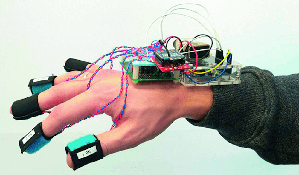
Feedback is provided by an Arduino Uno connected to the control station via an XBee radio, which tells the operator whether the swarm is expanding or contracting using vibration motors on a wearer’s fingertips. The setup is on display in the video below and its research paper can be found here.

We propose a novel interaction strategy for a human-swarm communication when a human operator guides a formation of quadrotors with impedance control and receives vibrotactile feedback. The presented approach takes into account the human hand velocity and changes the formation shape and dynamics accordingly using impedance interlinks simulated between quadrotors, which helps to achieve a life-like swarm behavior. Experimental results with Crazyflie 2.0 quadrotor platform validate the proposed control algorithm. The tactile patterns representing dynamics of the swarm (extension or contraction) are proposed. The user feels the state of the swarm at his fingertips and receives valuable information to improve the controllability of the complex life-like formation. The user study revealed the patterns with high recognition rates. Subjects stated that tactile sensation improves the ability to guide the drone formation and makes the human-swarm communication much more interactive. The proposed technology can potentially have a strong impact on the human- swarm interaction, providing a new level of intuitiveness and immersion into the swarm navigation.

Arduino Blog 01 Oct 17:03
arduino  drones  featured  uno  xbee  

SENSEation Shows The Importance of Good Physical Design

Sensor network projects often focus primarily on electronic design elements, such as architecture and wireless transmission methods for sensors and gateways. Equally important, however, are physical and practical design elements such as installation, usability, and maintainability. The SENSEation project by [Mario Frei] is a sensor network intended for use indoors in a variety of buildings, and it showcases the deep importance of physical design elements in order to create hardware that is easy to install, easy to maintain, and effective. The project logs have an excellent overview of past versions and an analysis of what worked well, and where they fell short.

One example is the power supply for the sensor nodes. Past designs used wall adapters to provide constant and reliable power, but there are practical considerations around doing so. Not only do power adapters mean each sensor requires some amount of cable management, but one never really knows what one will find when installing a node somewhere in a building; a power outlet may not be nearby, or it may not have any unoccupied sockets. [Mario] found that installations could take up to 45 minutes per node as a result of these issues. The solution was to move to battery power for the sensor nodes. With careful power management, a node can operate for almost a year before needing a recharge, and removing any cable management or power adapter meant that installation time dropped to an average of only seven minutes.

That’s just one example of the practical issues discovered in the deployment of a sensor network in a real-world situation, and the positive impact of some thoughtful design changes in response. The GitHub repository for SENSEation has all the details needed to reproduce the modular design, so check it out.

Why Have Only One Radio, When You Can Have Two?

There are a multitude of radio shields for the Arduino and similar platforms, but they so often only support one protocol, manufacturer, or frequency band. [Jan Gromeš] was vexed by this in a project he saw, so decided to create a shield capable of supporting multiple different types. And because more is so often better, he also gave it space for not one, but two different radio modules. He calls the resulting Swiss Army Knife of Arduino radio shields the Kite, and he’s shared everything needed for one on a hackaday.io page and a GitHub repository.

Supported so far are ESP8266 modules, HC-05 Bluetooth modules, RFM69 FSK/OOK modules, SX127x series LoRa modules including SX1272, SX1276 and SX1278, XBee modules (S2B), and he claims that more are in development. Since some of those operate in very similar frequency bands it would be interesting to note whether any adverse effects come from their use in close proximity. We suspect there won’t be because the protocols involved are designed to be resilient, but there is nothing like a real-world example to prove it.

This project is unique, so we’re struggling to find previous Hackaday features of analogous ones. We have however looked at an overview of choosing the right wireless tech.

Hack a Day 28 Jul 09:00

A community-made, Arduino-powered interactive town map

A group of students from Farmington, Connecticut partnered with artist Balam Soto and master teachers Earl Procko and Jim Corrigan to create a community-based sculpture project that allows people to explore the sights, sounds and history of their town through new media.

The installation runs on Arduino Uno and XBee, and is comprised of two panels which act as viewing screens for multiple visual projections. Visitors can interact with the display and manipulate the images using 24 buttons placed on the physical map. Plus, they are encouraged to record and add their own stories and memories of Farmington to the ever-growing multimedia library.

Permanently exhibited in Farmington’s public library, the Farmington Map Project was also the opportunity to introduce the students to physical computing, digital fabrication, woodworking, Arduino programming, and to the potential that Makerspaces have to offer for bringing ideas to life.

The project was created with the support of an Arts in Education Mini-Grant, funded by the Connecticut State Department of Education, the Department of Economic and Community Development, the Connecticut Office of the Arts, and the Connecticut Association of Schools, Farmington High School’s Fine and Applied Arts.

Interested? Check it out on Hackster.

Throwback: Machine pours a drink every time the U.S. wins a medal

What do you get when you combine the Olympics, alcohol, and Arduino? An awesome machine that automatically pours a shot whenever your country wins a medal. Although a throwback, we can’t see why this project can’t be replicated for Rio!

It all began four years ago when a bunch of Makers were given early access to the SmartThings platform. To coincide with the London 2012 Summer Games, the team developed a device that would celebrate a U.S. victory by dispensing one of three different drinks–Goldschläger for gold, Jose Cuervo for silver, and Jack Daniels for bronze–while waving the American flag, turning on a strobe light, and playing the national anthem.

An Arduino is connected to a SparkFun XBee shield and the ZigBee network links it to the SmartThings platform online. The Arduino controls the servos responsible for releasing the liquid into the glass, and the relays that switch the power strip on/off for the party effects. Of course, you can always just pour a drink manually by selecting the appropriate medal on the accompanying SmartThings Medal app.

With the 2016 Games now underway, check out the entire build below to help get you started on a machine of your own!


Arduino Blog 11 Aug 21:43

In Bed With an Arduino, Fighting Sleep Apnea

Sometimes the journey is as interesting as the destination, and that’s certainly the case with [Marc]’s pursuit of measuring his sleep apnea (PDF, talk slides. Video embedded below.). Sleep apnea involves periods of time when you don’t breathe or breathe shallowly for as long as a few minutes and affects 5-10% of middle-aged men (half that for women.) [Marc]’s efforts are still a work-in-progress but along the way he’s tried a multitude of things, all involving different technology and bugs to work out. It’s surprising how many ways there are to monitor breathing.

Debugging the Eeonyx conductive fabric approach

His attempts started out using a MobSenDat Kit, which includes an Arduino compatible board, and an accelerometer to see just what his sleeping positions were. That was followed by measuring blood O2 saturation using a cheap SPO2 sensor that didn’t work out, and one with Bluetooth that did work but gave results as a graph and not raw data.

Next came measuring breathing by detecting airflow from his nose using a Wind Sensor, but the tubes for getting the “wind” from his nose to the sensor were problematic, though the approach was workable. In parallel with the Wind Sensor he also tried the Zeo bedside sleep manager which involves wearing a headband that uses electrical signals from your brain to tell you what sleep state you’re in. He particularly liked this one as it gave access to the data and even offered some code.

And his last approach we know of was to monitor breathing by putting some form of band around his chest/belly to measure expansion and contraction. He tried a few bands and an Eeonyx conductive textile/yarn turned out to be the best. He did run into noise issues with the Xbee, as well as voltage regulator problems, and a diode that had to be bypassed.

But while [Marc]’s list of approaches to monitor sleep is long, he hasn’t exhausted all approaches. For example there’s monitoring a baby using lasers to detect whether or not the child is still breathing.

[Via Adafruit]


Filed under: Medical hacks
Hack a Day 14 Jul 00:00

Grab things with an Arduino robotic gripper

Sam Baumgarten and his friend have developed a pretty rad robotic gripper with the help of Arduino and 3D printing. The gripper itself consists of three large hobby servos joined to the fingers with a linkage. The underactuated fingers have a force sensor under each contact point, while the control glove is equipped with tiny vibrating motors at the fingertips. This, of course, provides haptic feedback to ensure that the user doesn’t crush anything–the greater the pressure, the stronger the motors vibrate.

The gripper is mounted to a handle with abrasive tape–the same kind found on staircases and skateboards. The tape is also used on each finger for optimal gripping. A box at the base of the pole houses all of the electronics, which include an Arduino Pro Mini for controlling the addressable LEDs on top, another Arduino for handling the communication and fingers, and a battery for power.

Aside from the vibration motors, the glove features flexible resistors on the back of the fingers, an LED strip for visualization, a breakout board for measuring the resistance from the flex sensors, a battery, an Arduino Uno for processing, and an XBee module for transmitting the signals to the Arduino in the gripper.

If you think this sounds awesome, wait until you see it in action. Baumgartnen has shared a demo of the project, along with a detailed breakdown of his build. Kudos to Hackaday for finding this incredible piece of work!

Xbee and Arduino sent to space by NASA

Last July 7 at Wallops Flight Facility, NASA launched Black Brant IX , a suborbital sounding rocket to test “wireless-in-space” with XBee and Arduino :

Onboard the rocket was an experiment testing Exo-Brake technology. XBee was used to collect sensor data including temperature, air pressure, and 3-axis acceleration parameters. NASA is considering Exo-brakes as a possible solution for returning cargo from the International Space Station (ISS), orbiting platforms or as possible landing mechanisms in low-density atmospheres. This was one of many tests used to analyze its effectiveness, but the first to incorporate an XBee connected sensor network. If you would like to read more about the Exo-brake, check out this article.

As part of a program to determine potential applications of wireless technologies in space, NASA chose XBee® ZigBee modules and Arduino Mega  explaining that:

Wireless sensor technology allows measuring important parameters such as aerodynamic pressure and temperature at the apex of the Exo-Brake during re-entry. It is very difficult to instrument a deployable parachute like the Exo-Brake, and wireless sensor modules provide the means for this type of measurement where it is difficult to run wires,” said Rick Alena, computer engineer at NASA Ames.

The NASA team constructed a gateway using an Arduino Mega, XBee, and Iridium module. The Arduino Mega was used to manage communications between the local XBee wireless network and the long-range Iridium satellite uplink. It was chosen as part of a NASA initiative to use commercial off-the-shelf components where possible, and to employ rapid prototyping tools to efficiently explore new ideas.

See the diagram below to get a detailed view into how the network was configured.


Arduino Blog 31 Jul 17:20
arduino mega  featured  mega  space  xbee  

Modding WiFiChron with GPS or Bluetooth

The latest revision of WiFiChron has an XBee socket (beside the ESP8266 8-pin socket), which allows the addition of a few individual features:
  1. GPS-based time synchronization, by using the GPSBee;
  2. displaying messages sent from a Bluetooth device, by using the BTBee/BLEBee;
  3. displaying data acquired from an XBee/ZigBee network of sensors (not implemented yet);


Things did not go smoothly, without some drama though. Naively (I always seem to forget that there is a difference between theory and practice), I designed the XBee/ESP to connect to the serial port, with the expectation that once the development (including testing with debug statements to the serial monitor) is done, I will just plug in the serial module (either XBee of ESP8266) and things will work properly. Well, I had to re-consider this approach once again. Luckily, I had two pins left available (D7 and D17), which I could use for software serial. I re-wired those to the XBee/ESP and used the hardware serial for console communication. Until the next board revision, anyone wanting to follow will need to re-route a couple of traces manually, as shown in the photos below (cuts are red-circled).


A few details on my implementation of the GPS time sync (so that one doesn't need to look at the code to figure it out):
  • user can set a timezone (stored in eeprom, default is -1); there is no (easy) way to determine if the timezone was set or not, since -1 (eeprom byte being 255) is a valid value;
  • estimate the timezone from the longitude, assuming that a every 15 degrees is an hour difference;
  • a difference between GPS estimated timezone and the user-set timezone of more than 2 hours would mean that the time is way off and the user did not set the timezone; in this case, blink the display; a difference of 2 hours or less would be acceptable (for many reasons, including summer-time, or variations from the "15-degrees-longitude-per-hour" approximation);
  • in any case, the minutes and seconds are set from the GPS data;
  • date and day are not set/synchronized at all (currently);
  • the GPS sync is scheduled to happen every 10 hours (and also after a reset);
  • a successful sync is indicated by an up arrow at the end of the scrolling date (e.g. March 29, 2015 ^).
I will publish the code as soon as I have a chance to polish it (and also test it with BTBee).

Wise time with Arduino 29 Mar 18:44
bluetooth  hdsp  xbee  

Water Tank Monitoring System Is Now Slug-Proof

[Peter] is doing his part toward protecting the environment and conserving water. He’s built a rainwater collection system complete with an underground storage tank. Since he wanted to monitor the water level in the tank, he made a level indicating system. Everything was going well until one day out of nowhere it stopped working, only returning 0’s as the level. [Peter] took a look and found that I slug had made its way into the electronics enclosure and slimed up the traces on the PCB, causing short circuits.To fix the problem [Peter] decided to redesigned the system. This time it would be built into an all-weather electrical box. The system uses a standard hobby ultrasonic range finder to measure the distance from the top of the tank to the level of the water. Two holes cut into the electrical box allow the sender/receiver components to peek outside of the enclosure. Any gaps were then filled with sealant. [Peter] also added a thermistor to measure the temperature inside the tank.The sensor values are read by an Arduino and sent wirelessly to [Peter]’s computer via a pair of XBee’s and a second Arduino with an ethernet shield. The data are sent in 3 minute intervals and automatically stored in a MySQL database for quick reference of level and temperature trends. Now [Peter] can monitor his rain water remotely and adjust his usage habits accordingly. Want to read more about water tanks? Check out this overflow monitor system.

Filed under: green hacks