Posts with «analog» label

Tutorial – the Arduino AREF Pin

Learn how to measure smaller voltages with greater accuracy using your Arduino.

In this tutorial we’ll look at how you can measure smaller voltages with greater accuracy using the analogue input pins on your Arduino Uno R1 to R3 (not R4!) or compatible board in conjunction with the AREF pin. However first we’ll do some revision to get you up to speed. Please read this post entirely before working with AREF the first time.

Revision

You may recall from previous Arduino tutorials that we used the analogRead() function to measure the voltage of an electrical current from sensors and so on using one of the analogue input pins. The value returned from analogRead() would be between zero an 1023, with zero representing zero volts and 1023 representing the operating voltage of the Arduino board in use.

And when we say the operating voltage – this is the voltage available to the Arduino after the power supply circuitry. For example, if you have a typical Arduino Uno board and run it from the USB socket – sure, there is 5V available to the board from the USB socket on your computer or hub – but the voltage is reduced slightly as the current winds around the circuit to the microcontroller – or the USB source just isn’t up to scratch.

This can easily be demonstrated by connecting an Arduino Uno to USB and putting a multimeter set to measure voltage across the 5V and GND pins. Some boards will return as low as 4.8 V, some higher but still below 5V. So if you’re gunning for accuracy, power your board from an external power supply via the DC socket or Vin pin – such as 9V DC. Then after that goes through the power regulator circuit you’ll have a nice 5V, for example:

This is important as the accuracy of any analogRead() values will be affected by not having a true 5 V. If you don’t have any option, you can use some maths in your sketch to compensate for the drop in voltage. For example, if your voltage is 4.8V – the analogRead() range of 0~1023 will relate to 0~4.8V and not 0~5V. This may sound trivial, however if you’re using a sensor that returns a value as a voltage (e.g. the TMP36 temperature sensor) – the calculated value will be wrong. So in the interests of accuracy, use an external power supply.

Why does analogRead() return a value between 0 and 1023?

This is due to the resolution of the ADC. The resolution (for this article) is the degree to which something can be represented numerically. The higher the resolution, the greater accuracy with which something can be represented. We measure resolution in the terms of the number of bits of resolution.

For example, a 1-bit resolution would only allow two (two to the power of one) values – zero and one. A 2-bit resolution would allow four (two to the power of two) values – zero, one, two and three. If we tried to measure  a five volt range with a two-bit resolution, and the measured voltage was four volts, our ADC would return a numerical value of 3 – as four volts falls between 3.75 and 5V. It is easier to imagine this with the following image:

 So with our example ADC with 2-bit resolution, it can only represent the voltage with four possible resulting values. If the input voltage falls between 0 and 1.25, the ADC returns numerical 0; if the voltage falls between 1.25 and 2.5, the ADC returns a numerical value of 1. And so on. With our Arduino’s ADC range of 0~1023 – we have 1024 possible values – or 2 to the power of 10. So our Arduinos have an ADC with a 10-bit resolution.

So what is AREF? 

To cut a long story short, when your Arduino takes an analogue reading, it compares the voltage measured at the analogue pin being used against what is known as the reference voltage. In normal analogRead use, the reference voltage is the operating voltage of the board. For the more popular Arduino boards such as the Uno, Mega, Duemilanove and Leonardo/Yún boards, the operating voltage of 5V. If you have an Arduino Due board, the operating voltage is 3.3V. If you have something else – check the Arduino product page or ask your board supplier.

So if you have a reference voltage of 5V, each unit returned by analogRead() is valued at 0.00488 V. (This is calculated by dividing 1024 into 5V). What if we want to measure voltages between 0 and 2, or 0 and 4.6? How would the ADC know what is 100% of our voltage range?

And therein lies the reason for the AREF pin. AREF means Analogue REFerence. It allows us to feed the Arduino a reference voltage from an external power supply. For example, if we want to measure voltages with a maximum range of 3.3V, we would feed a nice smooth 3.3V into the AREF pin – perhaps from a voltage regulator IC. Then the each step of the ADC would represent around 3.22 millivolts (divide 1024 into 3.3).

Note that the lowest reference voltage you can have is 1.1V. There are two forms of AREF – internal and external, so let’s check them out.

External AREF

An external AREF is where you supply an external reference voltage to the Arduino board. This can come from a regulated power supply, or if you need 3.3V you can get it from the Arduino’s 3.3V pin. If you are using an external power supply, be sure to connect the GND to the Arduino’s GND pin. Or if you’re using the Arduno’s 3.3V source – just run a jumper from the 3.3V pin to the AREF pin.

To activate the external AREF, use the following in void setup():

analogReference(EXTERNAL); // use AREF for reference voltage

This sets the reference voltage to whatever you have connected to the AREF pin – which of course will have a voltage between 1.1V and the board’s operation voltage.

Very important note – when using an external voltage reference, you must set the analogue reference to EXTERNAL before using analogRead(). This will prevent you from shorting the active internal reference voltage and the AREF pin, which can damage the microcontroller on the board.

If necessary for your application, you can revert back to the board’s operating voltage for AREF (that is – back to normal) with the following:

analogReference(DEFAULT);

Now to demonstrate external AREF at work. Using a 3.3V AREF, the following sketch measures the voltage from A0 and displays the percentage of total AREF and the calculated voltage:

#include <LiquidCrystal.h>
LiquidCrystal lcd(8,9,4,5,6,7);

int analoginput = 0; // our analog pin
int analogamount = 0; // stores incoming value
float percentage = 0; // used to store our percentage value
float voltage =0; // used to store voltage value

void setup()
{
  lcd.begin(16, 2);
  analogReference(EXTERNAL); // use AREF for reference voltage
}

void loop()
{
  lcd.clear();
  analogamount=analogRead(analoginput);
  percentage=(analogamount/1024.00)*100;
  voltage=analogamount*3.222; // in millivolts
  lcd.setCursor(0,0);
  lcd.print("% of AREF: ");
  lcd.print(percentage,2);
  lcd.setCursor(0,1);  
  lcd.print("A0 (mV): ");
  lcd.println(voltage,2);
  delay(250);
}

The results of the sketch above are shown in the following video:

Internal AREF

The microcontrollers on our Arduino boards can also generate an internal reference voltage of 1.1V and we can use this for AREF work. Simply use the line:

analogReference(INTERNAL);

For Arduino Mega boards, use:

analogReference(INTERNAL1V1);

in void setup() and you’re off. If you have an Arduino Mega there is also a 2.56V reference voltage available which is activated with:

analogReference(INTERNAL2V56);

Finally – before settling on the results from your AREF pin, always calibrate the readings against a known good multimeter.

Conclusion

The AREF function gives you more flexibility with measuring analogue signals. If you are interested in using specific ADC components, we have tutorials on the ADS1110 16-bit ADC and the NXP PCF 8591 8-bit A/D and D/A IC.

To keep up to date with new posts at tronixstuff.com, please subscribe to the mailing list in the box on the right, or follow us on X – @tronixstuff.

I hope you enjoyed making this or at least reading about it. If you find this sort of thing interesting, please consider ordering one or more of my books from amazon.

And as always, have fun and make something.

Clock Mixes Analog, Digital, Retrograde Displays

Unique clocks are a mainstay around here, and while plenty are “human readable” without any instruction, there are a few that take a bit of practice before someone can glean the current time from them. Word clocks are perhaps on the easier side of non-traditional displays but at the other end are binary clocks or even things like QR code clocks. To get the best of both worlds, though, multiple clock faces can be combined into one large display like this clock build from [imitche3].

The clock is actually three clocks in one. The first was inspired by a binary clock originally found in a kit, which has separate binary “digits” for hour, minute, and second and retains the MAX 7219 LED controller driving the display. A standard analog clock rests at the top, and a third clock called a retrograde clock sits at the bottom with three voltmeters that read out the time in steps. Everything is controlled by an Arduino Nano with the reliable DS3231 keeping track of time. The case can be laser-cut or 3D printed and [imitche3] has provided schematics for both options.

As far as clocks builds go, we always appreciate something which can be used to tell the time without needing any legends, codes, or specialized knowledge. Of course, if you want to take a more complex or difficult clock face some of the ones we’re partial to are this QR code clock which needs a piece of hardware to tell the time that probably already has its own clock on it.

Unique Clock is All Hands, No Dial, and Does the Worm

Back in the old days, we didn’t have fancy digital clocks. No, we had good analog clocks with a big hand and a little hand, and if you wanted to know the time you had to look at the clock and figure out which number each hand was pointing at, or kind of pointing at. It wasn’t easy, and we liked it that way.

So now, along comes an analog clock that’s nothing but the hands — no dial, no numbers, just hands. How is such a thing possible? The clue is in the clock’s name: AKUROBATTO, and in the video below, which shows the acrobatic movements of the clock’s hands as it does its thing. Serial improbable-clock maker [ekaggrat singh kalsi] clearly put a lot of thought into this mechanism, which consists of the hands and a separate base. The hands are joined together at one end and powered by small stepper motors. The base has two docking areas, where servo-driven claws can grasp the hand assembly, either at the center pivot or at the tip of either hand. With a little bit of shuffling around at transition points, the hands sweep out the hours and minutes in a surprisingly readable way.

For as cool as the design of AKUROBATTO is, the internals are really something else. There are custom-built slip rings to send power to the motors and the Arduinos controlling them, sensors to determine the position of each hand, and custom gearboxes for the steppers. And the locking mechanisms on the base are worth studying too — getting that right couldn’t have been easy.

All in all, an impressive build. Whether displaying the time on a phosphorescent screen or a field of sequins, it seems like [ekaggrat] has a thing for unique clocks.

Hack a Day 17 Feb 21:00

PsyLink An Open Source Neural Interface For Non-Invasive EMG

We don’t see many EMG (electromyography) projects, despite how cool the applications can be. This may be because of technical difficulties with seeing the tiny muscular electrical signals amongst the noise, it could be the difficulty of interpreting any signal you do find. Regardless, [hut] has been striving forwards with a stream of prototypes, culminating in the aptly named ‘Prototype 8’

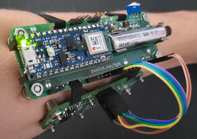
The current prototype uses a main power board hosting an Arduino Nano 33 BLE Sense, as well as a boost converter to pump up the AAA battery to provide 5 volts for the Arduino and a selection of connected EMG amplifier units. The EMG sensor is based around the INA128 instrumentation amplifier, in a pretty straightforward configuration. The EMG samples along with data from the IMU on the Nano 33 BLE Sense, are passed along to a connected PC via Bluetooth, running the PsyLink software stack. This is based on Python, using the BLE-GATT library for BT comms, PynPut handing the PC input devices (to emit keyboard and mouse events) and tensorflow for the machine learning side of things. The idea is to use machine learning from the EMG data to associate with a specific user interface event (such as a keypress) and with a little training, be able to play games on the PC with just hand/arm gestures. IMU data are used to augment this, but in this demo, that’s not totally clear.

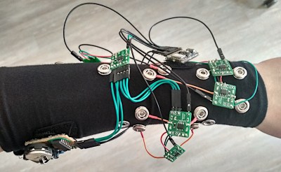
An earlier prototype of the PsyLink.

All hardware and software can be found on the project codeberg page, which did make us double-take as to why GnuRadio was being used, but thinking about it, it’s really good for signal processing and visualization. What a good idea!

Obviously there are many other use cases for such a EMG controlled input device, but who doesn’t want to play Mario Kart, you know, for science?

Checkout the demo video (embedded below) and you can see for yourself, just be aware that this is streaming from peertube, so the video might be a little choppy depending on your local peers. Finally, if Mastodon is your cup of tea, here’s the link for that. Earlier projects have attempted to dip into EMG before, like this Bioamp board from Upside Down Labs. Also we dug out an earlier tutorial on the subject by our own [Bil Herd.]

Detect Lightning Strikes with an Arduino

Lightning is a powerful and seemingly mysterious force of nature, capable of releasing huge amounts of energy over relatively short times and striking almost at random. Lightning obeys the laws of physics just like anything else, though, and with a little bit of technology some of its mysteries can be unraveled. For one, it only takes a small radio receiver to detect lightning strikes, and [mircemk] shows us exactly how to do that.

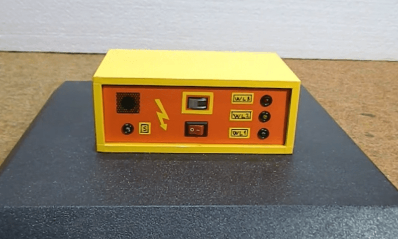
When lightning flashes, it also lights up an incredibly wide spectrum of radio spectrum as well. This build uses an AM radio built into a small integrated circuit to detect some of those radio waves. An Arduino Nano receives the signal from the TA7642 IC and lights up a series of LEDs as it detects strikes in closer and closer proximity to the detector. A white LED flashes when a strike is detected, and some analog circuitry supports an analog galvanometer which moves during lightning strikes as well.

While this project isn’t the first lightning detector we’ve ever seen, it does have significantly more sensitivity than most other homemade offerings. Something like this would be a helpful tool to have for lifeguards at a pool or for a work crew that is often outside, but we also think it’s pretty cool just to have around for its own sake, and three of them networked together would make triangulation of strikes possible too.

Supersized Weather Station Uses Antique Analog Meters

For most of us, getting weather information is as trivial as unlocking a smartphone or turning on a computer and pointing an app or browser at one’s weather site of choice. This is all well and good, but it lacks a certain panache that old weather stations had with their analog dials and stained wood cases. The weather station that [BuildComics] created marries both this antique aesthetic with modern weather data availability, and then dials it up a notch for this enormous analog weather station build.

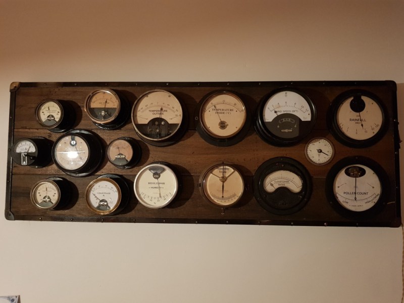
The weather station uses 16 discrete dials, each modified with a different label for the specific type of data displayed. Some of them needed new glass, and others also needed coils to be modified to be driven with a lower current than they were designed as well, since each would be driven by one of two Arduinos in this project. Each are tied to a microcontroller output via a potentiometer which controls the needle’s position for the wildly different designs of meter. The microcontrollers themselves get weather information via the internet, which allows for about as up-to-date information about the weather as one could gather first-hand.

The amount of customization of these old meters is impressive, and what’s even more impressive is the project’s final weight. [BuildComics] reports that it took two people just to lift it onto the wall mount, which is not surprising given the amount of iron in some of these old analog meters. And, although not as common in the real world anymore, these old antique meters have plenty of repurposed uses beyond weather stations as well.

Hack an Old DC Motor to Provide Rotary Input

Watch a Redditor share how he hacked a DC motor and hooked it up to an Arduino to use as an encoder.

Read more on MAKE

The post Hack an Old DC Motor to Provide Rotary Input appeared first on Make: DIY Projects, How-Tos, Electronics, Crafts and Ideas for Makers.

Printing Text with a Chart Recorder

Chart recorders are vintage devices that were used to plot analog values on paper. They’re similar to old seismometers which plot seismic waves from earthquakes. The device has a heated pen which moves across a piece of thermally sensitive paper. This paper is fed through the machine at a specified rate, which gives two dimensions of plotting.

[Marv] ended up getting a couple of discontinued chart recorders and figured out the interface. Five parallel signals control the feed rate of the paper, and an analog voltage controls the pen location. The next logical step was to hook up an Arduino to control the plotter.

However, once the device could plot analog values, [Marv] quickly looked for a new challenge. He wanted to write characters and bitmaps using the device, but this would require non-continuous lines. By adding a solenoid to lift the pen, he built a chart recorder printer.

After the break, check out a video of the chart recorder doing something it was never intended to do. If you happen to have one of these chart recorders, [Marv] included all of the code in his writeup to help you build your own.


Filed under: classic hacks

Arduino Tutorials – Chapter 22 – the AREF pin

Learn how to measure smaller voltages with greater accuracy using your Arduino.

This is chapter twenty-two of our huge Arduino tutorial seriesUpdated 12/12/2013

In this chapter we’ll look at how you can measure smaller voltages with greater accuracy using the analogue input pins on your Arduino or compatible board in conjunction with the AREF pin. However first we’ll do some revision to get you up to speed. Please read this post entirely before working with AREF the first time.

Revision

You may recall from the first few chapters in our tutorial series that we used the analogRead() function to measure the voltage of an electrical current from sensors and so on using one of the analogue input pins. The value returned from analogRead() would be between zero an 1023, with zero representing zero volts and 1023 representing the operating voltage of the Arduino board in use.

And when we say the operating voltage – this is the voltage available to the Arduino after the power supply circuitry. For example, if you have a typical Arduino Uno board and run it from the USB socket – sure, there is 5V available to the board from the USB socket on your computer or hub – but the voltage is reduced slightly as the current winds around the circuit to the microcontroller – or the USB source just isn’t up to scratch.

This can easily be demonstrated by connecting an Arduino Uno to USB and putting a multimeter set to measure voltage across the 5V and GND pins. Some boards will return as low as 4.8 V, some higher but still below 5V. So if you’re gunning for accuracy, power your board from an external power supply via the DC socket or Vin pin – such as 9V DC. Then after that goes through the power regulator circuit you’ll have a nice 5V, for example:

This is important as the accuracy of any analogRead() values will be affected by not having a true 5 V. If you don’t have any option, you can use some maths in your sketch to compensate for the drop in voltage. For example, if your voltage is 4.8V – the analogRead() range of 0~1023 will relate to 0~4.8V and not 0~5V. This may sound trivial, however if you’re using a sensor that returns a value as a voltage (e.g. the TMP36 temperature sensor) – the calculated value will be wrong. So in the interests of accuracy, use an external power supply.

Why does analogRead() return a value between 0 and 1023?

This is due to the resolution of the ADC. The resolution (for this article) is the degree to which something can be represented numerically. The higher the resolution, the greater accuracy with which something can be represented. We measure resolution in the terms of the number of bits of resolution.

For example, a 1-bit resolution would only allow two (two to the power of one) values – zero and one. A 2-bit resolution would allow four (two to the power of two) values – zero, one, two and three. If we tried to measure  a five volt range with a two-bit resolution, and the measured voltage was four volts, our ADC would return a numerical value of 3 – as four volts falls between 3.75 and 5V. It is easier to imagine this with the following image:

 So with our example ADC with 2-bit resolution, it can only represent the voltage with four possible resulting values. If the input voltage falls between 0 and 1.25, the ADC returns numerical 0; if the voltage falls between 1.25 and 2.5, the ADC returns a numerical value of 1. And so on. With our Arduino’s ADC range of 0~1023 – we have 1024 possible values – or 2 to the power of 10. So our Arduinos have an ADC with a 10-bit resolution.

So what is AREF? 

To cut a long story short, when your Arduino takes an analogue reading, it compares the voltage measured at the analogue pin being used against what is known as the reference voltage. In normal analogRead use, the reference voltage is the operating voltage of the board. For the more popular Arduino boards such as the Uno, Mega, Duemilanove and Leonardo/Yún boards, the operating voltage of 5V. If you have an Arduino Due board, the operating voltage is 3.3V. If you have something else – check the Arduino product page or ask your board supplier.

So if you have a reference voltage of 5V, each unit returned by analogRead() is valued at 0.00488 V. (This is calculated by dividing 1024 into 5V). What if we want to measure voltages between 0 and 2, or 0 and 4.6? How would the ADC know what is 100% of our voltage range?

And therein lies the reason for the AREF pin. AREF means Analogue REFerence. It allows us to feed the Arduino a reference voltage from an external power supply. For example, if we want to measure voltages with a maximum range of 3.3V, we would feed a nice smooth 3.3V into the AREF pin – perhaps from a voltage regulator IC. Then the each step of the ADC would represent around 3.22 millivolts (divide 1024 into 3.3).

Note that the lowest reference voltage you can have is 1.1V. There are two forms of AREF – internal and external, so let’s check them out.

External AREF

An external AREF is where you supply an external reference voltage to the Arduino board. This can come from a regulated power supply, or if you need 3.3V you can get it from the Arduino’s 3.3V pin. If you are using an external power supply, be sure to connect the GND to the Arduino’s GND pin. Or if you’re using the Arduno’s 3.3V source – just run a jumper from the 3.3V pin to the AREF pin.

To activate the external AREF, use the following in void setup():

analogReference(EXTERNAL); // use AREF for reference voltage

This sets the reference voltage to whatever you have connected to the AREF pin – which of course will have a voltage between 1.1V and the board’s operation voltage.

Very important note – when using an external voltage reference, you must set the analogue reference to EXTERNAL before using analogRead(). This will prevent you from shorting the active internal reference voltage and the AREF pin, which can damage the microcontroller on the board.

If necessary for your application, you can revert back to the board’s operating voltage for AREF (that is – back to normal) with the following:

analogReference(DEFAULT);

Now to demonstrate external AREF at work. Using a 3.3V AREF, the following sketch measures the voltage from A0 and displays the percentage of total AREF and the calculated voltage:

#include <LiquidCrystal.h>
LiquidCrystal lcd(8,9,4,5,6,7);

int analoginput = 0; // our analog pin
int analogamount = 0; // stores incoming value
float percentage = 0; // used to store our percentage value
float voltage =0; // used to store voltage value

void setup()
{
  lcd.begin(16, 2);
  analogReference(EXTERNAL); // use AREF for reference voltage
}

void loop()
{
  lcd.clear();
  analogamount=analogRead(analoginput);
  percentage=(analogamount/1024.00)*100;
  voltage=analogamount*3.222; // in millivolts
  lcd.setCursor(0,0);
  lcd.print("% of AREF: ");
  lcd.print(percentage,2);
  lcd.setCursor(0,1);  
  lcd.print("A0 (mV): ");
  lcd.println(voltage,2);
  delay(250);
}

The results of the sketch above are shown in the following video:

Internal AREF

The microcontrollers on our Arduino boards can also generate an internal reference voltage of 1.1V and we can use this for AREF work. Simply use the line:

analogReference(INTERNAL);

For Arduino Mega boards, use:

analogReference(INTERNAL1V1);

in void setup() and you’re off. If you have an Arduino Mega there is also a 2.56V reference voltage available which is activated with:

analogReference(INTERNAL2V56);

Finally – before settling on the results from your AREF pin, always calibrate the readings against a known good multimeter.

Conclusion

The AREF function gives you more flexibility with measuring analogue signals. If you are interested in using specific ADC components, we have tutorials on the ADS1110 16-bit ADC and the NXP PCF 8591 8-bit A/D and D/A IC.

Stay tuned for upcoming Arduino tutorials by subscribing to the blog, RSS feed (top-right), twitter or joining our Google Group. And if you enjoyed the tutorial, or want to introduce someone else to the interesting world of Arduino – check out my book (now in a third printing!) “Arduino Workshop” from No Starch Press.


The post Arduino Tutorials – Chapter 22 – the AREF pin appeared first on tronixstuff.