Posts with «analogread» label

Tutorial – the Arduino AREF Pin

Learn how to measure smaller voltages with greater accuracy using your Arduino.

In this tutorial we’ll look at how you can measure smaller voltages with greater accuracy using the analogue input pins on your Arduino Uno R1 to R3 (not R4!) or compatible board in conjunction with the AREF pin. However first we’ll do some revision to get you up to speed. Please read this post entirely before working with AREF the first time.

Revision

You may recall from previous Arduino tutorials that we used the analogRead() function to measure the voltage of an electrical current from sensors and so on using one of the analogue input pins. The value returned from analogRead() would be between zero an 1023, with zero representing zero volts and 1023 representing the operating voltage of the Arduino board in use.

And when we say the operating voltage – this is the voltage available to the Arduino after the power supply circuitry. For example, if you have a typical Arduino Uno board and run it from the USB socket – sure, there is 5V available to the board from the USB socket on your computer or hub – but the voltage is reduced slightly as the current winds around the circuit to the microcontroller – or the USB source just isn’t up to scratch.

This can easily be demonstrated by connecting an Arduino Uno to USB and putting a multimeter set to measure voltage across the 5V and GND pins. Some boards will return as low as 4.8 V, some higher but still below 5V. So if you’re gunning for accuracy, power your board from an external power supply via the DC socket or Vin pin – such as 9V DC. Then after that goes through the power regulator circuit you’ll have a nice 5V, for example:

This is important as the accuracy of any analogRead() values will be affected by not having a true 5 V. If you don’t have any option, you can use some maths in your sketch to compensate for the drop in voltage. For example, if your voltage is 4.8V – the analogRead() range of 0~1023 will relate to 0~4.8V and not 0~5V. This may sound trivial, however if you’re using a sensor that returns a value as a voltage (e.g. the TMP36 temperature sensor) – the calculated value will be wrong. So in the interests of accuracy, use an external power supply.

Why does analogRead() return a value between 0 and 1023?

This is due to the resolution of the ADC. The resolution (for this article) is the degree to which something can be represented numerically. The higher the resolution, the greater accuracy with which something can be represented. We measure resolution in the terms of the number of bits of resolution.

For example, a 1-bit resolution would only allow two (two to the power of one) values – zero and one. A 2-bit resolution would allow four (two to the power of two) values – zero, one, two and three. If we tried to measure  a five volt range with a two-bit resolution, and the measured voltage was four volts, our ADC would return a numerical value of 3 – as four volts falls between 3.75 and 5V. It is easier to imagine this with the following image:

 So with our example ADC with 2-bit resolution, it can only represent the voltage with four possible resulting values. If the input voltage falls between 0 and 1.25, the ADC returns numerical 0; if the voltage falls between 1.25 and 2.5, the ADC returns a numerical value of 1. And so on. With our Arduino’s ADC range of 0~1023 – we have 1024 possible values – or 2 to the power of 10. So our Arduinos have an ADC with a 10-bit resolution.

So what is AREF? 

To cut a long story short, when your Arduino takes an analogue reading, it compares the voltage measured at the analogue pin being used against what is known as the reference voltage. In normal analogRead use, the reference voltage is the operating voltage of the board. For the more popular Arduino boards such as the Uno, Mega, Duemilanove and Leonardo/Yún boards, the operating voltage of 5V. If you have an Arduino Due board, the operating voltage is 3.3V. If you have something else – check the Arduino product page or ask your board supplier.

So if you have a reference voltage of 5V, each unit returned by analogRead() is valued at 0.00488 V. (This is calculated by dividing 1024 into 5V). What if we want to measure voltages between 0 and 2, or 0 and 4.6? How would the ADC know what is 100% of our voltage range?

And therein lies the reason for the AREF pin. AREF means Analogue REFerence. It allows us to feed the Arduino a reference voltage from an external power supply. For example, if we want to measure voltages with a maximum range of 3.3V, we would feed a nice smooth 3.3V into the AREF pin – perhaps from a voltage regulator IC. Then the each step of the ADC would represent around 3.22 millivolts (divide 1024 into 3.3).

Note that the lowest reference voltage you can have is 1.1V. There are two forms of AREF – internal and external, so let’s check them out.

External AREF

An external AREF is where you supply an external reference voltage to the Arduino board. This can come from a regulated power supply, or if you need 3.3V you can get it from the Arduino’s 3.3V pin. If you are using an external power supply, be sure to connect the GND to the Arduino’s GND pin. Or if you’re using the Arduno’s 3.3V source – just run a jumper from the 3.3V pin to the AREF pin.

To activate the external AREF, use the following in void setup():

analogReference(EXTERNAL); // use AREF for reference voltage

This sets the reference voltage to whatever you have connected to the AREF pin – which of course will have a voltage between 1.1V and the board’s operation voltage.

Very important note – when using an external voltage reference, you must set the analogue reference to EXTERNAL before using analogRead(). This will prevent you from shorting the active internal reference voltage and the AREF pin, which can damage the microcontroller on the board.

If necessary for your application, you can revert back to the board’s operating voltage for AREF (that is – back to normal) with the following:

analogReference(DEFAULT);

Now to demonstrate external AREF at work. Using a 3.3V AREF, the following sketch measures the voltage from A0 and displays the percentage of total AREF and the calculated voltage:

#include <LiquidCrystal.h>
LiquidCrystal lcd(8,9,4,5,6,7);

int analoginput = 0; // our analog pin
int analogamount = 0; // stores incoming value
float percentage = 0; // used to store our percentage value
float voltage =0; // used to store voltage value

void setup()
{
  lcd.begin(16, 2);
  analogReference(EXTERNAL); // use AREF for reference voltage
}

void loop()
{
  lcd.clear();
  analogamount=analogRead(analoginput);
  percentage=(analogamount/1024.00)*100;
  voltage=analogamount*3.222; // in millivolts
  lcd.setCursor(0,0);
  lcd.print("% of AREF: ");
  lcd.print(percentage,2);
  lcd.setCursor(0,1);  
  lcd.print("A0 (mV): ");
  lcd.println(voltage,2);
  delay(250);
}

The results of the sketch above are shown in the following video:

Internal AREF

The microcontrollers on our Arduino boards can also generate an internal reference voltage of 1.1V and we can use this for AREF work. Simply use the line:

analogReference(INTERNAL);

For Arduino Mega boards, use:

analogReference(INTERNAL1V1);

in void setup() and you’re off. If you have an Arduino Mega there is also a 2.56V reference voltage available which is activated with:

analogReference(INTERNAL2V56);

Finally – before settling on the results from your AREF pin, always calibrate the readings against a known good multimeter.

Conclusion

The AREF function gives you more flexibility with measuring analogue signals. If you are interested in using specific ADC components, we have tutorials on the ADS1110 16-bit ADC and the NXP PCF 8591 8-bit A/D and D/A IC.

To keep up to date with new posts at tronixstuff.com, please subscribe to the mailing list in the box on the right, or follow us on X – @tronixstuff.

I hope you enjoyed making this or at least reading about it. If you find this sort of thing interesting, please consider ordering one or more of my books from amazon.

And as always, have fun and make something.

Get Arduino Data over the internet using jQuery and AJAX


Description


Have you ever wanted to transmit Arduino data over the internet?

In this tutorial, we will design a web page that will retrieve Analog readings from the Arduino's Analog Pins and display them on a bar chart within the web page.

The web page will use jQuery and AJAX to request the data from the Arduino Web Server, allowing us to update the bar chart dynamically, without having to refresh the entire web page. The Arduino Web Server will send the Analog readings to the web page in JSON format where it will be processed and displayed accordingly.

In this tutorial, I will not have anything connected to the Arduino's Analog pins, which means the data retrieved will be that of randomly floating analog pins. Feel free to connect a potentiometer, temperature sensor or any other analog sensor to these pins if you want to create a more "useful" project.

The main aim here was to show you how to transmit the data in JSON format, and to update only a portion of the web page using asynchronous communication (using AJAX), to improve the performance of data retrieval and visualisation.


Parts Required:


Please note: The WIZnet ioShield-A ver1.1 actually comes with the WIZ550io board. So if you buy the ioShield-A, you will receive both boards. I have provided the link to the WIZ550io shield because you can buy that shield on its own. Regardless, you will need to use both boards for this tutorial.


Arduino Libraries and IDE


To program the Arduino you will need to download the Arduino IDE, and install the WIZnet Ethernet Library. The Arduino IDE version used in this tutorial was version 1.6.4.
You may want to read the WIZnet wiki information for each WIZnet shield before use.


ARDUINO CODE:


Full description of the Arduino code is included in the YouTube video above. Once you have set up your Arduino Web Server, you should be able to ping it. Look at this website, if you don't know how to use the windows ping feature.


Getting the Arduino Board onto the internet:


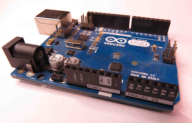
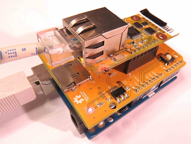
There isn't anything really to hook up for this project. You just have to align the pins for each board and stack them. You can power the Arduino via the USB cable. This will also be useful for debugging and printing to the Serial monitor. An ethernet cable needs to connect the WIZ550io board's ethernet port to your internet/network router

  • The WIZ550io board goes on the top

  • The ioShield-A is in the middle

  • The Arduino UNO is on the bottom

  • This is what it looks like when they are stacked together

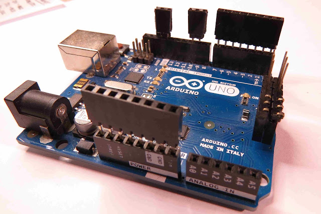
  • If you want to gain easy access to the Analog or digital pins without de-soldering the ioShield-A, you can introduce some female headers like this:

  • Please note that the ioShield-A utilises a number of pins on the Arduino UNO - including: D2, D4, D7, D10, GND, and IOREF, RESET, 5V, GND, GND and ICSP pins
  • All Analog pins are available for use


Set the Arduino Web Server on your local network


You can test this project on your local network. You just have to choose an available IP address and PORT within your router's IP range. If you don't know your local IP address range - you can have a look at this site to give you a helping hand.


Set the Arduino Web Server to be accessed from anywhere in the world


If you want to access your Arduino from anywhere in the world, you need to set up Port Forwarding on your internet network router. The following useful guides will hopefully get you on the right track, if you have never set up Port forwarding.


In my case, I programmed the Arduino UNO Web Server to take the following ip address on my internal network: 10.1.1.99

I programmed the Arduino Web Server to listen for Web Browsers on port 8081.
So if I wanted to connect to the Arduino Web Server through my home network, I just had to type in this web address into my web browser: http://10.1.1.99:8081

If you plan to connect to the Arduino using port 80 (which is the default port for web browsers), you can just type the IP address without specifying the port (eg. http://10.1.1.99/ )

The web browser should display the Arduino data in JSON format (the YouTube video above will show you what that looks like).

Once I knew I could connect to the Arduino in my internal network, I then set up port forwarding on my router so that I could type in my external IP address and special port to tunnel my way into my Arduino Web Server on my internal network. This is what I had to do on my router, but you may need to do something different.

  1. My first step was to find out my public/external IP address by typing "what is my IP address" into google. If you want to know your external IP address click here.
  2. I then typed my router's ip address into a web browser, and logged into my router.
  3. I went to the advanced settings tab
  4. Selected "Port Forwarding" from the side menu
  5. Filled out all of the details on the first line of the Ports list
    • Enable box = ticked
    • Description = Arduino
    • WAN interface = pppoe_atm0/ppp0
    • Inbound port = 8082
    • Type = TCP
    • Private IP address = 10.1.1.99
    • Private port = 8081
  6. Saved the settings

Now that I had port forwarding enabled, I could type the ip address (that I obtained in step 1) into my browser and specified port 8082 (instead of 8081) - eg. http://190.11.70.253:8082/

And now I can access my Arduino Web server from anywhere in the world. I can even access it from my smart phone. Once again, this will only return the Analog data in JSON format.


The Web Page GUI


The Arduino is now on the internet, so there are two options. You can either


Instructions on how to use these web pages, are listed below the HTML code.


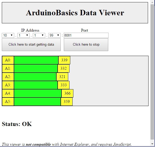
To retrieve data from your Arduino Web Server, please make sure that it is connected and visible from outside of you local network. You will need to have port forwarding enabled. Information on port forwarding is described above.
  1. Find what your external IP address is.
  2. Enter this address using the IP address drop-down boxes within the "ArduinoBasics Webserver Data viewer" web page
  3. Enter the port forwarding port number (eg. 8082) into the box labelled "Port"
  4. Then click on the "Click here to start getting data" button - you should start to see the bar charts moving and status should be OK
  5. If the bar charts do not move, and the status message says "Failed to get DATA!!" - then the web page was unable to connect to the Arduino for some reason.


Troubleshooting

  • You may want to type in the web address into your web browser, to make sure that data is being retrieved.
  • You can also open the Serial monitor in the Arduino IDE to make sure that an IP address is being displayed
  • Ensure that you have enabled the port forwarding option on your router
  • Have a look at Developer Tools within Google Chrome to help diagnose web page related issues.
  • The web page will not work properly if you use Internet Explorer or if you have javascript disabled within your browser.


Concluding comments


This tutorial showed you how to connect to your Arduino UNO over the internet, and retrieve data in JSON format using jQuery and AJAX. The web page can be modified to suit your own needs, plus it would be more useful if the Arduino was actually monitoring something, rather than logging data from floating pins. It would also be useful if the Arduino could be controlled to blink an LED, or to turn a motor... but I will leave that project for another day. Thank you.

If you like this page, please do me a favour and show your appreciation :

 
Visit my ArduinoBasics Google + page.
Follow me on Twitter by looking for ScottC @ArduinoBasics.
I can also be found on Pinterest and Instagram.
Have a look at my videos on my YouTube channel.
             
This project would not have been possible without WIZnet's collaborative effort.
Please visit their site for more cool Ethernet products.


However, if you do not have a google profile...
Feel free to share this page with your friends in any way you see fit.

Get Arduino Data over the internet using jQuery and AJAX

Description

Have you ever wanted to transmit Arduino data over the internet?

In this tutorial, we will design a web page that will retrieve Analog readings from the Arduino's Analog Pins and display them on a bar chart within the web page.

The web page will use jQuery and AJAX to request the data from the Arduino Web Server, allowing us to update the bar chart dynamically, without having to refresh the entire web page. The Arduino Web Server will send the Analog readings to the web page in JSON format where it will be processed and displayed accordingly.

In this tutorial, I will not have anything connected to the Arduino's Analog pins, which means the data retrieved will be that of randomly floating analog pins. Feel free to connect a potentiometer, temperature sensor or any other analog sensor to these pins if you want to create a more "useful" project.

The main aim here was to show you how to transmit the data in JSON format, and to update only a portion of the web page using asynchronous communication (using AJAX), to improve the performance of data retrieval and visualisation.


Arduino Libraries and IDE

To program the Arduino you will need to download the Arduino IDE, and install the WIZnet Ethernet Library. The Arduino IDE version used in this tutorial was version 1.6.4.
You may want to read the WIZnet wiki information for each WIZnet shield before use.


ARDUINO CODE:

Full description of the Arduino code is included in the YouTube video above. Once you have set up your Arduino Web Server, you should be able to ping it. Look at this website, if you don't know how to use the windows ping feature.


Getting the Arduino Board onto the internet:

There isn't anything really to hook up for this project. You just have to align the pins for each board and stack them. You can power the Arduino via the USB cable. This will also be useful for debugging and printing to the Serial monitor. An ethernet cable needs to connect the WIZ550io board's ethernet port to your internet/network router

  • The WIZ550io board goes on the top

  • The ioShield-A is in the middle

  • The Arduino UNO is on the bottom

  • This is what it looks like when they are stacked together

  • If you want to gain easy access to the Analog or digital pins without de-soldering the ioShield-A, you can introduce some female headers like this:

  • Please note that the ioShield-A utilises a number of pins on the Arduino UNO - including: D2, D4, D7, D10, GND, and IOREF, RESET, 5V, GND, GND and ICSP pins
  • All Analog pins are available for use


Set the Arduino Web Server on your local network

You can test this project on your local network. You just have to choose an available IP address and PORT within your router's IP range. If you don't know your local IP address range - you can have a look at this site to give you a helping hand.


Set the Arduino Web Server to be accessed from anywhere in the world

If you want to access your Arduino from anywhere in the world, you need to set up Port Forwarding on your internet network router. The following useful guides will hopefully get you on the right track, if you have never set up Port forwarding.


In my case, I programmed the Arduino UNO Web Server to take the following ip address on my internal network: 10.1.1.99

I programmed the Arduino Web Server to listen for Web Browsers on port 8081.
So if I wanted to connect to the Arduino Web Server through my home network, I just had to type in this web address into my web browser: http://10.1.1.99:8081

If you plan to connect to the Arduino using port 80 (which is the default port for web browsers), you can just type the IP address without specifying the port (eg. http://10.1.1.99/ )

The web browser should display the Arduino data in JSON format (the YouTube video above will show you what that looks like).

Once I knew I could connect to the Arduino in my internal network, I then set up port forwarding on my router so that I could type in my external IP address and special port to tunnel my way into my Arduino Web Server on my internal network. This is what I had to do on my router, but you may need to do something different.

  1. My first step was to find out my public/external IP address by typing "what is my IP address" into google. If you want to know your external IP address click here.
  2. I then typed my router's ip address into a web browser, and logged into my router.
  3. I went to the advanced settings tab
  4. Selected "Port Forwarding" from the side menu
  5. Filled out all of the details on the first line of the Ports list
    • Enable box = ticked
    • Description = Arduino
    • WAN interface = pppoe_atm0/ppp0
    • Inbound port = 8082
    • Type = TCP
    • Private IP address = 10.1.1.99
    • Private port = 8081
  6. Saved the settings

Now that I had port forwarding enabled, I could type the ip address (that I obtained in step 1) into my browser and specified port 8082 (instead of 8081) - eg. http://190.11.70.253:8082/

And now I can access my Arduino Web server from anywhere in the world. I can even access it from my smart phone. Once again, this will only return the Analog data in JSON format.


The Web Page GUI

The Arduino is now on the internet, so there are two options. You can either

Instructions on how to use these web pages, are listed below the HTML code.


To retrieve data from your Arduino Web Server, please make sure that it is connected and visible from outside of you local network. You will need to have port forwarding enabled. Information on port forwarding is described above.

  1. Find what your external IP address is.
  2. Enter this address using the IP address drop-down boxes within the "ArduinoBasics Webserver Data viewer" web page
  3. Enter the port forwarding port number (eg. 8082) into the box labelled "Port"
  4. Then click on the "Click here to start getting data" button - you should start to see the bar charts moving and status should be OK
  5. If the bar charts do not move, and the status message says "Failed to get DATA!!" - then the web page was unable to connect to the Arduino for some reason.


Troubleshooting

  • You may want to type in the web address into your web browser, to make sure that data is being retrieved.
  • You can also open the Serial monitor in the Arduino IDE to make sure that an IP address is being displayed
  • Ensure that you have enabled the port forwarding option on your router
  • Have a look at Developer Tools within Google Chrome to help diagnose web page related issues.
  • The web page will not work properly if you use Internet Explorer or if you have javascript disabled within your browser.

Concluding comments

This tutorial showed you how to connect to your Arduino UNO over the internet, and retrieve data in JSON format using jQuery and AJAX. The web page can be modified to suit your own needs, plus it would be more useful if the Arduino was actually monitoring something, rather than logging data from floating pins. It would also be useful if the Arduino could be controlled to blink an LED, or to turn a motor... but I will leave that project for another day. I hope you enjoyed this tutorial - if it helped you in any way, please consider donating a small "tip" into my money jar. Thank you.


If you like this page, please do me a favour and show your appreciation :

 
Visit my ArduinoBasics Google + page.
Follow me on Twitter by looking for ScottC @ArduinoBasics.
I can also be found on Pinterest and Instagram.
Have a look at my videos on my YouTube channel.


This project would not have been possible without WIZnet's collaborative effort.
Please visit their site for more cool Ethernet products.


However, if you do not have a google profile...
Feel free to share this page with your friends in any way you see fit.

Arduino Tutorials – Chapter 22 – the AREF pin

Learn how to measure smaller voltages with greater accuracy using your Arduino.

This is chapter twenty-two of our huge Arduino tutorial seriesUpdated 12/12/2013

In this chapter we’ll look at how you can measure smaller voltages with greater accuracy using the analogue input pins on your Arduino or compatible board in conjunction with the AREF pin. However first we’ll do some revision to get you up to speed. Please read this post entirely before working with AREF the first time.

Revision

You may recall from the first few chapters in our tutorial series that we used the analogRead() function to measure the voltage of an electrical current from sensors and so on using one of the analogue input pins. The value returned from analogRead() would be between zero an 1023, with zero representing zero volts and 1023 representing the operating voltage of the Arduino board in use.

And when we say the operating voltage – this is the voltage available to the Arduino after the power supply circuitry. For example, if you have a typical Arduino Uno board and run it from the USB socket – sure, there is 5V available to the board from the USB socket on your computer or hub – but the voltage is reduced slightly as the current winds around the circuit to the microcontroller – or the USB source just isn’t up to scratch.

This can easily be demonstrated by connecting an Arduino Uno to USB and putting a multimeter set to measure voltage across the 5V and GND pins. Some boards will return as low as 4.8 V, some higher but still below 5V. So if you’re gunning for accuracy, power your board from an external power supply via the DC socket or Vin pin – such as 9V DC. Then after that goes through the power regulator circuit you’ll have a nice 5V, for example:

This is important as the accuracy of any analogRead() values will be affected by not having a true 5 V. If you don’t have any option, you can use some maths in your sketch to compensate for the drop in voltage. For example, if your voltage is 4.8V – the analogRead() range of 0~1023 will relate to 0~4.8V and not 0~5V. This may sound trivial, however if you’re using a sensor that returns a value as a voltage (e.g. the TMP36 temperature sensor) – the calculated value will be wrong. So in the interests of accuracy, use an external power supply.

Why does analogRead() return a value between 0 and 1023?

This is due to the resolution of the ADC. The resolution (for this article) is the degree to which something can be represented numerically. The higher the resolution, the greater accuracy with which something can be represented. We measure resolution in the terms of the number of bits of resolution.

For example, a 1-bit resolution would only allow two (two to the power of one) values – zero and one. A 2-bit resolution would allow four (two to the power of two) values – zero, one, two and three. If we tried to measure  a five volt range with a two-bit resolution, and the measured voltage was four volts, our ADC would return a numerical value of 3 – as four volts falls between 3.75 and 5V. It is easier to imagine this with the following image:

 So with our example ADC with 2-bit resolution, it can only represent the voltage with four possible resulting values. If the input voltage falls between 0 and 1.25, the ADC returns numerical 0; if the voltage falls between 1.25 and 2.5, the ADC returns a numerical value of 1. And so on. With our Arduino’s ADC range of 0~1023 – we have 1024 possible values – or 2 to the power of 10. So our Arduinos have an ADC with a 10-bit resolution.

So what is AREF? 

To cut a long story short, when your Arduino takes an analogue reading, it compares the voltage measured at the analogue pin being used against what is known as the reference voltage. In normal analogRead use, the reference voltage is the operating voltage of the board. For the more popular Arduino boards such as the Uno, Mega, Duemilanove and Leonardo/Yún boards, the operating voltage of 5V. If you have an Arduino Due board, the operating voltage is 3.3V. If you have something else – check the Arduino product page or ask your board supplier.

So if you have a reference voltage of 5V, each unit returned by analogRead() is valued at 0.00488 V. (This is calculated by dividing 1024 into 5V). What if we want to measure voltages between 0 and 2, or 0 and 4.6? How would the ADC know what is 100% of our voltage range?

And therein lies the reason for the AREF pin. AREF means Analogue REFerence. It allows us to feed the Arduino a reference voltage from an external power supply. For example, if we want to measure voltages with a maximum range of 3.3V, we would feed a nice smooth 3.3V into the AREF pin – perhaps from a voltage regulator IC. Then the each step of the ADC would represent around 3.22 millivolts (divide 1024 into 3.3).

Note that the lowest reference voltage you can have is 1.1V. There are two forms of AREF – internal and external, so let’s check them out.

External AREF

An external AREF is where you supply an external reference voltage to the Arduino board. This can come from a regulated power supply, or if you need 3.3V you can get it from the Arduino’s 3.3V pin. If you are using an external power supply, be sure to connect the GND to the Arduino’s GND pin. Or if you’re using the Arduno’s 3.3V source – just run a jumper from the 3.3V pin to the AREF pin.

To activate the external AREF, use the following in void setup():

analogReference(EXTERNAL); // use AREF for reference voltage

This sets the reference voltage to whatever you have connected to the AREF pin – which of course will have a voltage between 1.1V and the board’s operation voltage.

Very important note – when using an external voltage reference, you must set the analogue reference to EXTERNAL before using analogRead(). This will prevent you from shorting the active internal reference voltage and the AREF pin, which can damage the microcontroller on the board.

If necessary for your application, you can revert back to the board’s operating voltage for AREF (that is – back to normal) with the following:

analogReference(DEFAULT);

Now to demonstrate external AREF at work. Using a 3.3V AREF, the following sketch measures the voltage from A0 and displays the percentage of total AREF and the calculated voltage:

#include <LiquidCrystal.h>
LiquidCrystal lcd(8,9,4,5,6,7);

int analoginput = 0; // our analog pin
int analogamount = 0; // stores incoming value
float percentage = 0; // used to store our percentage value
float voltage =0; // used to store voltage value

void setup()
{
  lcd.begin(16, 2);
  analogReference(EXTERNAL); // use AREF for reference voltage
}

void loop()
{
  lcd.clear();
  analogamount=analogRead(analoginput);
  percentage=(analogamount/1024.00)*100;
  voltage=analogamount*3.222; // in millivolts
  lcd.setCursor(0,0);
  lcd.print("% of AREF: ");
  lcd.print(percentage,2);
  lcd.setCursor(0,1);  
  lcd.print("A0 (mV): ");
  lcd.println(voltage,2);
  delay(250);
}

The results of the sketch above are shown in the following video:

Internal AREF

The microcontrollers on our Arduino boards can also generate an internal reference voltage of 1.1V and we can use this for AREF work. Simply use the line:

analogReference(INTERNAL);

For Arduino Mega boards, use:

analogReference(INTERNAL1V1);

in void setup() and you’re off. If you have an Arduino Mega there is also a 2.56V reference voltage available which is activated with:

analogReference(INTERNAL2V56);

Finally – before settling on the results from your AREF pin, always calibrate the readings against a known good multimeter.

Conclusion

The AREF function gives you more flexibility with measuring analogue signals. If you are interested in using specific ADC components, we have tutorials on the ADS1110 16-bit ADC and the NXP PCF 8591 8-bit A/D and D/A IC.

Stay tuned for upcoming Arduino tutorials by subscribing to the blog, RSS feed (top-right), twitter or joining our Google Group. And if you enjoyed the tutorial, or want to introduce someone else to the interesting world of Arduino – check out my book (now in a third printing!) “Arduino Workshop” from No Starch Press.


The post Arduino Tutorials – Chapter 22 – the AREF pin appeared first on tronixstuff.

Simple Arduino Serial Communication

This Tutorial is progressive and will be updated from time to time. The goal is to start from a very basic form of Arduino Serial communication, and progressively add or improve components so that we can ultimately transmit data from one computer to another using an XBee.
Please note: I am not an expert, but am happy to share what I have learned. The Arduino forums are a great place to ask questions, feel free to link to this blog (if required).

Let us begin.


Stage 1: ECHO ECHO                                                                                    


Parts Required:

  • Computer
  • USB cable
  • Arduino UNO (or equivalent)
  • Arduino IDE

The following code will make the Arduino ECHO anything you send to it. Therefore, if you type a 3, the Arduino will send back a 3. If you type a letter F, the Arduino will send back a letter F. 
Enter the following code into your Arduino IDE and upload it to your Arduino.


Arduino Sketch


 1
2
3
4
5
6
7
8
9
10
11
12
13
14
15
16
17
18
19
20
/* Simple Serial ECHO script : Written by ScottC 03/07/2012 */

/* Use a variable called byteRead to temporarily store
the data coming from the computer */
byte byteRead;

void setup() {
// Turn the Serial Protocol ON
Serial.begin(9600);
}

void loop() {
/* check if data has been sent from the computer: */
if (Serial.available()) {
/* read the most recent byte */
byteRead = Serial.read();
/*ECHO the value that was read, back to the serial port. */
Serial.write(byteRead);
}
}
The above code was formatted using this site


Instructions

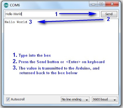
1. Once the Arduino sketch has been uploaded to the Arduino. Open the Serial monitor, which looks like a magnifying glass at the top right section of the Arduino IDE. Please note, that you need to keep the USB connected to the Arduino during this process, as the USB cable is your communication link between your computer and the Arduino.


2. Type anything into the top box of the Serial Monitor and press <Enter> on your keyboard. This will send a series of bytes to the Arduino. The Arduino will respond by sending back your typed message in the larger textbox.


3. Please note that we are using Serial.write(byteRead); on line 18 to get the Arduino to ECHO the message back to you on your computer. 


Things to Try 

1. Delete lines 16 to 18, and replace them with the following line :

               Serial.write(Serial.read());

This essentially eliminates the byteRead variable in the sketch above. But we will be using it later on, so once you have tested it out, put the code back together as originally displayed.


--------------------------------------------------------------------
2. Replace line 18 with a Serial.println instead of Serial.write

               Serial.println(byteRead);

Once uploaded, type 1 <enter> 2 <enter> 3 <enter>  into the Serial Monitor.
You should see:

49
50
51

Serial.print and Serial.println will send back the actual ASCII code, whereas Serial.write will send back the actual text. See ASCII codes for more information.


--------------------------------------------------------------------
3. Try typing in numbers like 1.5  or  2.003  or  -15.6 into the Serial Monitor using Serial.write and Serial.print or Serial.println commands as described before.

You will notice that the decimal point transmits as a number using Serial.print  or Serial.println, and will transmit as a decimal point when using Serial.write


STAGE 2: Delimiters                                                                                


How do you handle 2 or more numbers when sending or receiving?
Let us say that you have number pairs that you want the Arduino to interpret. How do you separate the numbers? The answer is Delimiters.
You may be familiar with CSV (comma separated value) files, where each field is separated by a comma (,). The comma is a useful way of separating or grouping information.

Lets say you have the following stream of numbers:
12345678910

How will your Arduino know if this is a single number, or a series of numbers?
Eg:

12,34,56,78,91,0
123,456,78,910
1,2,3,4,5,6,7,8,9,10
12345678910

The comma delimiters help to identify how the numbers should be interpreted.

 In the echo example in Stage 1 above, you would have noticed that when we used Serial.print(byteRead); that the values displayed one after another in a similar fashion to 12345678910.

You would have also noticed that Serial.println(byteRead); provided a line break between each value sent. And depending on the numbers sent, it could have looked like this:
12
34
56
78
91
0

The Serial.println() function essentially uses a line feed to separate the values being sent. This line break can be used as a delimiter, but we will look at that later on. For now we will concentrate on using a comma (,).

We will now get the Arduino to "listen" for the comma to help it identify a new number.
According to the ASCII code site, a comma is equal to byte code 44. So when the Arduino reads a byte code that is equal to 44, we will get it to print a line feed.


Enter the following sketch into your Arduino IDE and upload it to your Arduino.

Arduino Sketch


 1
2
3
4
5
6
7
8
9
10
11
12
13
14
15
16
17
18
19
20
21
22
23
24
25
26
27
/* Simple Serial ECHO script : Written by ScottC 04/07/2012 */
/* Stage 2 : Delimiters */

/* Use a variable called byteRead to temporarily store
the data coming from the computer */
byte byteRead;

void setup() {
// Turn the Serial Protocol ON
Serial.begin(9600);
}

void loop() {
/* check if data has been sent from the computer: */
if (Serial.available()) {
/* read the most recent byte */
byteRead = Serial.read();

/*Listen for a comma which equals byte code # 44 */
if(byteRead==44){
Serial.println();
}else{
/*ECHO the value that was read, back to the serial port. */
Serial.write(byteRead);
}
}
}
The above code was formatted using this site


Instructions

1. Once the code has been uploaded to the Arduino, open the Serial Monitor once again and type the following sequence of numbers:

1 <enter>  2 <enter> 3 <enter>

You should see the Serial monitor display the following number:    123


--------------------------------------------------------------------
2. While still in the serial monitor, type the following:

, <enter> 1 <enter> , <enter> 2 <enter> , <enter> 3 <enter> ,

Please note the commas between each numerical entry. You should now see a pattern like this:
1
2
3


--------------------------------------------------------------------
3. While still in the serial monitor, type the following:

12,23,34,45, <enter>

Please note the commas between each numerical entry. You should now see a pattern like this:
12
23
34
45

You will notice that the commas have been replaced by line feeds, and each number should display on a new line.


--------------------------------------------------------------------
4. While still in the serial monitor, type the following:

1,,2,,3, <enter>

You should see the following pattern:
1

2

3


So hopefully that explains the concept of delimiters and how they can be used to separate a stream of numbers, no matter how long it takes to get to the Arduino. We used an IF-statement to listen for the comma, but we could have used any other delimiter provided we knew the byte code.

We did not identify how to send delimiters FROM the Arduino, but we will get to that I promise. It is not that hard, and uses a similar principle. I am sure you can work it out, if not, stay tuned.


STAGE 3: Arduino Maths: Simple addition                                                  


In this stage, we are going to get the Arduino to do simple maths. We will send it two integers (or whole numbers), and the Arduino will do the hard work and send us the answer in no time at all.
This might seem like a simple task, but when you send a number like 27 to the Arduino, it does not receive the number 27. It receives 2 and then 7 in byte form. In other words, the Arduino will see the byte codes 50 and then 55 as per the ASCII table on this page.

One way to convert this byte code back to a 2 and a 7 is to subtract 48 from each byte received, providing the byte is in the range 48 to 57 inclusive (which equates to the numbers 0-9).
We are not done yet. We then need to join these numbers to make 27.

Step1: Subtract 48 from the bytes received, only if the bytes are in the range 48 to 57.
                 Example:    50 - 48 = 2
                                    55- 48 = 7

Step2: Multiply the previous number by 10, before adding the most recent byte received.
                 Example:   (2 x 10) + 7 = 27

If we have a number like 1928, then we would create this number using the following calculation
                                   1 =                         1
                   (1 x 10) + 9 =    10 + 9   =   19
                (19 x 10) + 2  = 190 + 2   =  192
              (192 x 10) + 8  = 1920 + 8 = 1928

Step3: Use a "+" sign as a delimiter so that the Arduino can move onto the Second number

Step4:  Capture the second number as per Step2. An "=" sign will tell the Arduino that it has reached the end of the second number, and to proceed to step 5.

Step5:  Add the 2 numbers together and send back the answer.


The following code will carry out the 5 steps above.
Enter the following sketch into your Arduino IDE and upload it to your Arduino.

Arduino Sketch


 1
2
3
4
5
6
7
8
9
10
11
12
13
14
15
16
17
18
19
20
21
22
23
24
25
26
27
28
29
30
31
32
33
34
35
36
37
38
39
40
41
42
43
44
45
46
47
48
49
50
51
52
53
54
55
56
57
58
59
60
61
62
63
64
/* Simple Serial ECHO script : Written by ScottC 05/07/2012 */
/* Stage 3: Arduino Maths: Simple Addition */

/* Global variables needed for programming workflow
byteRead: holds the value being read from the COM port
num1: holds the entire first number
num2: holds the entire second number
answer: holds the sum of num1 and num2
mySwitch: enables the switch between num1 and num2 */

byte byteRead;
long num1, num2,answer;
boolean mySwitch=false;

void setup() {
/* Turn the Serial Protocol ON and
initialise num1 and num2 variables.*/
Serial.begin(9600);
num1=0;
num2=0;
}

void loop() {
/* check if data has been sent from the computer: */
while (Serial.available()) {
/* read the most recent byte */
byteRead = Serial.read();

//listen for numbers between 0-9
if(byteRead>47 && byteRead<58){
//number found

/* If mySwitch is true, then populate the num1 variable
otherwise populate the num2 variable*/
if<!mySwitch)><br /> num1=(num1*10)+(byteRead-48);<br /> }<span>else</span>{<br /> num2=(num2*10)+(byteRead-48);<br /> }<br /> }<br /> <br /> <span>/*Listen for an equal sign (byte code 61) </span><br /><span> to calculate the answer and send it back to the</span><br /><span> serial monitor screen*/</span><br /> <span>if</span>(byteRead==61){<br /> answer=num1+num2;<br /> Serial.print(num1);<br /> Serial.print(<span>"+"</span>);<br /> Serial.print(num2);<br /> Serial.print(<span>"="</span>);<br /> Serial.println(answer);<br /> <br /> <span>/* Reset the variables for the next round */</span><br /> num1=0;<br /> num2=0;<br /> mySwitch=<span>false</span>;<br /> <br /> <span>/* Listen for the addition sign (byte code 43). This is</span><br /><span> used as a delimiter to help define num1 from num2 */</span> <br /> }<span>else</span> <span>if</span> (byteRead==43){<br /> mySwitch=<span>true</span>;<br /> }<br /> }<br />}<br /></pre></td></tr></tbody></table></div><br /><span>The above code was formatted using <a href="http://hilite.me/">this site</a></span><br /><br /><br /><h3> <u>Instructions</u></h3><br /><b>1.</b> Once the code has been uploaded to the Arduino, open the Serial Monitor once again and type the following sequence:<br /><br />         <span>1+2=   <enter></span><br /><br />You should get the following message sent back to Serial Monitor<br /><br />        <span> 1+2=3</span><br /><br /><br /><br /><h3> <b><u>Things to Try</u></b></h3><b>1.</b>   Enter this sequence: <br />              <span>10   <enter></span><br /><span>               +   <enter></span><br /><span>              10  <enter></span><br /><span>               =   <enter></span><br /><br />       Result:     <span>10+10=20</span><br /><br /><span>--------------------------------------------------------------------</span><br /><b>2. </b>  Enter this sequence:<br />            <span> 10  <enter></span><br /><span>             20  <enter></span><br /><span>             +5= <enter></span><br /><br /><br />      Result:  <span> 1020+5=1025</span><br /><br /><br /><br /><br /><span>--------------------------------------------------------------------</span><br /><b>3.</b>   Enter this sequence:<br />            <span> 10+20+30=   <enter></span><br /><br /><br />      Result:    <span>10+2030=2040</span><br /><br />I have specifically written this script to add <b>two</b> whole numbers together. If you start to introduce more complicated calculations, the results become unpredictable.<br /><br /><span>--------------------------------------------------------------------</span><br /><b>4.</b>    Enter this sequence:<br />           <span>1.2+1.0=    <enter></span><br /><br />      Result: <span>12+10=22</span><br /><br />Once again, I have only designed this script to handle whole numbers. Therefore, decimal points are ignored.<br /><br /><span>--------------------------------------------------------------------</span><br /><b>5.</b>  Enter this sequence:<br />         <span> -5 + 10=     <enter></span><br /><br /><br />     Result:    <span>5+10=15</span><br /><br /><br />This script ignores the negative sign, and treats the -5 as a positive 5.<br /><br /><br /><div>I have done this on purpose. I wanted to show you how the Arduino reads numbers from the com port, and how easy it is to exclude vital functionality in your code. I have kept this script simple, however, if you wanted to, you could make the Arduino deal with each of the above situations and more.  Multiplication, division and subtraction is handled in the same way. </div><br />This is the last thing I want you to try before we go to the next stage:<br /><br />6. Enter this sequence:<br />           <span>2147483646+1=  <enter></span>           Result:  <span>2147483646+1=2147483647</span><br />          <span> 2147483647+1=  <enter></span>           Result: <span>2147483647+1=</span><span>-</span><span>2147483648</span><br /><br /><br />Note that the maximum size of a "long" number is 2147483647. If you add one to this number, the result is equal to the minimum size of a "long" which is -2147483648.<br /><br /><br /><br /><br /><h3> <b><span><span>STAGE 4:  Sending doubles to Arduino</span> : <span>The double doubler</span>             </span></b></h3><div>Now we get to some tricky business. Sending and receiving Doubles (to and from) the Arduino.<br /><br />Up until now, I have tried to keep it simple using whole numbers, but there will come a time when you will want to send a fraction of a number through the Serial line.</div><div>To test our program, we will want to send a very small number to the Arduino, multiply the number by 2, and return it back.</div><div><br /></div><div>Our final test is to try a number like :  <b>0.000001</b></div><div>             and then a number like:<b>   123.321</b></div><div><br /></div><div><br /><b><span>IMPORTANT NOTE</span></b>:   When the Arduino sends a float or a double through the COM port using Serial.print() or Serial.println(), it will automatically send the number to 2 decimal places.<br />A number like 1.2345 will appear as 1.23,   and a number like 1.9996 will appear as 2.00<br />To demonstrate this, we will get the Arduino to send these floats/doubles to the Serial Monitor.<br /><br /><br /><div>Enter the following sketch into your Arduino IDE and upload it to your Arduino.</div><div><br /></div><h3> <u>Arduino Sketch</u></h3><br /><div><table><tbody><tr><td><pre><span><span> 1<br /> 2<br /> 3<br /> 4<br /> 5<br /> 6<br /> 7<br /> 8<br /> 9<br />10<br />11<br />12<br />13<br />14<br />15<br />16<br />17<br />18<br />19<br />20<br />21<br />22<br />23<br />24<br />25<br />26<br />27<br />28</span></span></pre></td><td><pre><span>/* Stage 4: Simple Transmission of a Double</span><br /><span> Written by ScottC on 7/7/2012 */</span><br /><br /><span>/* Declare the doubles that will be sent to the Serial Monitor */</span><br /> <span>double</span> myDub1, myDub2;<br /><br /><span>/* This part of the program only runs ONCE */</span><br /><br /> <span>void</span> setup(){<br /><br /> <span>/* Turn ON Serial Communication */</span><br /> Serial.begin(9600);<br /> <br /> <span>/* Assign a value 1.2345 and 1.9996 to the Doubles being sent */</span><br /> myDub1=1.2345;<br /> myDub2=1.9996;<br /> <br /> <span>/*Send the values to the Serial Monitor */</span><br /> Serial.print(<span>"myDub1 (1.2345) : "</span>);<br /> Serial.println(myDub1);<br /> Serial.print(<span>"myDub2 (1.9996) : "</span>);<br /> Serial.println(myDub2);<br /> }<br /><br /><br /> <span>void</span> loop(){<br /> <span>//Loop does nothing</span><br /> }<br /></pre></td></tr></tbody></table></div><span>The above code was formatted using </span><a href="http://hilite.me/">this site</a><br /><br />When you open the Serial monitor (after you have uploaded the sketch above), you will notice the following output:<br /><br /><br />         <span> myDub1 (1.2345) :</span> <span>1.23</span><br />         <span> myDub2 (1.9996) :</span> <span>2.00</span><br /><div><br /></div><br /><br />The <span>blue text</span> represents the string (or array of characters) being sent using lines 19 and 21.<br />The <span>red text</span> represents the actual double being sent using lines 20 and 22.<br /><br />You will notice that myDub2 rounds to 2.00.  This may or may not be what you want.<br />If you wish to increase the number of decimal places, then you will need to change lines 20 and 22 to the following:<br /><br /><span><span>20         Serial.println(myDub1,</span><span>4</span><span>)</span>;</span><br /><span><span>22         Serial.println(myDub2,</span><span>4</span><span>);</span></span><br /><br />The number 4 highlighted in red, indicates the number of decimal places you wish to send.<br />Try it ! And try changing this number to something bigger or smaller.<br /><br />---------------------------------------------------------------------------------------------------<br />Ok - now that we understand this little Serial.print(double,decimals) trick, we will now get the Arduino to echo back a Double.<br /><br />Before we jump in, perhaps we should try and map out our strategy. For this we will choose a simple decimal to make it easier. So in this example, we will choose <b>0.1</b></div><div>Once we get this working, we can then do our final test (as mentioned above).</div><div><br /></div><div>If we send 0.1 to the Arduino, it will read the following byte code</div><div><br /></div><div>48                    0</div><div>46                    .</div><div>49                    1</div><div><br /></div><div>We can use the decimal point as a delimiter.<br />We will use the following 5 steps to echo the double back to the Serial Monitor:</div><div><br /></div><div><b><span>Step1</span>:</b> Arduino collects all numbers before the decimal point using the same technique as in Stage3.<br /><br /></div><div><b><span>Step2</span>: </b>When the Arduino receives byte code 46, it will go into decimal mode.<br /><br /></div><div><b><span>Step3</span>:</b> The Arduino will collect numbers after the decimal point using a similar technique to step1.<br /><br /></div><div><b><span>Step4</span>:</b> Use maths to create the double, and then multiply it by 2<br /><br /></div><div><b><span>Step5</span>:</b> Display the doubled Double value in the Serial monitor.</div><div><br /></div><div><br /></div><div><br /><div>Enter the following sketch into your Arduino IDE and upload it to your Arduino.</div><div><br /></div><h3> <u>Arduino Sketch</u></h3></div><div><br /></div><div><table><tbody><tr><td><pre><span><span> 1<br /> 2<br /> 3<br /> 4<br /> 5<br /> 6<br /> 7<br /> 8<br /> 9<br />10<br />11<br />12<br />13<br />14<br />15<br />16<br />17<br />18<br />19<br />20<br />21<br />22<br />23<br />24<br />25<br />26<br />27<br />28<br />29<br />30<br />31<br />32<br />33<br />34<br />35<br />36<br />37<br />38<br />39<br />40<br />41<br />42<br />43<br />44<br />45<br />46<br />47<br />48<br />49<br />50<br />51<br />52<br />53<br />54<br />55<br />56<br />57<br />58<br />59<br />60<br />61<br />62<br />63<br />64<br />65<br />66<br />67<br />68<br />69<br />70<br />71<br />72<br />73<br />74<br />75<br />76<br />77<br />78<br />79<br />80<br />81<br />82<br />83<br />84<br />85</span></span></pre></td><td><pre><span>/* Simple Serial ECHO script : Written by ScottC 06/07/2012 */</span><br /><span>/* Stage 4: Double doubler */</span><br /><br /><span>/* Global variables needed for programming workflow</span><br /><span> ------------------------------------------------------</span><br /><span> byteRead: holds the value being read from the COM port</span><br /><span> num1: holds the number before the decimal point</span><br /><span> num2: holds the number after the decimal point</span><br /><span> complNum: holds the complete number (before multiplation)</span><br /><span> answer: holds the final value after multiplication</span><br /><span> counter: is used to convert num2 to the number after the decimal</span><br /><span> numOfDec: counts the numbers after the decimal point</span><br /><span> mySwitch: enables the switch between num1 and num2 */</span><br /> <br /> byte byteRead;<br /> <span>double</span> num1, num2;<br /> <span>double</span> complNum,answer,counter;<br /> <span>int</span> numOfDec;<br /> boolean mySwitch=<span>false</span>;<br /><br /><br /> <span>void</span> setup() { <br /><span>/* Turn the Serial Protocol ON and </span><br /><span> initialise num1 and num2 variables.*/</span><br /> Serial.begin(9600);<br /> num1=0;<br /> num2=0;<br /> complNum=0;<br /> counter=1;<br /> numOfDec=0;<br /> }<br /><br /> <span>void</span> loop() {<br /><span>/* check if data has been sent from the computer: */</span><br /> <span>while</span> (Serial.available()) {<br /> <span>/* read the most recent byte */</span><br /> byteRead = Serial.read();<br /> <br /> <span>//listen for numbers between 0-9</span><br /> <span>if</span>(byteRead>47 && byteRead<58){<br /> <span>//number found</span><br /> <br /> <span>/* If mySwitch is true, then populate the num1 variable</span><br /><span> otherwise populate the num2 variable*/</span><br /> <span>if</span><!mySwitch)><br /> num1=(num1*10)+(byteRead-48);<br /> }<span>else</span>{<br /> num2=(num2*10)+(byteRead-48);<br /> <br /> <span>/* These counters are important */</span><br /> counter=counter*10;<br /> numOfDec++;<br /> }<br /> }<br /> <br /> <span>/*Listen for an equal sign (byte code 61) </span><br /><span> to calculate the answer and send it back to the</span><br /><span> serial monitor screen*/</span><br /> <span>if</span>(byteRead==61){<br /> <span>/* Create the double from num1 and num2 */</span><br /> complNum=num1+(num2/(counter));<br /> <br /> <span>/* Multiply the double by 2 */</span> <br /> answer=complNum*2;<br /> <br /> <span>/* Send the result to the Serial Monitor */</span> <br /> Serial.print(complNum,numOfDec);<br /> Serial.print(<span>" x 2 = "</span>);<br /> Serial.println(answer,numOfDec);<br /> <br /> <span>/* Reset the variables for the next round */</span><br /> num1=0;<br /> num2=0;<br /> complNum=0;<br /> counter=1;<br /> mySwitch=<span>false</span>;<br /> numOfDec=0;<br /> <br /> <span>/* Listen for the decimal point (byte code 46). This is</span><br /><span> used as a delimiter to help define num1 from num2 */</span> <br /> }<span>else</span> <span>if</span> (byteRead==46){<br /> mySwitch=<span>true</span>;<br /> }<br /> }<br /> }<br /></pre></td></tr></tbody></table></div><div><span>The above code was formatted using </span><a href="http://hilite.me/">this site</a></div><div><br /></div><div><br /></div><div><br /><h3> <b><u>Things to Try</u></b></h3><div><b><u><br /></u></b></div><div>1. Type the following into the serial monitor:</div><div><br /></div><div>       <span>1.2=  <enter></span>                             Result:   <span>1.2 x 2 = 2.4</span></div><div><br /></div><div>Make sure that you type the equal sign (=) before you press enter, otherwise the Arduino will not know that you are finished, and will not send anything back.</div><div><br /></div><div>--------------------------------------------------------------------</div><div>2. Type the following into the serial monitor:</div><div><br /></div><div>      <span>100.001=  <enter></span>                      Result:   <span>100.001 x 2 = 200.002</span></div><div><br /></div><div>You will notice that the Arduino is formatting the decimal to the SAME number of decimals as that entered.</div><div>This is controlled by the variable: <span>numOfDec</span>.</div><div>---------------------------------------------------------------------</div><div>3. Now for our final test: Type the following into the serial monitor:</div><div><br /></div><div>   <span> 0.000001= <enter></span>                       Result: <span>0.000001 x 2 = 0.000002</span></div><div><br /></div><div>First test:<span> PASSED</span></div><div><br /></div><div>----------------------------------------------------------------------</div><div>4. Type the following into the Serial monitor for our last test:</div><div><br /></div><div>     <span>123.321=  <enter></span>                      Result: <span>123.321 x 2 = 246.642</span></div><div><br /></div><div>Second test: <span>PASSED</span></div><div>-----------------------------------------------------------------------</div><div><br /></div><div><span>BEWARE</span>: While everything looks perfect, let me tell you that it isn't. But hopefully this code will help you get on the right track. If you decide to type in a number like 123123.111222, you will not get the answer you expected. </div><div>I have found that this program will work if the amount of numbers before and after the decimal point are less than about 9.  Eg. 1234.1234   will produce the right result.</div><div>However, 11111.2222 will NOT, because there are 9 numbers represented.</div><div><br /></div><div>I think this has something to do with the memory allocated to a double, but I am not sure. </div><div>I don't know if people work with these types of numbers, but I am sure there is a workaround, and I am sure someone out there can work it out. I don't personally need this kind of precision, but thought to mention it just in case you do.</div><div><br /></div><div><br />----------------------------------------------------------------------- <br />----------------------------------------------------------------------- <br /><br /><h3> <b><span><span>STAGE 5:  Sending sensor data to the Serial Monitor</span>             </span></b></h3><br /><br />We know the Arduino is very good at copy-Cat games, how about getting the Arduino to send us some data from one of our sensors. We will use the Serial Monitor to view the sensor data.<br /><br />Disconnect the USB cable, and hook up one of your favourite analog sensors to your Arduino. For simplicity, I am going to hook up a potentiometer as per the Fritzing sketch below.<br /><br /><h3> <u> Parts Required</u></h3><br /><ul><li>Arduino UNO (or equivalent)</li><li>Computer with USB cable</li><li>Breadboard</li><li>Potentiometer</li><li>3 Wires</li></ul><div><br /></div><br /><h3> <u> Arduino Fritzing Sketch</u></h3><br /></div><div><div><a href="http://1.bp.blogspot.com/-JZlWUi3MDck/T_g6ldkqSVI/AAAAAAAAAPY/_UJj4EU3YYE/s1600/Fritzing_Potentiometer_Sketch.jpg"><img src="http://1.bp.blogspot.com/-JZlWUi3MDck/T_g6ldkqSVI/AAAAAAAAAPY/_UJj4EU3YYE/s400/Fritzing_Potentiometer_Sketch.jpg" /></a></div><br /></div><div><br /></div><div>     </div><div><br /></div><div><br /></div></div><br /><br /><br /><br /><br /><br /><br /><br /><br /><br /><br /><br /><br /><br /><br /><br /><br />Once you have attached your sensor to the board, plug your USB cable into the Arduino, and upload the following sketch.<br /><br /><br /><h3> <u>Arduino Sketch</u></h3><div><u><br /></u></div><div><table><tbody><tr><td><pre><span><span> 1<br /> 2<br /> 3<br /> 4<br /> 5<br /> 6<br /> 7<br /> 8<br /> 9<br />10<br />11<br />12<br />13<br />14<br />15<br />16<br />17<br />18<br />19<br />20<br />21</span></span></pre></td><td><pre> <span>/* Stage 5: Send Sensor Value to Serial Monitor</span><br /><span> Written by ScottC on 7/7/2012 */</span><br /><br /> <span>int</span> sensorVal = 0; <br /><br /> <span>void</span> setup() {<br /> <span>// Setup Serial communication with computer</span><br /> Serial.begin(9600);<br /> }<br /><br /> <span>void</span> loop() {<br /> <span>// Read the value from the sensor:</span><br /> sensorVal = analogRead(A0);<br /> <br /> <span>// Send the value to the Serial Monitor</span><br /> Serial.print(<span>"Sensor Value="</span>);<br /> Serial.println(sensorVal);<br /><br /> <span>// Interval between readings = 1 second</span><br /> delay(1000); <br /> }<br /></pre></td></tr></tbody></table></div><div><span>The above code was formatted using </span><a href="http://hilite.me/">this site</a><br /><u><br /></u><br /><u><br /></u><br /><h3> <u>Instructions</u></h3></div></div></div><div>1. Open the Serial monitor and watch the readings change depending on the input conditions. In my case, by turning the potentiometer from left to right, I get an output similar to the picture below.</div><div><br /></div><div><a href="http://2.bp.blogspot.com/-F8H8h8YkXJo/T_g_dcPTN1I/AAAAAAAAAPk/AXQaR5x_UFk/s1600/Serial+Monitor.jpg"><img src="http://2.bp.blogspot.com/-F8H8h8YkXJo/T_g_dcPTN1I/AAAAAAAAAPk/AXQaR5x_UFk/s400/Serial+Monitor.jpg" /></a></div><div><br /></div><div><br /></div><div><br /></div><div><br /></div><div><br /></div><div><br /></div><div><br /></div><div><br /></div><div><br /></div><div><br /></div><div><br /></div><div><br /></div><div><br /></div><div><br /></div><div><br /></div><div><br /></div><div><br /></div><div><br /></div><div><br /></div><div>As per the Arduino reference site, <a href="http://arduino.cc/en/Reference/analogRead">AnalogRead</a> returns an integer between 0 and 1023. You can see this is true based on the picture above. But what if we do not want a value between 0 and 1023. Let us say we want a value between 0 and 100?</div><div><br /></div><div>You would have to use the <a href="http://arduino.cc/en/Reference/Map">map function</a>. We will do it by changing line 13 to this:</div><div><br /></div><div><pre><span><span>13</span></span><span> </span><span><span><b>sensorVal = map(analogRead(A0),0,1023,0,100);</b></span></span></pre></div><div><br /></div><div>The map function is quite a cool function, and good fun to play around with. So here are some things to try.</div><div><h3> <b><u>Things to Try</u></b></h3></div><div>1. Change line 13 to the following, upload to the Arduino </div><div>    and then open the Serial Monitor to see the effect.</div><div><br /></div><div><b><span>Trial 1</span></b>:</div><div><pre><span><span>13</span></span><span> </span><span><span><b>sensorVal = map(analogRead(A0),0,1023,100,0);</b></span></span></pre></div><div><br /></div><div><div><b><span>Trial 2</span></b>:</div><div><pre><span><span>13</span></span><span> </span><span><span><b>sensorVal = map(analogRead(A0),0,1023,0,1000);</b></span></span></pre></div></div><div><br /></div><div><div><span><b>Trial 3</b></span>:</div><div><pre><span><span>13</span></span><span> </span><span><span><b>sensorVal = map(analogRead(A0),200,800,0,100);</b></span></span></pre></div></div><div><br /></div><div><br /></div><div>In <b><span>Trial 1</span></b>: We see that the values have been inverted. Instead of ranging from 0 up to100, they now go from 100 down to 0.</div><div><br /></div><div>In <b><span>Trial 2</span></b>: The analog readings are now mapped to a range of 0 up to 1000. </div><div><br /></div><div>In <b><span>Trial 3</span></b>: The analog readings that range from 200 to 800 are mapped to a range of 0 to 100. Therefore if the analog readings drop below 200, we will end up with a negative value for sensorVal. </div><div>If the analog readings go above 800, we will end up with a value greater than 100.  For this particular example, my readings actually range from  -33 to 137.</div><div><br /></div><div>Therefore an Analog reading of 0 = -33</div><div>                 Analog reading of 200 = 0</div><div>                 Analog reading of 800 = 100</div><div>               Analog reading of 1023 = 137</div><div><br /></div><div><br /></div><div>----------------------------------------------------------------------------------</div><div>What if we don't want the output to go beyond our intended limits of 0 to 100?</div><div>Then you would have to use the <a href="http://arduino.cc/en/Reference/Constrain">constrain function</a>. This essentially trims the reading range of the sensor, and sets a minimum and maximum value.</div><div><br /></div><div>Replace line 13 with the following code:</div><div><br /></div><div><pre><span><span>13</span></span><span> </span><span><span><b>sensorVal = constrain(map(analogRead(A0),200,800,0,100),0,100);</b></span></span></pre></div><div><br /></div><div><div>Therefore an Analog reading of 0 = 0</div><div>                 Analog reading of 100 = 0</div><div>                 Analog reading of 200 = 0</div><div>                 Analog reading of 800 = 100</div><div>                  Analog reading of 955 = 100</div><div>               Analog reading of 1023 = 100</div></div><div>Analog values between 200 and 800 will produce a result between 0 and 100.</div><div><br /></div><div>-------------------------------------------------------------------------------------<br /><br /><h3><span>If you wish to continue with this tutorial (stage 6 and above), please follow this link:  <a href="http://arduinobasics.blogspot.com/2012/07/arduino-basics-simple-arduino-serial_09.html">Serial Communication Stage 6 and above</a> </span></h3></div><div><br /></div><div><br /></div> <br />  <br />  <div> <p> <!--separator --> <img src="https://images-blogger-opensocial.googleusercontent.com/gadgets/proxy?url=http%3A%2F%2F1.bp.blogspot.com%2F-XQiwNpdqOxk%2FT_rKCzDh4nI%2FAAAAAAAAAQY%2FOfYBljhU6Lk%2Fs1600%2FSeparator.jpg&container=blogger&gadget=a&rewriteMime=image%2F*" /><br /> <br /> </p> </div> <p> <div> <p> If you like this page, please do me a favour and show your appreciation : <br /> <br />  <br /> Visit my <a href="https://plus.google.com/u/0/b/107402020974762902161/107402020974762902161/posts">ArduinoBasics Google + page</a>.<br /> Follow me on Twitter by looking for <a href="https://twitter.com/ArduinoBasics">ScottC @ArduinoBasics</a>.<br /> I can also be found on <a href="https://www.pinterest.com/ArduinoBasics/">Pinterest</a> and <a href="https://instagram.com/arduinobasics">Instagram</a>. <br /> Have a look at my videos on my <a href="https://www.youtube.com/user/ScottCMe/videos">YouTube channel</a>.<br /> </p></div> <div> <p>              <a href="http://arduinobasics.blogspot.com.au/p/arduino-basics-projects-page.html"><img src="http://2.bp.blogspot.com/-4b59S-y-Tws/VYeJtC1HNyI/AAAAAAAABk4/_CWyTKOPYOw/s320/ArduinoBasics_OpenLogo%2Bon%2BBlack.png" /></a> </p></div> <div> <p> <img src="https://images-blogger-opensocial.googleusercontent.com/gadgets/proxy?url=http%3A%2F%2F1.bp.blogspot.com%2F-XQiwNpdqOxk%2FT_rKCzDh4nI%2FAAAAAAAAAQY%2FOfYBljhU6Lk%2Fs1600%2FSeparator.jpg&container=blogger&gadget=a&rewriteMime=image%2F*" /><br /> <br /> </p></div> <div> <p> However, if you do not have a google profile... <br />Feel free to share this page with your friends in any way you see fit. </p></div></p>