Tiny, Hackable Telepresence Robot for under $100? Meet Goby
[Charmed Labs] are responsible for bringing numerous open-source hardware products to fruition over the years, and their latest device is an adorably small robotic camera platform called Goby, currently crowdfunding for its initial release. Goby has a few really clever design features and delivers a capable (and hackable) platform for under 100 USD.
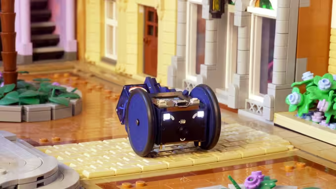
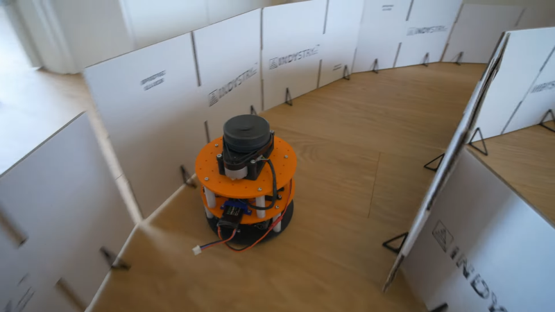
Goby embraces its small size, delivering what its creators dub “tinypresence” — or the feeling of being there, but on a very small scale. Cardboard courses, LEGO arenas, or even tabletop gaming scenery hits different when experienced from a first-person perspective. Goby is entirely reprogrammable with nothing more than a USB cable and the Arduino IDE, while costing less than most Arduino starter kits.
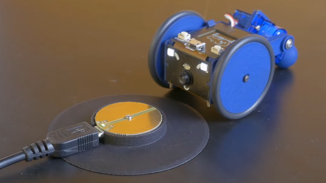
One of the physical features we really like is the tail-like articulated caster at the rear. Flexing this pivots Goby up or down (and can even flip Goby completely over), allowing one to pan and tilt the view without needing to mount the camera on a gimbal. It also comes into play for recharging; Goby simply moves over the disc-shaped charger and pivots down to make contact.
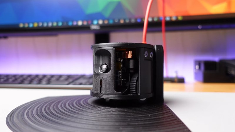
At Goby‘s heart is an ESP32-S3 and OmniVision OV2640 camera sensor streaming a live video feed (and driving controls) with WebRTC. Fitting the WebRTC stack onto an ESP32 wasn’t easy, but opens up possibilities beyond just media streaming.
Goby is set up to make launching an encrypted connection as easy as sharing a URL or scanning a QR code. The link is negotiated between bot and client with the initial help of an external server, and once a peer-to-peer connection is established, the server’s job is done and it is out of the picture. [Charmed Labs]’s code for this functionality — named BitBang — is in beta and destined for an open release as well. While BitBang is being used here to make it effortless to access Goby remotely, it’s more broadly intended to make web access for any ESP32-based device easier to implement.
As far as tiny remote camera platforms go, it might not be as small as rebuilding a Hot Wheels car into a micro RC platform, but it’s definitely more accessible and probably cheaper, to boot. Check it out at the Kickstarter (see the first link in this post) and watch it in action in the video, embedded just below the page break.
 nRF24L01 boards and build yourself a copy of the remote control [saul] handily provides in