Posts with «github» label

Arduino and Git: Two Views

You can’t do much development without running into Git, the version control management system. Part of that is because so much code lives on GitHub which uses Git, although you don’t need to know anything about that if all you want to do is download code. [Dr. Torq] has a good primer on using Git with the Arduino IDE, if you need to get your toes wet.

You might think if you develop by yourself you don’t need something like Git. However, using a version control system is a great convenience, especially if you use it correctly. There’s a bug out in the field? What version of the firmware? You can immediately get a copy of the source code at that point in time using Git. A feature is broken? It is very easy to see exactly what changed. So even if you don’t work in a team, there are advantages to having source code under control.

If you are already using a more advanced IDE, Git is probably integrated into your environment, or, at least, it could be. If you are allergic to the command line, there are plenty of GUI tools to use Git, also. One nice thing about Git is that your local repository is just a directory. You don’t need to stand up a special server or anything to use it.

We don’t think it is directly related, but [Andreas] recently had a video on Git and Arduino. It isn’t as detailed, but it does have some good stuff and is worth the time to watch. You can see it below.

We’ve used Git for some odd things in the past. Note that Git is the version control system while GitHub is a website. However, if you are a hardcore command line user, you can manipulate GitHub from there, too.

Arduino on GitHub Actions

This post is from Massimiliano Pippi, Senior Software Engineer at Arduino.

GitHub Actions is the name of the SDLC (Software Development Life Cycle) system introduced by GitHub about a year ago, currently in public beta and now approaching the general availability status. When you read SDLC, think about some sort of CI/CD system that’s generic enough to let you define a sequence of operations not necessarily limited to build, test, and deploy code: GitHub Actions can help you automate processes in code reviews, issue triaging, and repository management.

GitHub Actions have been part of the tools we use at Arduino for a while now; helping us solve a wide range of problems from automating workflows within our backend infrastructure, to managing the release process of our open source software. In the spirit of giving back to the community, we started publishing some of the Actions we developed internally so that they can be used right ahead from any GitHub account that’s been granted access to the public beta of GitHub Actions, and eventually in any GitHub repository.

Our Actions are available from this repository and there’s one in particular we think the Arduino community will be happy to have – it’s called setup-arduino-cli and under the hood it takes all the steps necessary to have the `arduino-cli` binary available in a Workflow.  This means that in any step of your Workflow you can leverage the long list of features of the Arduino CLI.

# This is the name of the workflow, visible on GitHub UI.
name: test
 
# Here we tell GitHub to run the workflow when a commit
# is pushed or a Pull Request is opened.
on: [push, pull_request]
 
# This is the list of jobs that will be run concurrently.
# Since we use a build matrix, the actual number of jobs
# started depends on how many configurations the matrix
# will produce.
jobs:
  # This is the name of the job - can be whatever.
  test-matrix:
 
    # Here we tell GitHub that the jobs must be determined
    # dynamically depending on a matrix configuration.
    strategy:
      matrix:
        # The matrix will produce one job for each configuration
        # parameter of type arduino-platform, in this case a
        # total of 2.
        arduino-platform: ["arduino:samd", "arduino:avr"]
        # This is usually optional but we need to statically define the
        # FQBN of the boards we want to test for each platform. In the
        # future the CLI might automatically detect and download the core
        # needed to compile against a certain FQBN, at that point the
        # following include section will be useless.
        include:
          # This works like this: when the platform is "arduino:samd", the
          # variable fqbn is set to "arduino:samd:nano_33_iot".
          - arduino-platform: "arduino:samd"
            fqbn: "arduino:samd:nano_33_iot"
          - arduino-platform: "arduino:avr"
            fqbn: "arduino:avr:uno"
 
    # This is the platform GitHub will use to run our workflow, we
    # pick Windows for no particular reason.
    runs-on: windows-latest
 
    # This is the list of steps this job will run.
    steps:
      # First of all, we clone the repo using the checkout action.
      - name: Checkout
        uses: actions/checkout@master
 
      # We use the arduino/setup-arduino-cli action to install and
      # configure the Arduino CLI on the system.
      - name: Setup Arduino CLI
        uses: arduino/setup-arduino-cli@v1.0.0
 
      # We then install the platform, which one will be determined
      # dynamically by the build matrix.
      - name: Install platform
        run: |
          arduino-cli core update-index
          arduino-cli core install ${{ matrix.arduino-platform }}
 
      # Finally, we compile the sketch, using the FQBN that was set
      # in the build matrix.
      - name: Compile Sketch
        run: arduino-cli compile --fqbn ${{ matrix.fqbn }} ./blink

Example

Let’s say you keep your sketches in a GitHub repository, and you want to be sure that every time you push a git commit or you merge a pull request, the sketches compile correctly on certain boards you own, for example a Nano 33 IoT and a Uno. To keep the configuration at minimum, we can use a “build matrix”, so that GitHub will start a different job for each one of the platforms we list in the matrix, without the need to configure them explicitly.

You can find a working example here: https://github.com/arduino/arduino-cli-example

You can find more info and docs for the Action on the GitHub Marketplace: if you like it, please leave us a star!
We’re eager to hear your feedback, feel free to hit the Action repository and open an issue should you find any problem, or a feature request in case you want more from the action.

Arduino Blog 14 Nov 11:32

Blue Pill Makes Cheap But Powerful Morse Tutor

[W8BH] attended a talk by another ham, [W8TEE] that showed a microcontroller sending and receiving Morse code. He decided to build his own, and documented his results in an 8 part tutorial. He’s using the Blue Pill board and the resulting device sends code with paddles, sends canned text, provides an LCD with a rotary knob menu interface, and even has an SD card for data storage.

All the code is on GitHub. If you are interested in Morse code or in learning how to write a pretty substantial application using the Blue Pill and the Arduino IDE (or any other similar processor), this is a great exposition that is also a practical tool.

[W8BH] takes good advantage of breakout boards with things such as the displays and jacks on them. Of course, you don’t absolutely have to use those, but it does make life easier. You can see [W8TEE’s] version posted in an online forum.

The parts of the tutorial all build on each other, so you start out simple and get deeper and deeper. The tutorials are PDF files, but they are well organized and easy to read.

We’ve done our tutorials and videos on the Blue Pill. If you don’t want to rely on the Arduino IDE, there are ways around that, too.

Blue Pill header pic: Popolon [CC BY-SA 4.0]

Hack a Day 08 Aug 03:00

Hands on with the Arduino FPGA

All of the tools you need to work with the FPGA Arduino — the Vidor — are now in the wild!

We reported earlier that a series of French blog posts finally showed how all the pieces fit together to program the FPGA on the Arduino MKR4000 Vidor board. Of course, I wasn’t content to just read the Google translation, I had to break out the board and try myself.

I created a very simple starter template, a tool in C to do the bitstream conversion, required, and bundled it all together in one place. Here’s how you can use my starter kit to do your own FPGA designs using the Vidor. I’m going to assume you know about FPGA basics and Verilog. If you don’t, why not check out the FPGA boot camps first?

The first thing you’ll want to do is grab my GitHub repo. You’ll also need the Arduino IDE (a recent copy) and Intel’s Quartus software. Inside, you’ll find three directories, two of which contain slightly modified copies of original Arduino files. But before you start digging in, let’s get the high-level overview of the process.

Basic Concepts
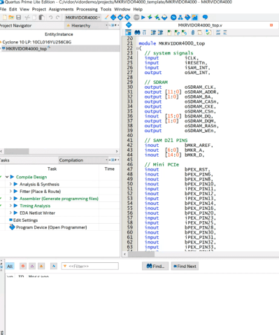
The FPGA onboard the Vidor is an Intel/Altera device so to configure it, we’ll use Quartus. Usually, Quartus handles everything including programming the device, but we can’t use it for that with the Vidor. Instead, we will have to tell the CPU how we want the FPGA configured and it will do it for us as part of our Arduino program (I really hate saying sketch).

Quartus (see below) will take our Verilog files and create a ttf file that represents the configuration bitstream. This is just an ASCII text file full of decimal numbers. Unfortunately, the way the Vidor is set up, it needs the numbers bit reversed at the byte level. That is, 01 in the ttf file needs to be 80 hex sent to the FPGA.

Arduino supplies a Java class file to do the task, but I got frustrated because the class file needed Java 11 and I didn’t want to put it on every machine I use, so I just rewrote it in C. It is easy enough to port the algorithm, though. In the shell subdirectory, I have another example implementation using awk.

Once you have this stream of numbers, you can include it in an Arduino sketch with some boilerplate to enable the FPGA and load it. The standard program includes the file app.h which is just the output of the conversion program. There’s no C code in it, just comma-separated numbers that the main code will stick in an array at compile-time. Beyond that, it is a normal Arduino program and you can do what you like. Upload it and you’ll get the CPU and FPGA programmed all in one go.

There is one caveat. The FPGA code has a top-level block with lots of I/O pins defined and the corresponding constraints. You should be very careful not to change these or alter the pin constraints. If you drive a pin that’s already an output, for example, you could do real harm to the board. Because all the pins are shared, you have the same problem with the Arduino pins, too. If you are driving an output pin with the FPGA, you shouldn’t try to drive it with the CPU also. However, as you will see, it is perfectly fine to have the FPGA reading a pin from the CPU or vice versa. That’s good because it gives us a way to send data back and forth between them.

On to Code

I wanted something simple, and I didn’t want to accidentally modify the Arduino boilerplate Verilog. You could instantiate a Verilog module, but this would require passing all the I/O pins into the module or modifying the original code every time, both of which I wanted to avoid.

My answer was to use the Verilog `include directive inside the boilerplate. That way your code has access to everything the main module has, but you don’t have to change the main module. The only downside is that Quartus has a smart compile feature that can’t figure out when only an include file changes. So it wasn’t recompiling when I made changes. I turned that feature off in the Quartus options, so if you pick up my example project, you won’t have any problems.

Here’s my example user.v:

reg [27:0] hadcounter;
assign bMKR_D[6]=bMKR_D[5]?hadcounter[27]:hadcounter[21];

always @(posedge wOSC_CLK)
begin
   if (!rRESETCNT[5])
   begin
      hadcounter<=28'hfffffff;
   end
   else
   begin
      if (hadcounter==28'h0) hadcounter<=28'hffffffff; else hadcounter<=hadcounter-28'h1;
   end
end

In the real file, I left a lot of comments in that explains what all the main module has that you can use. But the above is the working part. I define a 28 bit counter. The bMKR_D array is the digital ports for the Arduino and I’m using pin 6 and 5 as an output and an input, respectively.

The assign statement says, in English, If D5 is high, connect the 27th bit of the counter to the LED. If it is low, connect the 21st bit. The rest of the code just makes the counter countdown. I reload the counter even though it would naturally roll over in case you want to fine tune it to a different frequency.

As the counter runs, bit 27 will toggle relatively slowly, but bit 21 will be a good bit faster — that’s just how a counter is. So by changing D5 you can make the LED blink slow or fast.

As Verilog goes, this isn’t very complicated or even useful, but it is simple and shows that we can share data with the CPU in both directions. If you open the example project in Quartus, all you really need to do is make any changes to user.v you like, add any other files you want to use and double-click the Compile Design task (see left). If you get a successful compile, you’ll find the ttf file in the output_files directory. That’s the file you need to process with either the Java program, the C program, or the awk script. Either way, collect the output as app.h and put it in the same directory as your Arduino code.

CPU Side

On the sketch side, you need to leave the template code alone since it turns on the FPGA clock, among other things. You’ll notice it also includes app.h and uses a file called jtag.c to communicate with the FPGA. I didn’t segregate the Arduino code into its own include because you probably have to change the setup function, and make changes in global space, but that could be arranged (perhaps make setup call cpu_setup and loop call cpu_loop or something).

If you want to remove the demo parts of the blink-sketch file, you can get rid of:

  • The definitions and calls related to FPGAVal, SPEED, and FPGALED
  • The Serial calls and definitions
  • Everything in the loop function

I left the unmodified code in the EmptySketch directory. Note in the demo code, though that SPEED is an output. This is set to D5, which is an input to the FPGA. By the same token, FPGALED corresponds to D6 and allows the CPU to read the state of the LED output.
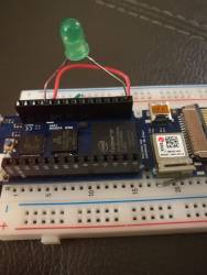
You will need an LED and dropping resistor on pin 6 unless you want to watch with a scope or a meter. I always keep some LEDs with built-in 5V dropping resistors handy, and even at 3.3V it was plenty bright. With one of those, you can just stick the wires right into the header socket on the board. Don’t try that with a regular LED, though!

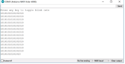
Once you run the sketch, you can open the serial monitor or any terminal at 9600 baud. There will be a message saying you can press any key to change the blink rate. Of course, since the serial monitor doesn’t allow you to press keys exactly, you’ll have to enter something and hit enter (set “No line ending” at the bottom of the monitor screen), but on a real terminal, any character press should do it.

The main code is pretty simple:

void loop() {
static int oldstate=-1;
static int linect=0;
int state;
if (Serial.read()!=-1)
  {
  FPGAVal=FPGAVal==HIGH?LOW:HIGH;
  digitalWrite(SPEED,FPGAVal);
  }
state=digitalRead(FPGALED);
if (state!=oldstate)
  {
  Serial.print(state);
  if (++linect==16)
    {
    Serial.println();
    linect=0;
    }
  oldstate=state;
  }
}

In the loop, if serial data appears, we just toggle the output going to the FPGA. We also sample the LED output on every pass. If it has changed from the last time, we write the new state to the terminal and then update the state so we don’t flood the screen with repeated characters. A lot of the code is just tracking when we’ve written enough to start a new line.

Vidor’s Hello World

I wanted to get everything you needed in one place and an example that would be easy to follow yet show the critical working parts. It would be easy enough to use the shared I/O pins to do SPI, for example, and then you could trade data with the FPGA quite easily. Don’t forget there’s Arduino IP (intellectual property; sort of library subroutines for FPGAs) in the IP directory, too, if you want to use it.

Now you just need a project idea that makes sense for an FPGA. Our personal favorite would be a logic analyzer. The CPU can talk to the PC, set up triggers and then let the FPGA do the dirty work of finding the trigger and storing data as fast as possible. If you want something less ambitious, it is very simple to create totally autonomous PWM outputs on an FPGA. We could see this being handy for robotics or machine control where you want a very rapid sequence of outputs without CPU intervention or overhead.

Of course, not every project has to make sense. If you are just wanting to learn about FPGAs there are plenty of projects you could do with a CPU but are easy enough to build in an FPGA (the classic traffic light comes to mind). Of course, with the Vidor you have an opportunity to use a blend of FPGA code and CPU code, which is kind of the point.
Turning a toy piano into a standalone digital synthesizer

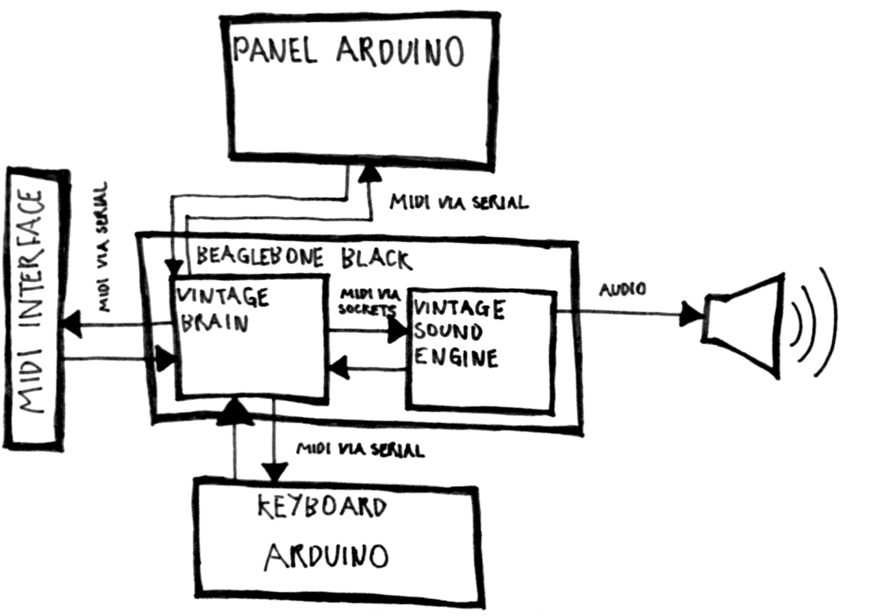
Electronic musical instruments are fun for Makers. With some cheap tools, know-how and passion, anyone can become a real synth geek. Just ask software developer Liam Lacey, who also happens to be a sound coder and freelance hacker. He recently won element14’s Open Source Music Tech design challenge for his Vintage Toy Synthesizer project — it’s an acoustic wooden toy piano converted into an open-source, standalone polyphonic digital synthesizer running on a BeagleBone Black and an Arduino Pro Mini.

Playing an instrument is about a lot more than just the sound you create – the way you play it; the physical feedback; and the overall feel and aesthetics of the instrument also play a big role in the overall experience, with these elements also helping to nurture inspiration, and can even affect your perception of the sound created.

Lacey developed the voice engine using the C++ audio DSP library Maximilian, and the keyboard mechanism uses homemade pressure sensors made out of Velostat. The instrument has 18 keys, with players able to also alter scales using the knobs on top of the mini piano’s lid.

Other dials are used to toggle dedicated waveform oscillators, various filters and onboard distortion effects, and there’s even vintage parameters for replicating old or broken analog synth voices. What’s neat is that the converted toy can also act as a MIDI controller to send velocity-sensitive note messages and polyphonic aftertouch to Logic Pro, Ableton Live and various music software programs.

Here’s a diagram of the software architecture of the synth:

You can read more about the hack here, as well as listen to some quick and rough sound/patch demos:

The project took three and a half months to bring to fruition, and let us just say, the final result is quite impressive! Check out the video below to learn more about  its specs and explore the complete documentation on GitHub.


Atomic Arduino (and Other) Development

Even the most die-hard Arduino fan boys have to admit that the Arduino development environment isn’t the world’s greatest text editor (they’d probably argue that its simplicity is its strength, but let’s ignore that for now). If you are used to using a real code editor, you’ll probably switch to doing your Arduino coding in that and then use the external editor integration in the IDE.

That works pretty well, but there are other options. One we noticed, PlatformIO, extends GitHub’s Atom editor. That makes it cross-platform, powerful, and with plenty of custom plug ins. It also supports a range of platforms including Arduino, many ARM platforms, MSP430, and even desktop computers running Linux or Windows.

The author claims the plug in will generate code for over 200 embedded boards. It handles all the common development tasks and even includes a terminal window. There are command line tools if you want to build scripts or make files and bypass the GUI.

You can install Platform.io on Windows, Linux, or Mac. It uses Python, so porting it elsewhere might be easy, too. The feature list is broad: code completion, linting, multiple projects, and library management. It can even import projects from the Arduino IDE. There are plenty of plug ins to add features (like Emacs keybindings, although that took a little troubleshooting).

There is also something attractive about having a single IDE that targets different platforms if you switch back and forth a lot. In all fairness, the Arduino IDE isn’t as bad as it used to be, and they both have significantly improved versions in the works (Arduino Create and Arduino Studio). We’ve seen plenty of other IDE hacks for Arudino in the past.

Thanks for the tip [Martin]


Filed under: Arduino Hacks
Hack a Day 23 Apr 18:00

Arduino IDE 1.6.6 released and available for download

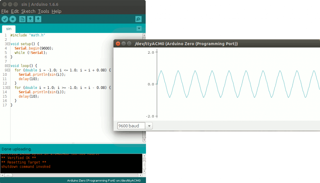
Today we are very proud to release Arduino IDE 1.6.6 and updated cores for all supported platforms (AVR 1.6.9, SAM 1.6.5, SAMD 1.6.2)

This update brings an impressive 723 closed issues and 147 pull requests merged.

Most intriguing features are:

  • Long-awaited new arduino-builder: this is a pure command-line tool which takes care of mangling the code, resolving library dependencies and setting up the compilation units. It can also be used as a standalone program in a continuous-integration environment
  • Pluggable USB core: your Arduino can finally act as a lot of different USB devices without any need to change the core, thanks to the new modular architecture. Libraries based on the new subsystem are already being developed!
  • Serial plotter: you can now plot your data in realtime, as easy as writing Serial.println(analogRead(A0)) inside your loop


  • New goodies for library developers, like unlocked examples while developing and optional linkage into an archive
  • ArduinoISP example has been improved a lot and now you can flash your AVR chip using ANY other board (including third-party ones )
  • Both Libraries and Boards managers notify if a library/core can be updated with a simple popup – no more outdated code floating around!
  • A LOT of bug fixes, adjustments, documentation refinement thanks to our tireless users and contributors. The complete list of fixes and credits is available here.

Don’t forget to report any issue you find, either on Github or on the Arduino forum: your help is very much appreciated. It doesn’t matter if you are not a tech specialist: every feedback adds value.

Happy coding!


Embroidered Nyan Cat Brings a Meme to the Real World

Have you ever come across an Internet meme and just thought to yourself, “I have to bring this into the physical world!” Well [0xb3nn] and [Knit Knit] did. They decided to take the classic nyan cat meme and bring it to life.

The frame is 24″ x 36″. Many hours went into the knitting process, but the result obviously turned out very well. The stars include 24 LED sequins to add a sparkling animation effect. These were sewn onto the back of the work using conductive thread. They are bright enough to shine through to the front where needed. These connect back to an Arduino Pro Mini 5V board.

The Arduino is also connected to a capacitive touch sensor. This allows the user to simply place their hand over the nyan cat image to start the animation. No need for physical buttons or switches to take away from the visual design. An Adafruit AudioFX sound board was used to play back a saved nyan cat theme song over a couple of speakers. The source code for this project is available on github. Be sure to watch the demo video below.


Filed under: Arduino Hacks
Hack a Day 10 May 03:00

A Simple And Inexpensive GPS Navigation Device

There are plenty of GPS navigation units on the market today, but it’s always fun to build something yourself. That’s what [middelbeek] did with his $25 GPS device. He managed to find a few good deals on electronics components online, including and Arduino Uno, a GPS module, and a TFT display.

In order to get the map images on the device, [middelbeek] has to go through a manual process. First he has to download a GEOTIFF of the area he wants mapped. A GEOTIFF is a metadata standard that allows georeferencing information to be embedded into a TIFF image file.  [middelbeek] then has to convert the GEOTIFF into an 8-bit BMP image file. The BMP images get stored on an SD card along with a .dat file that describes the boundaries of each BMP. The .dat file was also manually created.

The Arduino loads this data and displays the correct map onto the 320×240 TFT display. [middelbeek] explains on his github page that he is currently unable to display data from two map files at once, which can lead to problems when the position moves to the edge of the map. We suspect that with some more work and tuning this system could be improved and made easier to use, of course for under $25 you can’t expect too much.


Filed under: Arduino Hacks
Hack a Day 30 Apr 00:00
arduino  arduino hacks  bitmap  bmp  display  geotiff  github  gps  lcd  navigation  tft  uno  

Reverse Engineering a Wireless Studio Lighting Remote

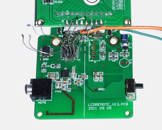
If you want to take a photograph with a professional look, proper lighting is going to be critical. [Richard] has been using a commercial lighting solution in his studio. His Lencarta UltraPro 300 studio strobes provide adequate lighting and also have the ability to have various settings adjusted remotely. A single remote can control different lights setting each to its own parameters. [Richard] likes to automate as much as possible in his studio, so he thought that maybe he would be able to reverse engineer the remote control so he can more easily control his lighting.

[Richard] started by opening up the remote and taking a look at the radio circuitry. He discovered the circuit uses a nRF24L01+ chip. He had previously picked up a couple of these on eBay, so his first thought was to just promiscuously snoop on the communications over the air. Unfortunately the chips can only listen in on up to six addresses at a time, and with a 40-bit address, this approach may have taken a while.

Not one to give up easily, [Richard] chose a new method of attack. First, he knew that the radio chip communicates to a master microcontroller via SPI. Second, he knew that the radio chip had no built-in memory. Therefore, the microcontroller must save the address in its own memory and then send it to the radio chip via the SPI bus. [Richard] figured if he could snoop on the SPI bus, he could find the address of the remote. With that information, he would be able to build another radio circuit to listen in over the air.

Using an Open Logic Sniffer, [Richard] was able to capture some of the SPI communications. Then, using the datasheet as a reference, he was able to isolate the communications that stored information int the radio chip’s address register. This same technique was used to decipher the radio channel. There was a bit more trial and error involved, as [Richard] later discovered that there were a few other important registers. He also discovered that the remote changed the address when actually transmitting data, so he had to update his receiver code to reflect this.

The receiver was built using another nRF24L01+ chip and an Arduino. Once the address and other registers were configured properly, [Richard's] custom radio was able to pick up the radio commands being sent from the lighting remote. All [Richard] had to do at this point was press each button and record the communications data which resulted. The Arduino code for the receiver is available on the project page.

[Richard] took it an extra step and wrote his own library to talk to the flashes. He has made his library available on github for anyone who is interested.


Filed under: Arduino Hacks, radio hacks