Posts with «light» label

Jigsaw Puzzle Lights Up With Each Piece

Putting the last piece of a project together and finally finishing it up is a satisfying feeling. When the last piece of a puzzle like that is a literal puzzle, though, it’s even better. [Nadieh] has been working on this jigsaw puzzle that displays a fireworks-like effect whenever a piece is placed correctly, using a lot of familiar electronics and some unique, well-polished design.

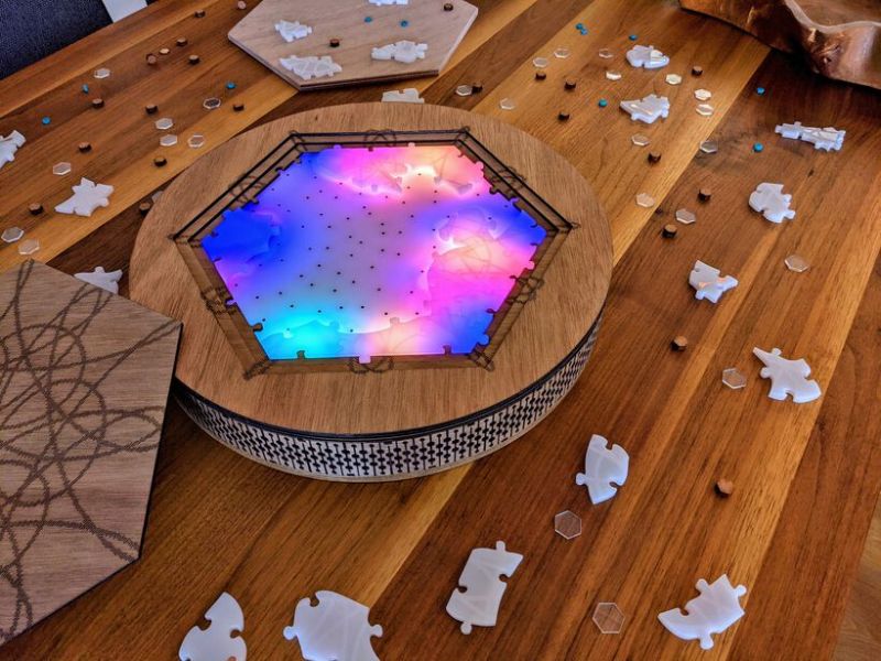
The puzzle is a hexagonal shape and based on a hexagonally symmetric spirograph, with the puzzle board placed into an enclosure which houses all of the electronics. Each puzzle piece has a piece of copper embedded in a unique location so when it is placed on the board, the device can tell if it was placed properly or not. If it was, an array of color LEDs mounted beneath a translucent diffuser creates a lighting effect that branches across the entire board like an explosion. The large number of pieces requires a multiplexer for the microcontroller, an ATtiny3216.

This project came out of a FabAcademy, so the documentation is incredibly thorough. In fact, everything on this project is open sourced and available on the project page from the code to the files required for cutting out the puzzle pieces and the enclosure. It’s an impressive build with a polish we would expect from a commercial product, and reminds us of an electrified jigsaw puzzle we saw in a previous build.

Thanks to [henk] for the tip!

Dinural Reef Control Realistically Insolates Your Aquarium

[Phillip]’s project is not just great for learning new words, it also shows just how complex natural systems can be. 

As we know from news around the word, reefs are delicate systems prone to damage from just about any imaginable threat. Escaped aquarium fish, sunscreen, and the wayward feet of well meaning tourists to name a few. So it’s no wonder that aquarium hobbyists sometimes go to incredible lengths to simulate the natural environments these creatures live in.

While [Phillip] is still tinkering with his designs for this project, we found the data he included really interesting. His goal is to be able to plug in any coordinate on the earth and have the lights replicate the location. That includes not just the sun, but also the light from the moon as many corals seem to only spawn during certain tides. Of course no LED is perfect so he’s even experimenting with putting light sensors under the water to provide a feedback loop to make it perfect.

We really like the ambition of this project and we hope he continues.

Hack a Day 04 Jan 06:00
arduino  coral  led  led hacks  light  reef  simulate  tide  

Super simple controller for Motorcycle LED lights

For automobiles, especially motorcycles, auxiliary lighting that augments the headlights can be quite useful, particularly when you need to drive/ride through foggy conditions and poorly lit or unlit roads and dirt tracks. Most primary lighting on vehicles still relies on tungsten filament lamps which have very poor efficiency. The availability of cheap, high-efficiency LED modules helps add additional lighting to the vehicle without adding a lot of burden on the electrical supply. If you want to add brightness control, you need to either buy a dimmer module, or roll your own. [PatH] from WhiskeyTangoHotel choose the latter route, and built a super simple LED controller for his KLR650 bike.

He chose a commonly available 18 W light bar module containing six 3 W LEDs. He then decided to build a microcontroller based dimmer to offer 33%, 50% and 100% intensities. And since more code wasn’t going to cost him anything extra, he added breathing and strobe modes. The hardware is as barebones as possible, consisting of an Arduino Nano, linear regulator, power MOSFET and control switch, with a few discretes thrown in. The handlebar mounted control switch is a generic motorcycle accessory that has two push buttons (horn, headlight) and a slide switch (turn indicators). One cycles through the various brightness modes on the pushbutton, while the slide switch activates the Strobe function. A status indicator LED is wired up to the Nano and installed on the handlebar control switch. It provides coded flashes to indicate the selected mode.

It’s a pity that the “breathing” effect is covered under a patent, at least for the next couple of years, so be careful if you plan to use that mode while on the road. And the Strobe mode — please don’t use it — like, Ever. It’s possible to induce a seizure which won’t be nice for everyone involved. Unless you are in a dire emergency and need to attract someone’s attention for help.


Filed under: led hacks
Hack a Day 09 Sep 09:00

WALTER - The Arduino Photovore Insect Robot

Primary image

What does it do?

Navigate around and seeking light

[Please excuse my English]

Cost to build

Embedded video

Finished project

Complete

Number

Time to build

Type

URL to more information

Weight

read more

WALTER - The Arduino Photovore Insect Robot

Primary image

What does it do?

Navigate around and seeking light

[Please excuse my English]

Cost to build

Embedded video

Finished project

Complete

Number

Time to build

Type

URL to more information

Weight

read more

WALTER - The Arduino Photovore Insect Robot

Primary image

What does it do?

Navigate around and seeking light

[Please excuse my English]

Cost to build

Embedded video

Finished project

Complete

Number

Time to build

Type

URL to more information

Weight

read more

WALTER - The Arduino Photovore Insect Robot

Primary image

What does it do?

Navigate around and seeking light

[Please excuse my English]

Cost to build

Embedded video

Finished project

Complete

Number

Time to build

Type

URL to more information

Weight

read more

Minecraft Sword Lights Up When Nearby Friends

With All Hallow’s Eve looming close, makers have the potential to create some amazing costumes we’ll remember for the rest of the year. If you’re a fan of the hugely addict-*cough* popular game Minecraft, perhaps you’ve considered cosplaying as your favorite character skin, but lacked the appropriate props. [Graham Kitteridge] and his friends have decided to pay homage to the game by making their own light-up Minecraft swords.

These swords use 3D-printed and laser-cut parts, designed so as to hide the electronics for the lights and range finder in the hilt. Range finder? Oh, yes, the sword uses an Arduino Uno-based board to support NewPixels LEDs and a 433Mhz radio transmitter and receiver for ranged detection of other nearby swords that — when they are detected — will trigger the sword to glow. Kind of like the sword Sting, but for friendlies.

All of the files for the parts are available on the project’s Thingverse page and the board setup can be purchased here. If you want to have some fun controlling the real world from inside Minecraft, check out how this fan uses it to turn on lamps in their home.


Filed under: 3d Printer hacks, Arduino Hacks, weapons hacks

Arduino Disco Ball Cake


Description

This is a fun project that will surely impress anyone you make this for. If you are having a "Disco" themed party, you cannot have a boring old cake. Let me tell you, this is probably the only Arduino project that my wife has ever been willing to be a part of. She did the hard work of putting the cake together, and I, well.... I was in charge of lighting. My biggest fear was that one of the wires would come loose and ruin the event at the most critical moment... While a wire did come loose, I managed to fix it in time before the guests arrived. Ok enough of my monologue, let me show you how to make one of these things.


Parts Required:

Note: powering this project using batteries is possible, but not recommended, and done at your own risk.

You will also need a Disco Ball Cake which you will have to make(or buy).My wife made this one. And as you will see shortly, the cake on the inside was Pink, because it was a strawberry cake.


Arduino Libraries and IDE

You can get the Arduino IDE from here: https://www.arduino.cc/en/Main/Software
I used version 1.6.4, which is probably way out of date... but works fine nonetheless.
 
You can get information about how to use the FastLED library here: http://fastled.io/
And you can download it from here: FastLED Library
I used version 3.0.3, which is also probably out of date.

ARDUINO CODE:

ARDUINO CODE DESCRIPTION:

  • FastLED Library: You need to make sure that you have downloaded and installed the FastLED library into your Arduino IDE. The library is included in this sketch otherwise the FastLED functions will not work.
  • The "NUM_LEDS" variable: tells the Arduino how many LEDS are in use. In this case, we have 4 LED rings, with each LED ring containing 16 LEDs, and therefore a total of 64 LEDs. If you define a lower number, for example 16, then the sketch would only illuminate the LEDs on the first LED ring.
  • The "DATA_PIN" variable: tells the Arduino which Digital Pin to use for data transmission to the LED ring. In this case, I am using Digital Pin 9.
  • Other variables: I have a couple of other variables which are used for LED randomisation and hue control. Hue is the colour of the LED. By incrementing the hue variable, you can get the LEDs to cycle in a rainbow-like pattern. The "hue" variable is a "byte", which means that it will only go up to a maximum value of 255, before it jumps back down to zero.
  • Initialisation Code: If you have a different LED ring to the one in this tutorial, you may have to modify the initialisation code. This LED ring has a WS2812-B chipset (according to the ICStation website), and so this line:
     
    FastLED.addLeds(leds, NUM_LEDS); Will tell the FastLED library which chipset is being used (NEOPIXEL), the pin used for data transmission (DATA_PIN), the LED array to be controlled (leds), and the number of LEDs to be controlled (NUM_LEDS).
  • In the "loop()": section of the code: the "hue" variable is incremented to create a rainbow effect, and a random LED is selected using the FastLED's random8() function.
  • The random8(x) function: will randomly choose a number from 0 to x.
  • The randomSeed() function: is there to help "truely randomise" the number. This is helped by reading the randomness of a floating analogPin (A0). It doesn't have to be analogPin 0, it can be any unused analog pin.
  • leds[rnd].setHSV(hue,255,255): This line sets the random LED to have a hue equal to the "hue" variable, saturation equal to 255, and brightness equal to 255. Saturation equal to zero will make the LED shine white.
    Brightness of zero essentially turns the LED OFF.
  • FastLED.show(): No physical changes will be made to the LED ring display until a message is sent from the Arduino to the Digital input pin of the LED ring. This message is transmitted when you call the FastLED.show(); function. This tells the LED rings to update their display with the information contained within the led array (leds). So if you set all LEDs to turn on, the board will not illuminate the LEDs until the FastLED.show(); function is called. This is important to know - especially when trying to design your own LED sequences.
  • The delay(50) line: will set the amount of time between flashes to 50 milliseconds. You can change the delay to increase or decrease the number of flashes per second.
  • The leds[i].fadeToBlackBy( 180 ) function: essentially fades the LEDS by 180 units. You can increase or decrease this number to achieve the desired fade speed. Be warned however, that if you forget to call this function or if you fail to fade the LEDs sufficiently, then you may end up with ALL LEDs turning on, which could potentially destroy your Arduino board - i.e. depending on the number of LED rings you have, and how you have chosen to power them.


The Cake


  • Slide 1 - Base Plate: It is important to create the base plate with all of the electronics fitted and in working order BEFORE you put the Cake onto it. Trying to fit wires/cables LEDs and circuits under the base plate while there is a Cake ontop is a recipe for disaster. So prepare the base plate first, and then move to the cake making part later.
  • Slide 2 - Bake Cake: You will need a couple of hemisphere cake pans to make the two sides of the ball. You have to make a relatively dense cake to withstand the overall weight of the cake, icing and fondant, and to maintain it's shape. Once cooled and chilled, you can place them ontop of each other to form a sphere. They are held together by a layer of icing between them.
  • Slide 3 - Fondant Icing: The fondant icing has to be rolled out on a special non-stick mat. We found that adding a bit of flour helped to reduce the stickiness. There are special rollers which ensure that the thickness of the fondant is consistent throughout. You then have to cut them into square pieces (about 1 cm squares worked well for us). The squares are then painted Silver with a special/edible silver fondant glaze. You may need to use a few coats, and allowing it to dry between coats.
  • Slide 4 - Iced Cake on Base: The cake can either be iced on or off the base plate... probably better to do it off the base plate. But if you decide to do it on the base plate, you will need to protect the LEDs from stray icing that may fall from the cake (in the process). Once the cake has been fully iced (with icing/frosting), you will need to place the cake into the central position on the board. There may be a chance that the cake may slide from the base... so do what you need to do to make it stay put.
  • Slides 5-7 - Place Fondant Squares: While the icing is still soft, you will then need to quickly, methodically and tirelessly place the fondant squares in a horizontal linear pattern around the cake. Work your way towards the north and south poles of the cake doing one row at a time. You can cut a fondant circle for the north pole of the cake. In slide 7, you will see a hole at the top of the cake. This was made to cold a plastic canister inside, which would be used later the hold the decorations in place at the top of the cake. Do this before placing the fondant circle at the top of the cake.
  • Slide 8 - Add Glitter: After placing all of the fondant squares onto the cake, it is very possible that some of the Silver glaze may have been wiped off some of the squares. This is where you go over it again with a few more coats of silver glaze, and on the last coat, before it dries, you can sprinkle some edible glitter all around the cake to give it that extra shine.
  • Slide 9 - The end product: The final step is to add some wire sparklers and some other decorations to the top of the cake. Push the wires through the fondant cap at the north pole into the canister within. This will hold the wires in place without ruining all of your hard work.


LED Ring pins

  • WS2812-B chipset: This LED ring uses the WS2812-B chipset, and has 4 break-out pins
    (GND, 5V, Din, Dout)
  • Power: To power this module, you need to provide 5V and up to 1A of current
  • Signals: To control the LED ring, you need to send signals to it via the Digital Input pin (Din).
    You can connect another LED ring to this one by utilising the Digital Output pin (Dout)


Power Usage Guide

  • General Rule: Each individual LED on the ring can transmit Red, Green and Blue light.The combinations of these colours can make up any other colour. White light is made up of all three of these colours at the same time. Each individual colour will draw approximately 20mA of current when showing that colour at maximum brightness. When shining white at maximum brightness, the single LED will draw approximately 60mA.
  • Power multiplier: If each LED can draw up to 60mA and there are 16 LEDs on a single LED ring, then 16x60mA = 960mA per LED ring. To be safe, and to make the maths easier, you need to make sure that you provide enough current to accommodate 1A per LED ring. So 4 LED rings will need a 5V 4A power supply if you want to get full functionality out of the modules.


Fritzing diagram

Connecting ONE LED Ring to the Arduino- (Click to enlarge)


  • 3 wires: You only need 3 wires to connect to the LED ring. If you only plan to light up a couple of LEDs at any one time this should be ok.
  • The SAFE WAY: A safer way to do this is to use an external power supply to power both the Arduino and the LED ring.
  • Electrolytic capacitor: By connecting a large 4700 uF 16V Electrolytic capacitor between the positive and negative terminals of power supply leads, with the negative leg of the capacitor attached to the negative terminal of the power supply, you will protect your LED rings from any initial onrush of current.


  • Protecting Resistor: It is also advisable to place a 300-400 ohm resistor between the Arduino's Digital Pin 9 (D9) and the LED Ring's Digital Input pin (Din). This protects the first LED from potential voltage spikes
  • Suitable wires: If you plan to chain a few of these LED rings together (see below), then you will probably want to keep the wires as short as possible and use a decent guage wire that can handle the current being drawn through them.


Connecting TWO LED Rings to the Arduino- (Click to enlarge)


  • Three extra wires:You only need 3 extra wires to connect an additional LED ring. A wire needs to connect the Digital output (Dout) of the first LED ring to the Digital Input (Din) of the 2nd LED ring.
  • Stay safe: Once again, a safer way to do this is to use an external power supply, a large electrolytic capacitor at the terminals, and a 300-400 ohm resistor between the Arduino and the first LED ring's digital input pin.


Connecting FOUR LED Ring to the Arduino- (Click to enlarge)


  • Sixty Four LEDs:You need 3 extra wires for each additional LED ring. 4 LED rings provides a total of 64 LEDs.
  • Watch the AMPS:At full brightness, this setup could potentially draw up to 4amps (or roughly 1 amp per LED ring)
  • External Supply essential: It is essential to use an external power supply to power these LEDs when there are so many of them. If you don't use an external power supply and you accidentally illuminate ALL of the LEDs, then you are likely to damage the microcontroller from excessive current draw.


Connection Tables

How to connect ONE LED Ring to the Arduino- (Click to enlarge)


How to connect TWO LED Rings to the Arduino- (Click to enlarge)


Concluding comments

In this tutorial I showed you how to go about decorating a Disco Ball cake and also showed you how to use the RGB LED rings from ICStation. If you look at the video you will see just how versatile these LED rings are. I would like to thank my wife for providing such an exciting project to work on, and ICStation for their collaborative efforts. Please make sure to share this project with all of your friends and family.


If you like this page, please do me a favour and show your appreciation :

 
Visit my ArduinoBasics Google + page.
Follow me on Twitter by looking for ScottC @ArduinoBasics.
I can also be found on Pinterest and Instagram.
Have a look at my videos on my YouTube channel.


ScottC 04 Jun 07:38