Posts with «motorcycle» label

Adding Upgrades To A Stock Motorcycle

In today’s world of over-the-air firmware upgrades in everything from cars to phones to refrigerators, it’s common for manufacturers of various things to lock out features in software and force you to pay for the upgrades. Even if the hardware is the same across all the models, you can still be on the hook if you want to unlock anything extra. And, it seems as though Suzuki might be following this trend as well, as [Sebastian] found out when he opened up his 2011 Vstrom motorcycle.

The main feature that was lacking on this bike was a gear indicator. Even though all the hardware was available in the gearbox, and the ECU was able to know the current gear in use, there was no indicator on the gauge cluster. By using an Arduino paired with an OBD reading tool (even motorcycles make use of OBD these days), [Sebastian] was able to wire an LED ring into the gauge cluster to show the current gear while he’s riding.

The build is very professionally done and is so well blended into the gauge cluster that even we had a hard time spotting it at first. While this feature might require some additional lighting on the gauge cluster for Suzuki to be able to offer this feature, we have seen other “missing” features in devices that could be unlocked with a laughably small amount of effort.

Super simple controller for Motorcycle LED lights

For automobiles, especially motorcycles, auxiliary lighting that augments the headlights can be quite useful, particularly when you need to drive/ride through foggy conditions and poorly lit or unlit roads and dirt tracks. Most primary lighting on vehicles still relies on tungsten filament lamps which have very poor efficiency. The availability of cheap, high-efficiency LED modules helps add additional lighting to the vehicle without adding a lot of burden on the electrical supply. If you want to add brightness control, you need to either buy a dimmer module, or roll your own. [PatH] from WhiskeyTangoHotel choose the latter route, and built a super simple LED controller for his KLR650 bike.

He chose a commonly available 18 W light bar module containing six 3 W LEDs. He then decided to build a microcontroller based dimmer to offer 33%, 50% and 100% intensities. And since more code wasn’t going to cost him anything extra, he added breathing and strobe modes. The hardware is as barebones as possible, consisting of an Arduino Nano, linear regulator, power MOSFET and control switch, with a few discretes thrown in. The handlebar mounted control switch is a generic motorcycle accessory that has two push buttons (horn, headlight) and a slide switch (turn indicators). One cycles through the various brightness modes on the pushbutton, while the slide switch activates the Strobe function. A status indicator LED is wired up to the Nano and installed on the handlebar control switch. It provides coded flashes to indicate the selected mode.

It’s a pity that the “breathing” effect is covered under a patent, at least for the next couple of years, so be careful if you plan to use that mode while on the road. And the Strobe mode — please don’t use it — like, Ever. It’s possible to induce a seizure which won’t be nice for everyone involved. Unless you are in a dire emergency and need to attract someone’s attention for help.


Filed under: led hacks
Hack a Day 09 Sep 09:00

Testing riders’ clothing with Arduino

Worse for Wear is a clothing company  for women who ride motorcycles. The fascinating clothing they produce is very fashionable, comfortable, and needs to protect riders from impact and abrasion if they have an accident. Jackets and trousers have knee and hip pads  included to protect the rider when sliding many meters across asphalt. That’s why the fabric must be strong and abrasion resistant because if the fabric wears away too quickly, the rider’s skin will be exposed and injured.

To choose the perfect fabric, Scott and Laura, co-founders of the company, created an Impact Abrasion Resistance Testing Machine running on Arduino Uno to perform tests on different materials like knit fabrics, woven fabrics, and leather, to see how long it takes before the material is sanded completely through. I interviewed them to learn more about it!

- What is the impact abrasion resistance testing machine and how does it work?

When selecting fabric to use in our clothes, we have to make sure that it is strong and abrasion resistant. We use the impact abrasion resistance test machine to determine which fabrics will withstand abrasion (scraping and sliding) the best. It is important to us to test the fabrics ourselves and not rely solely on the claims of fabric manufacturers.

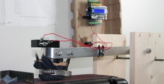
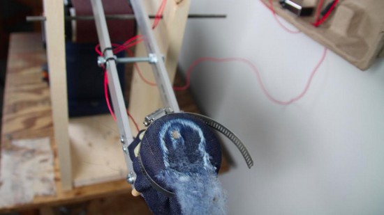
The machine has a weighted arm, like a hammer, suspended above an abrasive belt sander. A sample of the fabric that we want to test is wrapped around the head of the hammer and then dropped onto the moving sanding belt. An Arduino Uno is used to record the amount of time it takes to sand through the fabric sample.

Check the video below to see how it works:

- Why did you decide to use Arduino?

We have used Lilypad Arduino and Arduino Uno before to prototype some e-textile projects, so it was easy for us to get started on this one with our previous experience. The large number of accessory boards available made it simple to add an informational display and user interface to the machine. In just a few hours, we were able to very quickly create a machine to compare the abrasion resistance of a variety of fabric samples. The simplicity of working with Arduino was a very good choice for us, because our real business is creating clothing, not building test machines!

- What does Arduino control in the machine? 

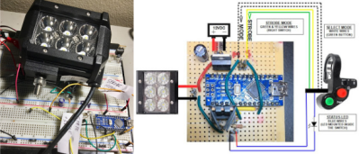
An Arduino Uno is used to record the amount of time it takes to sand through the fabric sample. The method we use is based on European Union standards for motorcycle safety gear testing. To measure the fabric’s abrasion time, we use two thin copper wires (magnet wire). One wire is placed inside and another outside of the fabric sample before everything is wrapped around the head of the hammer. Each wire is then connected to ground on one end and an to input pin on the Arduino on the other end. The pins are in INPUT_PULLUP mode so a current runs through them. The LCD display on the Arduino tells us when both wires are connected properly.

Then, we start the belt sander and drop the hammer onto the spinning sanding belt. The outer wire breaks very quickly, breaking the connection to that pin [ digitalRead(outerWireIn) == HIGH ]. At this point, the Arduino records the start time. When the fabric wears through – usually within a couple of seconds – the inner wire is exposed to the sanding belt and quickly breaks. That marks the end time, which the Arduino records and displays on the LCD shield. A single type of fabric must be tested at least five times in order to make sure our recorded times are accurate.

Explore the details and download the code on Worse for Wear blog.

Motorcycle Gyromount Always Delivers Perfect Video

If you’ve ever watched MotoGP (motorcycle) racing, you might have wondered how the camera appears to stay level even while the bike turns left and right, nearly becoming horizontal. Saftari was curious about this himself and, rather than simply answering the question, he built a gyroscopic camera rig that allows the camera […]

Read more on MAKE

The post Motorcycle Gyromount Always Delivers Perfect Video appeared first on Make:.

Helmet of many LEDs built for Burning Man

This motorcycle helmet was heavily altered to accept all of the hardware that goes into driving that huge array of LEDs. [Brian Cardellini] built it to wear at burning man. He claims to have been in over his head with the project, but we certainly don’t get that feeling when we see the thing in action. It’s light on build details, but there are plenty of demo shots in the video after the break. The animation and fading action really gets started about a minute and a half into it.

One of the early frames of the video is a shot of the parts order webpage. Since it’s an HD clip we were able to glean a few bits and pieces from that. It includes a MAX7219 LED Display Driver and fifteen 25-packs of Blue LEDs. Now that chip is a great choice, and one of the later shots shows two of them on breakout board driven by an Arduino. The look is very clean since he carved out most of the helmet’s padding to make room for the electronics.

[via Adafruit]


Filed under: led hacks, wearable hacks