Posts with «microcontrollers» label

CH32 RISC-V MCUs Get Official Arduino Support

Like many of you, we’ve been keeping a close eye on the CH32 family of RISC-V microcontrollers from WCH Electronics. You can get the CH32V003, featuring 2 kB RAM and 16 kB of flash for under fifteen cents, and the higher-end models include impressive features like onboard Ethernet. But while the hardware is definitely interesting, the software side of things has been a little rocky compared to what we’ve come to expect from modern MCUs.

Things should start looking up a bit though with the release of an Arduino core for the CH32 direct from WCH themselves. It’s been tested on Windows, Linux, and Mac, and supports the CH32V00x, CH32V10x, CH32V20x, CH32V30x, and CH32X035 chips. Getting it installed is as easy as adding the URL to the Arduino IDE’s Boards Manager interface, though as the video below shows, running it on Linux does require an extra step or two.

So far, we’ve seen several projects, like this temperature sensor or this holiday gizmo that use [cnlohr]’s open-source toolchain. But there’s no question that plenty of hobbyists out there feel more comfortable in the Arduino environment, and if those folks are now able to pick up a CH32 and do something cool, that means more people jumping on board, more libraries developed, more demo code written…you get the idea.

Just like the ESP8266’s popularity exploded when it was added to the Arduino IDE, we’ve got high hopes for the CH32 family in the coming months.

Arduino Measures Remaining Battery Power With Zero Components, No I/O Pin

[Trent M. Wyatt]’s CPUVolt library provides a fast way to measure voltage using no external components, and no I/O pin. It only applies to certain microcontrollers, but he provides example Arduino code showing how handy this can be for battery-powered projects.

The usual way to measure VCC is simple, but has shortcomings.

The classical way to measure a system’s voltage is to connect one of your MCU’s ADC pins to a voltage divider made from a couple resistors. A simple calculation yields a reading of the system’s voltage, but this approach has two disadvantages: one is that it constantly consumes power, and the other is that it ties up a pin that you might want to use for something else.

There are ways to mitigate these issues, but it would be best to avoid them entirely. Microchip application note 2447 describes a method of doing exactly that, and that’s precisely what [Trent]’s Arduino library implements.

What happens in this method is one selects Vbg (a fixed internal voltage reference that is temperature-independent) as Vin, and selects Vcc as the ADC’s voltage reference. This is essentially backwards from how the ADC is normally used, but it requires no external hookup and is only a bit of calculation away from determining Vcc in millivolts. There is some non-linearity in the results, but for the purposes of measuring battery power in a system or deciding when to send a “low battery” signal, it’s an attractive solution.

Being an Arduino library, CPUVolt makes this idea very easy to use, but the concept and method is actually something we have seen before. If you’re interested in the low-level details, then check out our earlier coverage which goes into some detail on exactly what is going on, using an ATtiny84.

This 3D Printable Soldering Air Filter Really Sucks

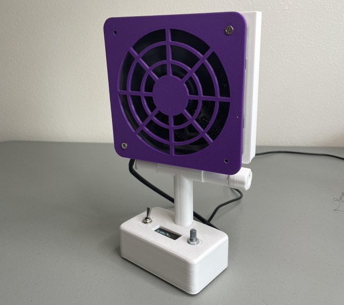
If you solder (and we know you do), you absolutely need ventilation, even for that lead-free stuff. Fortunately, [tinyboatproductions] has gotten into air quality lately and is here to help you with their snappy 3D printed air-filtering design.

At the heart of this build is a 120 mm notoriously-quiet Noctua fan coupled with a carbon filter. It does what you’d think — position the fan the right way and it sucks the air through the filter, which catches all those nasty particles.

The only problem is that the Noctua uses PWM, so there’s no governing it with a just potentiometer. To get around this, [tinyboatproductions] introduced an Arduino Nano and a buck converter, both of which were admittedly a bit overkill. Now the speed can be controlled with a pot.

Once control of the fan was sorted, [tinyboatproductions] decide to add an OLED display to show the fan speed and power condition, which is a nice touch. Be sure to check out the build video after the break.

If this doesn’t have quite enough features for you, here’s one that’s battery powered.

This Arduino Debugger Uses the CH552

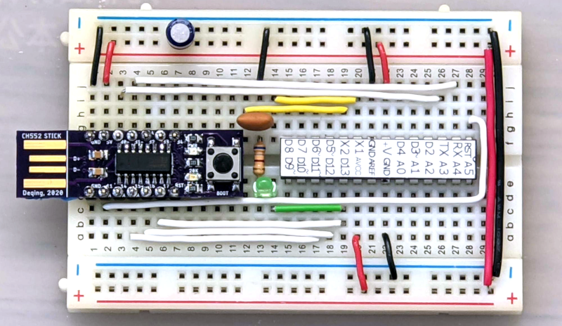
One of the things missing from the “classic” Arduino experience is debugging. That’s a shame, too, because the chips used have that capability. However, the latest IDE has the ability to work with external debuggers and if you want to get started with a classic ATMega Arduino, [deqing] shows you how to get started with a cheap CH552 8-bit USB microcontroller board as the debugging dongle.

The CH552 board in question is a good choice, primarily because it is dirt cheap. There are design files on GitHub (and the firmware), but you could probably pull the same trick with any of the available CH552 breakout boards.

There was a time when having a god-eye view of your embedded system required an expensive in-circuit emulation system. These were expensive, difficult to deploy, and rare. Then, CPUs started adding debugging hardware right on the chip. A few spare pins on the CPU and some sort of adapter would give you most of what you wanted from an emulation system. Although these adapters are often proprietary, sometimes they aren’t, or they have been reverse-engineered. If you know the protocol, it is easy enough to get a processor to speak it for you. That’s why you often see, for example, Raspberry Pi Picos debugging other Picos. There’s nothing you can’t do a million other ways here, but it is an excellent step-by-step tutorial for getting started without breaking the bank.

RP2040 DMA Hack Makes Another ‘CPU Core’

[Bruce Land] of Cornell University will be a familiar name to many Hackaday readers, searching the site for ‘ECE4760′ will bring up many interesting topics around embedded programming. Every year [Bruce] releases yet more of the students’ work out into the wild to our great delight. This RP2040-based project is a bit more abstract than some previous work and shows yet another implementation of an older hack to utilise the DMA hardware of the RP2040 as another CPU core. While the primary focus of the RP2040 DMA subsystem is moving data between memory spaces, with minimal CPU intervention, the DMA control blocks have some fairly complex behaviour. This allows for a Turing-complete CPU to be implemented purely with the DMA hardware and a sprinkling of memory.

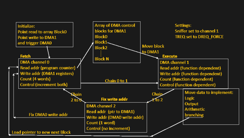
The method ties up three of the twelve DMA channels, and is estimated to have a similar performance to ‘an Arduino’ but [Bruce] doesn’t specify which one of the varied models that could be. But who cares anyway? Programming the CPU is a matter of leveraging the behaviour of the hardware, which is all memory mapped and targetable by the DMA. For example, the CPU can waggle GPIO pins by using the DMA to write values to the peripheral address space. The basic flow can be seen in the image above. DMA0 is used as the program counter, which points DMA1 to an array of DMA control blocks, a sequence of which codes for some of the ‘opcodes’ of the CPU model. DMA0 chains to (hands over control to) DMA1 which reads the control blocks and configures itself accordingly. DMA1 performs whatever data move is programmed, chains to DMA2, which in turn reprograms the DMA0 program counter to point to the next block in the list to be executed by DMA1.

By also using DMA1 to modify subsequent DMA1 control blocks (that’s self-modifying code happening there!) the system can implement more useful operations such as addition, logical operations, and conditional branching. Transport-triggered operations in certain shadow registers enable atomic set, reset, and XOR operations. All clever stuff, and a wonderful student project to have been involved with. [Bruce] points out a paper (using the Pi2) from the WOOT 2015 workshop which might offer a better explanation of this whole process.

If you’re still wondering who [Bruce Land] is and want a bit of a primer on some of these topics, then check out our previous coverage. If this theoretical stuff is a bit heavy (i.e. boring) then some of the projects have a more practical bent, such as the critical task of colour-sorting skittles.

Thumbnail image: Thomas Glau, CC BY-SA 4.0.

Hack a Day 21 Jan 03:00

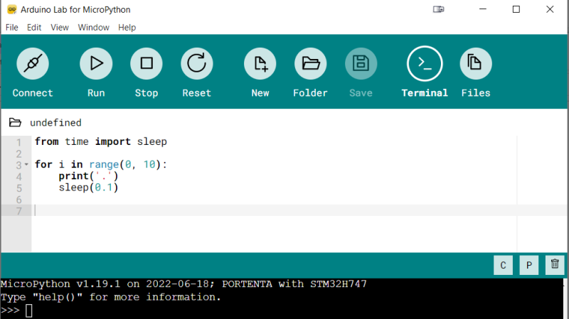
Arduino Brings A MicroPython IDE

Both Arduino and MicroPython are giants when it comes to the electronics education area, and each one of them represents something you can’t pass up on as an educator. Arduino offers you a broad ecosystem of cheap hardware with a beginner-friendly IDE, helped by forum posts explaining every single problem that you could and will stumble upon. MicroPython, on the other hand, offers a powerful programming environment ripe for experimentation, and doesn’t unleash a machine gun fire of triangle brackets if you try to parse JSON slightly incorrectly. They look like a match made in heaven, and today, from heaven descends the Arduino Lab for MicroPython.

This is not an Arduino IDE extension – it’s a separate Arduino IDE-shaped app that does MicroPython editing and uploads code to your board from a friendly environment. It works over a serial port, and as such, the venerable ESP8266-based boards shouldn’t be be left out – it even offers file manager capabilities! Arduino states that this is an experimental effort – it doesn’t yet have syntax checks, for instance, and no promises are made. That said, it already is a wonderful MicroPython IDE for beginner purposes, and absolutely a move in the right direction. Want to try? Download it here, there’s even a Linux build!

High-level languages let you build projects faster – perfect fit for someone getting into microcontrollers. Hopefully, what follows is a MicroPython library manager and repository! We’ve first tried out MicroPython in 2016, and it’s come a long way since then – we’ve seen quite a few beginner-friendly MicroPython intros, from a gaming handheld programming course, to a bipedal robot programming MicroPython exploration. And, of course, you can bring your C libraries with you.

Trigger Your Home Automation Routines With Home Buttons

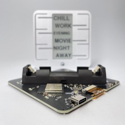
Home automation systems are all well and good, so long as the person who built it all is around to drive it. Let’s face it, they’re quite often a complex web of interconnected systems, all tied to the specifics of one’s home — and someone less familiar with it all could get a little irritated if, on a chilly day, the interface to the boiler is via a Python script, and something won’t work. Just saying. Home Buttons by [Matej Planinšek] over on Hackaday.IO is a nicely polished project, which aims to take some of the hackiness out of such automation by providing a sleek front end to those automation routines, enabling anyone to rock on over and set one in action without hassle.

The PCB is based around the ESP32-S2-mini which deals with WiFi connectivity and integration with Home Assistant using the usual MQTT protocol. We expect integration with other flavors of home automation would not be difficult to achieve. The center of the unit holds a simple E-Ink display, for that low-standby power. Specifically, the unit chosen is a Good Display GDEY029T94 2.9″ which this scribe can confirm is easy to interface and pretty cheap to purchase from the usual Chinese online vendors. This was matched up with six clicky Alps SKRB-series low-profile tact switches, which sit on either side of the display, and corresponds to a flexure-type affair on the 3D printed front casing. Neat and simple.

The PCB design was provided in Altium format, which you can find on the project GitHub page. This shows a straightforward design, with a few nice little details here and there. The internally mounted 186550 cell is reportedly good for at least a year of operation, but when time, it can be charged via USB. A Xysemi XB8608AF (PDF) protection chip provides appropriate limiting for the 186550 cell, shielding it from the perils of overcharging, discharging, and whatnot. Not that that is likely in this current setup. A Sensiron SHTC3 humidity and temperature sensor is also in there, hanging off the I2C bus, which makes sense for this application.

Home Automation hacks are plenty on these pages, like this scroll-wheel interface, for instance. If all this stuff is looking quite overbearingly complicated to get into, how about starting with a Pico W?

Plumbing Valves as Heavy Duty Analog Inputs

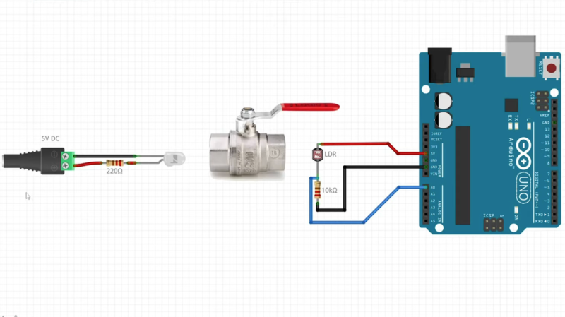
Input devices that can handle rough and tumble environments aren’t nearly as varied as their more fragile siblings. [Alastair Aitchison] has devised a brilliant way of detecting inputs from plumbing valves that opens up another option. (YouTube) [via Arduino Blog]

While [Aitchison] could’ve run the plumbing valves with water inside and detected flow, he decided the more elegant solution would be to use photosensors and an LED to simplify the system. This avoids the added cost of a pump and flow sensors as well as the questionable proposition of mixing electronics and water. By analyzing the change in light intensity as the valve closes or opens, you can take input for a range of values or set a threshold for an on/off condition.

[Aitchison] designed these for an escape room, but we can see them being great for museums, amusement parks, or even for (train) simulators. He says one of the main reasons he picked plumbing valves was for their aesthetics. Industrial switches and arcade buttons have their place, but certainly aren’t the best fit in some situations, especially if you’re going for a period feel. Plus, since the sensor itself doesn’t have any moving parts, these analog inputs will be easy to repair should anything happen to the valve itself.

If you’re looking for more unusual inputs, check out the winners of our Odd Inputs and Peculiar Peripherals contest or this typewriter that runs Linux.

Tiny Thin Client is Small But Compatible

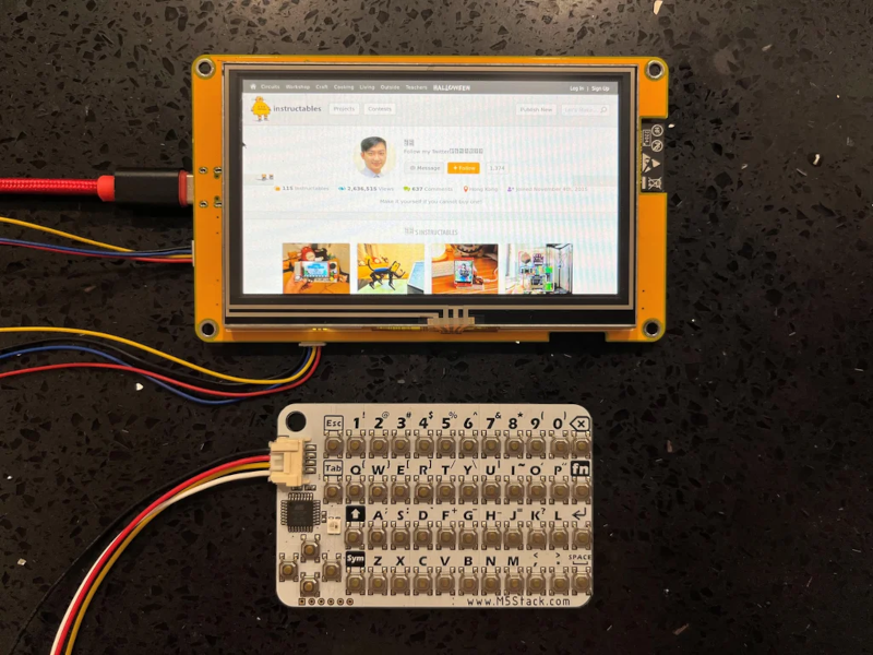
We were impressed with [moononournation’s] tiny thin client project. It claims to use an Arduino, but as you might guess it is using the Arduino software along with a network-enabled microcontroller like an ESP32. The impressive part is that it is standards-compliant and implements VNC’s RFB protocol.

The original coding for RFB on Arduino is from [Links2004] and armed with that, the thin client is probably easier to create than you would guess. However, this project wanted to use a larger screen and found that it led to certain problems. In particular, the original code had a 320×240 display. This project was to use an 800×480 display, but with the limits on the ESP32, the frame rate possible would be under 7 frames per second. The answer was to combine a 16-bit parallel interface with better compression back to the VNC server.

The little keyboard is probably not very practical, but it is compact. That would be another easy thing to modify. Currently, the keyboard uses I2C, but it would be straightforward to change things up. This would be a worthy base to build a bigger project on top. A 3D printed enclosure would be nice, too.

We’ve seen a number of projects built around commercial thin clients. Some from defunct businesses are good sources for obscure parts, too.

USB Power Isolator Keeps Smoke In

Anyone who’s done an electronics project knows the most important part of any good design is making sure to keep the magic smoke inside of all of the components. There are a lot of ways to make sure the smoke stays in there, but one of the most important is making sure that the power supply is isolated. If you’re using a USB port on a computer as your power source, though, it can be a little more complicated to isolate it from the computer.

The power supply is based around a small transformer with a set of diodes to act as a rectifier. Of course, while a transformer is great at isolating power supplies, it isn’t much good at DC. That’s what the ATtiny microcontroller is for. It handles the high-speed switching of the MOSFETs, which drive the transformer and handle some power regulation. There are two different power supplies created as part of this project as well — the first generates +5V much like a normal USB plug would have, and the other creates both +5V and -5V. It will be important not to mix these two up, or that tricky blue smoke may escape.

The project page goes into extensive details on the operation of the device, so if electrical theory is of interest, this will definitely be worth a read. Isolating a valuable computer from a prototype circuit is certainly important, but if you’re looking for a way to isolate a complete USB connection, look at this build which includes isolation for a USB to FTDI adapter.