Posts with «digital» label

Arduino Drum Platform Is Fast

Drums are an exciting instrument to learn to play, but often prohibitive if there are housemates or close neighbors involved. For that problem there are still electronic drums which can be played much more quietly, but then the problem becomes one of price. To solve at least part of that one, [Jeremy] turned to using an Arduino to build a drum module on his own, but he still had to solve yet a third problem: how to make the Arduino fast enough for the drums to sound natural.

Playing music in real life requires precise timing, so the choice of C++ as a language poses some problems as it’s not typically as fast as lower-level languages. It is much easier to work with though, and [Jeremy] explains this in great detail over a series of blog posts detailing his drum kit’s design. Some of the solutions to the software timing are made up for with the hardware on the specific Arduino he chose to use, including an even system, a speedy EEPROM, hardware timers, and an ADC that can sample at 150k samples per second.

With that being said, the hardware isn’t the only thing standing out on this build. [Jeremy] has released the source code on his GitHub page for those curious about the build, and is planning on releasing several more blog posts about the drum kit build in the near future as well. This isn’t the only path to electronic drums, though, as we’ve seen with this build which converts an analog drumset into a digital one.

Hack a Day 29 Jun 06:00

Building This Mechanical Digital Clock Took Balls

In the neverending quest for unique ways to display the time, hackers will try just about anything. We’ve seen it all, or at least we thought we had, and then up popped this purely mechanical digital clock that uses nothing but steel balls to display the time. And we absolutely love it!

Click to embiggen (you’ll be glad you did)

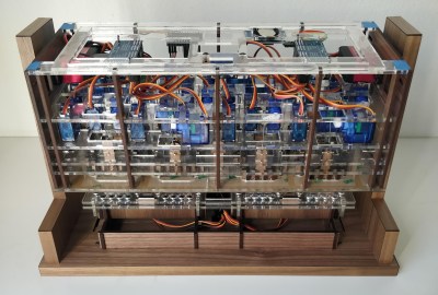
One glimpse at the still images or the brief video below shows you exactly how [Eric Nguyen] managed to pull this off. Each segment of the display is made up of four 0.25″ (6.35 mm) steel balls, picked up and held in place by magnets behind the plain wood face of the clock. But the electromechanical complexity needed to accomplish that is the impressive part of the build. Each segment requires two servos, for a whopping 28 units plus one for the colon. Add to that the two heavy-duty servos needed to tilt the head and the four needed to lift the tray holding the steel balls, and the level of complexity is way up there. And yet, [Eric] still managed to make the interior, which is packed with a laser-cut acrylic skeleton, neat and presentable, as well he might since watching the insides work is pretty satisfying.

We love the level of craftsmanship and creativity on this build, congratulations to [Eric] on making his first Arduino build so hard to top. We’ve seen other mechanical digital displays before, but this one is really a work of art.

Thanks to [Ruhan van der Berg] for the tip.

Follow the Bouncing Ball of Entropy

When [::vtol::] wants to generate random numbers he doesn’t simply type rand() into his Arduino IDE, no, he builds a piece of art. It all starts with a knob, presumably connected to a potentiometer, which sets a frequency. An Arduino UNO takes the reading and generates a tone for an upward-facing speaker. A tiny ball bounces on that speaker where it occasionally collides with a piezoelectric element. The intervals between collisions become our sufficiently random number.

The generated number travels up the Rube Goldberg-esque machine to an LCD mounted at the top where a word, corresponding to our generated number, is displayed. As long as the button is held, a tone will continue to sound and words will be generated so poetry pours forth.

If this take on beat poetry doesn’t suit you, the construction of the Ball-O-Bol has an aesthetic quality that’s eye-catching, whereas projects like his Tape-Head Robot That Listens to the Floor and 8-Bit Digital Photo Gun showed the electronic guts front and center with their own appeal.


Filed under: Arduino Hacks

NeoPixel Playground


The NeoPixel Digital RGB LED Strip (144 LED/m) is a really impressive product that will have you lighting up your room in next to no time. The 144 individually addressable LEDs packed onto a 1 metre flexible water resistant strip, enables a world of luminescent creativity that will blow your blinking Arduino friends away. The following tutorial will show you how to create an immersive and interactive LED display using an Arduino UNO, a potentiometer and an accelerometer. There will be a total of FIVE LED sequences to keep you entertained or you can create your own !
 
This tutorial was specifically designed to work with the 144 Neopixel Digital RGB LED strip with the ws2812B chipset.


Parts Required:

Power Requirements

Before you start any LED strip project, the first thing you will need to think about is POWER. According to the Adafruit website, each individual NeoPixel LED can draw up to 60 milliamps at maximum brightness - white. Therefore the amount of current required for the entire strip will be way more than your Arduino can handle. If you try to power this LED strip directly from your Arduino, you run the risk of damaging not only your Arduino, but your USB port as well. The Arduino will be used to control the LED strip, but the LED strip will need to be powered by a separate power supply. The power supply you choose to use is important. It must provide the correct voltage, and must able to supply sufficient current.
 

Operating Voltage(5V)

The operating voltage of the NeoPixel strip is 5 volts DC. Excessive voltage will damage/destroy your NeoPixels.

Current requirements (8.6 Amps)

OpenLab recommend the use of a 5V 10A power supply. Having more Amps is OK, providing the output voltage is 5V DC. The LEDs will only draw as much current as they need. To calculate the amount of current this 1m strip can draw with all LEDs turned on at full brightness - white:

144 NeoPixel LEDs x 60 mA x 1 m = 8640 mA = 8.64 Amps for a 1 metre strip.

Therefore a 5V 10A power supply would be able to handle the maximum current (8.6 Amps) demanded by a single 1m NeoPixel strip of 144 LEDs.


Arduino Libraries and IDE


Before you start to hook up any components, upload the following sketch to the Arduino microcontroller. I am assuming that you already have the Arduino IDE installed on your computer. If not, the IDE can be downloaded from here.
 
The FastLED library is useful for simplifying the code for programming the NeoPixels. The latest "FastLED library" can be downloaded from here. I used FastLED library version 3.0.3 in this project.
 
If you have a different LED strip or your NeoPixels have a different chipset, make sure to change the relevant lines of code to accomodate your hardware. I would suggest you try out a few of the FastLED library examples before using the code below, so that you become more familiar with the library, and will be better equipped to make the necessary changes. If you have a single 144 NeoPixel LED/m strip with the ws2812B chipset, then you will not have to make any modifications below (unless you want to).
 

ARDUINO CODE:


 1
2
3
4
5
6
7
8
9
10
11
12
13
14
15
16
17
18
19
20
21
22
23
24
25
26
27
28
29
30
31
32
33
34
35
36
37
38
39
40
41
42
43
44
45
46
47
48
49
50
51
52
53
54
55
56
57
58
59
60
61
62
63
64
65
66
67
68
69
70
71
72
73
74
75
76
77
78
79
80
81
82
83
84
85
86
87
88
89
90
91
92
93
94
95
96
97
98
99
100
101
102
103
104
105
106
107
108
109
110
111
112
113
114
115
116
117
118
119
120
121
122
123
124
125
126
127
128
129
130
131
132
133
134
135
136
137
138
139
140
141
142
143
144
145
146
147
148
149
150
151
152
153
154
155
156
157
158
159
160
161
162
163
164
165
166
167
168
169
170
171
172
173
174
175
176
177
178
179
180
181
182
183
184
185
186
187
188
189
190
191
192
193
194
195
196
197
198
199
200
201
202
203
204
205
206
207
208
209
210
211
212
213
214
215
216
217
218
219
220
221
222
223
224
225
226
227
228
229
230
231
232
233
234
235
236
237
238
239
240
241
242
243
244
245
246
247
248
249
250
251
252
253
254
255
256
257
258
259
260
261
262
263
264
265
266
267
268
269
270
271
272
273
274
275
276
277
278
279
280
281
282
283
284
285
286
287
288
289
290
291
292
293
294
295
296
297
298
299
300
301
302
303
304
305
306
307
308
309
310
311
312
313
314
315
316
317
318


/* ==================================================================================================================================================
         Project: NeoPixel Playground
Neopixel chipset: ws2812B  (144 LED/m strip)
          Author: Scott C
         Created: 12th June 2015
     Arduino IDE: 1.6.4
         Website: http://arduinobasics.blogspot.com/p/arduino-basics-projects-page.html
     Description: This project will allow you to cycle through and control five LED
                  animation sequences using a potentiometer and an accelerometer
                     Sequence 1:   Cylon with Hue Control                                       Control: Potentiometer only
                     Sequence 2:   Cylon with Brightness Control                                Control: Potentiometer only
                     Sequence 3:   Comet effect with Hue and direction control                  Control: Potentiometer and Accelerometer (Y axis only)
                     Sequence 4:   FireStarter / Rainbow effect with Hue and Direction control  Control: Potentiometer and Accelerometer (Y axis only)
                     Sequence 5:   Digital Spirit Level                                         Control: Accelerometer only (Y axis)
            
                  This project makes use of the FastLED library. Some of the code below was adapted from the FastLED library examples (eg. Cylon routine).
                  The Comet, FireStarter and Digital Spirit Level sequence was designed by ScottC.
                  The FastLED library can be found here: http://fastled.io/
                  You may need to modify the code below to accomodate your specific LED strip. See the FastLED library site for more details.
===================================================================================================================================================== */

//This project needs the FastLED library - link in the description.
#include "FastLED.h"

//The total number of LEDs being used is 144
#define NUM_LEDS 144

// The data pin for the NeoPixel strip is connected to digital Pin 6 on the Arduino
#define DATA_PIN 6

//Initialise the LED array, the LED Hue (ledh) array, and the LED Brightness (ledb) array.
CRGB leds[NUM_LEDS];
byte ledh[NUM_LEDS];
byte ledb[NUM_LEDS];

//Pin connections
const int potPin = A0; // The potentiometer signal pin is connected to Arduino's Analog Pin 0
const int yPin = A4; // Y pin on accelerometer is connected to Arduino's Analog Pin 4
                            // The accelerometer's X Pin and the Z Pin were not used in this sketch

//Global Variables ---------------------------------------------------------------------------------
byte potVal; // potVal: stores the potentiometer signal value
byte prevPotVal=0; // prevPotVal: stores the previous potentiometer value
int LEDSpeed=1; // LEDSpeed: stores the "speed" of the LED animation sequence
int maxLEDSpeed = 50; // maxLEDSpeed: identifies the maximum speed of the LED animation sequence
int LEDAccel=0; // LEDAccel: stores the acceleration value of the LED animation sequence (to speed it up or slow it down)
int LEDPosition=72; // LEDPosition: identifies the LED within the strip to modify (leading LED). The number will be between 0-143. (Zero to NUM_LEDS-1)
int oldPos=0; // oldPos: holds the previous position of the leading LED
byte hue = 0; // hue: stores the leading LED's hue value
byte intensity = 150; // intensity: the default brightness of the leading LED
byte bright = 80; // bright: this variable is used to modify the brightness of the trailing LEDs
int animationDelay = 0; // animationDelay: is used in the animation Speed calculation. The greater the animationDelay, the slower the LED sequence.
int effect = 0; // effect: is used to differentiate and select one out of the four effects
int sparkTest = 0; // sparkTest: variable used in the "sparkle" LED animation sequence
boolean constSpeed = false; // constSpeed: toggle between constant and variable speed.


//===================================================================================================================================================
// setup() : Is used to initialise the LED strip
//===================================================================================================================================================
void setup() {
    delay(2000); //Delay for two seconds to power the LEDS before starting the data signal on the Arduino
    FastLED.addLeds<WS2812B, DATA_PIN, GRB>(leds, NUM_LEDS); //initialise the LED strip
}


//===================================================================================================================================================
// loop() : The Arduino will take readings from the potentiometer and accelerometer to control the LED strip
//===================================================================================================================================================
void loop(){
  readPotentiometer();           
  adjustSpeed();
  constrainLEDs();
 
  switch(effect){
    case 0: // 1st effect : Cylon with Hue control - using Potentiometer
      cylonWithHueControl();
      break;
      
    case 1: // 2nd effect : Cylon with Brightness control - using Potentiometer
      cylonWithBrightnessControl();
      break;
      
    case 2: // 3rd effect : Comet effect. Hue controlled by potentiometer, direction by accelerometer
      cometEffect();
      break;
      
    case 3: // 4th effect : FireStarter / Rainbow Sparkle effect. Direction controlled by accelerometer, sparkle by potentiometer.
      fireStarter(); 
      break;
    
    case 4:
      levelSense();                                        // 5th effect : LevelSense - uses the accelerometer to create a digital "spirit" level.
      break;
  }
}


//===================================================================================================================================================
// readPotentiometer() : Take a potentiometer reading. This value will be used to control various LED animations, and to choose the animation sequence to display.
//===================================================================================================================================================
void readPotentiometer(){
  //Take a reading from the potentiometer and convert the value into a number between 0 and 255
  potVal = map(analogRead(potPin), 0, 1023 , 0, 255);
  
  // If the potentiometer reading is equal to zero, then move to the next effect in the list.
  if(potVal==0){
    if(prevPotVal>0){ // This allows us to switch effects only when the potentiometer reading has changed to zero (from a positive number). Multiple zero readings will be ignored.
      prevPotVal = 0;   // Set the prev pot value to zero in order to ignore replicate zero readings.
      effect++;         // Go to the next effect.
      if(effect>4){
        effect=0;       // Go back to the first effect after the fifth effect.
      }
    }
  }
  prevPotVal=potVal;    // Keep track of the previous potentiometer reading
}


//===================================================================================================================================================
// adjustSpeed() : use the Y axis value of the accelerometer to adjust the speed and the direction of the LED animation sequence
//===================================================================================================================================================
void adjustSpeed(){
  // Take a reading from the Y Pin of the accelerometer and adjust the value so that
  // positive numbers move in one direction, and negative numbers move in the opposite diraction.
  // We use the map function to convert the accelerometer readings, and the constrain function to ensure that it stays within the desired limits
  // The values of 230 and 640 were determined by trial and error and are specific to my accelerometer. You will need to adjust these numbers to suit your module.
  
  LEDAccel = constrain(map(analogRead(yPin), 230, 640 , maxLEDSpeed, -maxLEDSpeed),-maxLEDSpeed, maxLEDSpeed);
  
  
  // If the constSpeed variable is "true", then make sure that the speed of the animation is constant by modifying the LEDSpeed and LEDAccel variables.
  if(constSpeed){
    LEDAccel=0; 
    if(LEDSpeed>0){
      LEDSpeed = maxLEDSpeed/1.1;     // Adjust the LEDSpeed to half the maximum speed in the positive direction
    } 
    if (LEDSpeed<0){
      LEDSpeed = -maxLEDSpeed/1.1;    // Adjust the LEDSpeed to half the maximum speed in the negative direction
    }
  } 
 
  // The Speed of the LED animation sequence can increase (accelerate), decrease (decelerate) or stay the same (constant speed)
  LEDSpeed = LEDSpeed + LEDAccel;                        
  
  //The following lines of code are used to control the direction of the LED animation sequence, and limit the speed of that animation.
  if (LEDSpeed>0){
    LEDPosition++;                                       // Illuminate the LED in the Next position
    if (LEDSpeed>maxLEDSpeed){
      LEDSpeed=maxLEDSpeed;                              // Ensure that the speed does not go beyond the maximum speed in the positive direction
    }
  }
  
  if (LEDSpeed<0){
    LEDPosition--;                                       // Illuminate the LED in the Prior position
    if (LEDSpeed<-maxLEDSpeed){
      LEDSpeed = -maxLEDSpeed;                           // Ensure that the speed does not go beyond the maximum speed in the negative direction
    }
  }
}


//===================================================================================================================================================
// constrainLEDs() : This ensures that the LED animation sequence remains within the boundaries of the various arrays (and the LED strip)
//                   and it also creates a "bouncing" effect at both ends of the LED strip.
//===================================================================================================================================================
void constrainLEDs(){
  LEDPosition = constrain(LEDPosition, 0, NUM_LEDS-1); // Make sure that the LEDs stay within the boundaries of the LED strip
  if(LEDPosition == 0 || LEDPosition == NUM_LEDS-1) {
    LEDSpeed = (LEDSpeed * -0.9);                         // Reverse the direction of movement when LED gets to end of strip. This creates a bouncing ball effect.
  }
}


//===================================================================================================================================================
// cylonWithHueControl() :  This is the 1st LED effect. The cylon colour is controlled by the potentiometer. The speed is constant.
//===================================================================================================================================================
void cylonWithHueControl(){
      constSpeed = true; // Make the LED animation speed constant
      showLED(LEDPosition, potVal, 255, intensity);       // Illuminate the LED
      fadeLEDs(8);                                        // Fade LEDs by a value of 8. Higher numbers will create a shorter tail.
      setDelay(LEDSpeed);                                 // The LEDSpeed is constant, so the delay is constant
}


//===================================================================================================================================================
// cylonWithBrightnessControl() : This is the 2nd LED effect. The cylon colour is red (hue=0), and the brightness is controlled by the potentiometer
//===================================================================================================================================================
void cylonWithBrightnessControl(){
      constSpeed = true; // Make speed constant
      showLED(LEDPosition, 0, 255, potVal);               // Brightness is controlled by potentiometer.
      fadeLEDs(16);                                       // Fade LEDs by a value of 16
      setDelay(LEDSpeed);                                 // The LEDSpeed is constant, so the delay is constant
}


//===================================================================================================================================================
// cometEffect() :  This is the 3rd LED effect. The random brightness of the trailing LEDs produces an interesting comet-like effect.
//===================================================================================================================================================
void cometEffect(){
      constSpeed = false; // The speed will be controlled by the slope of the accelerometer (y-Axis)
      showLED(LEDPosition, potVal, 255, intensity);        // Hue will change with potentiometer.
      
      //The following lines create the comet effect
      bright = random(50, 100); // Randomly select a brightness between 50 and 100
      leds[LEDPosition] = CHSV((potVal+40),255, bright); // The trailing LEDs will have a different hue to the leading LED, and will have a random brightness
      fadeLEDs(8);                                         // This will affect the length of the Trailing LEDs
      setDelay(LEDSpeed);                                  // The LEDSpeed will be affected by the slope of the Accelerometer's y-Axis
}


//===================================================================================================================================================
// fireStarter() : This is the 4th LED effect. It starts off looking like a ball of fire, leaving a trail of little fires. But as you
//                 turn the potentiometer, it becomes more like a shooting star with a rainbow-sparkle trail.
//===================================================================================================================================================
void fireStarter(){
      constSpeed = false; // The speed will be controlled by the slope of the accelerometer (y-Axis)
      ledh[LEDPosition] = potVal;                          // Hue is controlled by potentiometer
      showLED(LEDPosition, ledh[LEDPosition], 255, intensity); 
      
      //The following lines create the fire starter effect
      bright = random(50, 100); // Randomly select a brightness between 50 and 100
      ledb[LEDPosition] = bright;                          // Assign this random brightness value to the trailing LEDs
      sparkle(potVal/5);                                   // Call the sparkle routine to create that sparkling effect. The potentiometer controls the difference in hue from LED to LED.
      fadeLEDs(1);                                         // A low number creates a longer tail
      setDelay(LEDSpeed);                                  // The LEDSpeed will be affected by the slope of the Accelerometer's y-Axis
}


//===================================================================================================================================================
// levelSense() : This is the 5th and final LED effect. The accelerometer is used in conjunction with the LED strip to create a digital "Spirit" Level.
//                You can use the illuminated LEDs to identify the angle of the LED strip
//===================================================================================================================================================
void levelSense(){
      constSpeed = true;
      LEDPosition = constrain(map(analogRead(yPin), 230, 640, 1, NUM_LEDS-1), 0 , NUM_LEDS-1);
      
      //Jitter correction: this will reduce the amount of jitter caused by the accelerometer reading variability
      if(abs(LEDPosition-oldPos) < 2){
        LEDPosition = oldPos;
      }
      
      //The following lines of code will ensure the colours remain within the red to green range, with green in the middle and red at the ends.
      hue = map(LEDPosition, 0, NUM_LEDS-1, 0, 200);
      if (hue>100){
         hue = 200 - hue;
      }
      
      //Illuminate 2 LEDs next to each other
      showLED(LEDPosition, hue, 255, intensity); 
      showLED(LEDPosition-1, hue, 255, intensity);              
      
      //If the position moves, then fade the old LED positions by a factor of 25 (high numbers mean shorter tail)
      fadeLEDs(25);                               
      oldPos = LEDPosition; 
}


//===================================================================================================================================================
// fadeLEDs(): This function is used to fade the LEDs back to black (OFF) 
//===================================================================================================================================================
void fadeLEDs(int fadeVal){
  for (int i = 0; i<NUM_LEDS; i++){
    leds[i].fadeToBlackBy( fadeVal );
  }
}


//===================================================================================================================================================
// showLED() : is used to illuminate the LEDs 
//===================================================================================================================================================
void showLED(int pos, byte LEDhue, byte LEDsat, byte LEDbright){
  leds[pos] = CHSV(LEDhue,LEDsat,LEDbright);
  FastLED.show();
}


//===================================================================================================================================================
// setDelay() : is where the speed of the LED animation sequence is controlled. The speed of the animation is controlled by the LEDSpeed variable.
//              and cannot go faster than the maxLEDSpeed variable.
//===================================================================================================================================================
void setDelay(int LSpeed){
  animationDelay = maxLEDSpeed - abs(LSpeed);
  delay(animationDelay);
}


//===================================================================================================================================================
// sparkle() : is used by the fireStarter routine to create a sparkling/fire-like effect
//             Each LED hue and brightness is monitored and modified using arrays  (ledh[]  and ledb[])
//===================================================================================================================================================
void sparkle(byte hDiff){
  for(int i = 0; i < NUM_LEDS; i++) {
    ledh[i] = ledh[i] + hDiff;                // hDiff controls the extent to which the hue changes along the trailing LEDs
    
    // This will prevent "negative" brightness.
    if(ledb[i]<3){
      ledb[i]=0;
    }
    
    // The probability of "re-igniting" an LED will decrease as you move along the tail
    // Once the brightness reaches zero, it cannot be re-ignited unless the leading LED passes over it again.
    if(ledb[i]>0){
      ledb[i]=ledb[i]-2;
      sparkTest = random(0,bright);
      if(sparkTest>(bright-(ledb[i]/1.1))){
        ledb[i] = bright;
      } else {
        ledb[i] = ledb[i] / 2;                  
      }
    }
    leds[i] = CHSV(ledh[i],255,ledb[i]);
  }
}


NeoPixel Strip connection

The NeoPixel strip is rolled up when you first get it. You will notice that there are wires on both sides of the strip. This allows you to chain LED strips together to make longer strips. The more LEDs you have, the more current you will need. Connect your Arduino and power supply to the left side of the strip, with the arrows pointing to the right side of the strip.
 

Follow the Arrows

The arrows are quite hard to see on this particular LED strip because they are so small, plus they are located right under the thicker part of the NeoPixel weatherproof sheath. I have circled the arrows in RED so that you know where to look:


NeoPixel Strip Wires

There are 4 wires coming from either side of the NeoPixel LED strip:
 
  One red wire, one white wire, and two black wires.
 
It doesn't matter which Black wire you use to connect to the power supply (or Arduino) GND. Both black wires appear to be going to the same pin on the LED strip anyway. Use the table below to make the necessary NeoPixel Strip connections to the Arduino and power supply.


Large Capacitor

Adafruit also recommend the use of a large capacitor across the + and - terminals of the LED strip to "prevent the initial onrush of current from damaging the pixels". Adafruit recommends a capacitor that is 1000uF, 6.3V or higher. I used a 4700uF 16V Electrolytic Capacitor.

Resistor on Data Pin

Another recommendation from Adafruit is to place a "300 to 500 Ohm resistor" between the Arduino's data pin and the data input on the first NeoPixel to prevent voltage spikes that can damage the first pixel. I used a 330 Ohm resistor.
 

Powering your Arduino (USB vs Power supply)

You can power your Arduino board via USB cable or via the LED strip power supply.
*** Please note: different power supplies will yield different accelerometer readings. I noticed this when changing the Arduino's power source from USB to LED power supply. My final sketch was designed to eliminate the USB/computer connection, hence I have chosen to power the Arduino via the power supply. The fritzing sketch below shows the Arduino being powered by a power supply only.

**WARNING: If you decide to power your Arduino UNO via a USB cable, please make sure to remove (or disconnect) the wire that goes to the the Arduino VIN pin. The GND connections remain unchanged.


Fritzing Sketch - NeoPixel strip connection


Potentiometer connection

The potentiometer will be used to switch between the different LED sequences. When it reads zero, it will switch to the next sequence in the list. It will jump right back to the beginning after the last sequence. The potentiometer is also used to interact with the LEDs (e.g. controlling hue, brightness etc etc).
See the fritzing sketch below to add the potentiometer to this project.


Accelerometer connection (Y-axis)

The accelerometer makes the LEDs much more fun and interactive. We will only be using the Y-axis of the accelerometer in this sketch. By tilting the accelerometer from one side to the other, the LEDs react and respond accordingly. The accelerometer is an essential component of the digital spirit level sequence. That's right ! You can use this sketch to create your own spirit level. This digital version can also be used to measure angles !
 
Have a look below to see how to hook up the accelerometer to the Arduino. The Y-axis is connected to the Arduino analog pin 4. If you wanted to use the X and Z axis, connect them to one of the other available analog pins (eg. A3 and A5).


Let the fun begin !!

Now that you have the Arduino code uploaded to the Arduino, and have made all of the necessary wire/component connections, it is time to turn on the power supply.
 

Sequence 1: Cylon with Hue control

The LEDs will move from one end of the strip to the other. It should start off as a RED cylon effect. As you turn the potentiometer clockwise, the colour of the LEDs will change and move through the various colours of the rainbow. If the potentiometer reading gets back to zero (fully anti-clockwise), it will move to sequence 2.
 

Sequence 2: Cylon with brightness control

You will see that the LEDs have turned off. The potentiometer readings correlate with the LED brightness. At the start of this sequence, the potentiometer readings will be zero, therefore the brightness will be zero (LEDs turned off). As you turn the potentiometer clockwise, the readings increase, and so will the brightness of the LEDs.
 

Sequence 3: Comet effect with Hue and direction control

This is where the real fun begins. You control the hue of the leading LED with the potentiometer, however the LED will move along the LED strip as though it were affected by gravity. As it hits the end of the LED strip, it will bounce for a while and eventually come to a stop. The more you tilt the accelerometer, the greater the acceleration of the leading LED. The trailing LEDs have an interesting randomised glow, which creates the "comet" effect.
 

Sequence 4: FireStarter / Rainbow effect : Hue and direction control

The initial colours of LEDs in this sequence creates a fire-like animation. As the leading LED moves along the LED strip, it appears to ignite the LEDs in its path, leaving a fire trail behind it. The fire effect is best when you turn the potentiometer clockwise slightly to introduce a small amount of yellow into the mix of colours. As you turn the potentiometer further clockwise, the fire trail turns into a pretty rainbow trail. The accelerometer affects the leading LED in the same way as the previous sequence.
 

Sequence 5: Digital spirit level

This sequence was my original idea for this project, however I thought it would be nice to share some of the other cool effects I created on my journey of discovery. The idea was to make a digital version of a spirit level. I originally wanted the LEDs to represent a spirit level bubble that would "float" according to the vertical/horizontal position of the LED strip. However, as I played around with this sketch, I discovered that it could potentially be used to measure the angle of the strip relative to the horizon. The angle can be determined by the illuminated LED. If the strip is horizontal, the illuminated LEDs will be close to the middle of the strip, and their colour will be green. If the strip is vertical, the illuminated LEDs will be close to end of the strip, and their colour will be red. The colour is just an additional visual indicator.


Concluding Comments

The NeoPixel Digital RGB LED strip is a lot of fun. The FastLED library makes for easy programming, and allows you to get up and running really quickly. 144 LEDs on a single strip means you have plenty of room for creative algorithms and lighting effects. Add a few sensors, and "pretty" quickly turns into "awesome" !!
 
This tutorial shows you how to control a "144 NeoPixel per metre Digital RGB LED strip" with an Arduino UNO. Feel free to share your own LED creations in the comments below.


If you like this page, please do me a favour and show your appreciation :

 
Visit my ArduinoBasics Google + page.
Follow me on Twitter by looking for ScottC @ArduinoBasics.
I can also be found on Pinterest and Instagram.
Have a look at my videos on my YouTube channel.


This project would not have been possible without the collaborative effort from OpenLab.
Please visit their site for more cool projects.


However, if you do not have a google profile...
Feel free to share this page with your friends in any way you see fit.

Arduino Tutorials – Chapter 22 – the AREF pin

Learn how to measure smaller voltages with greater accuracy using your Arduino.

This is chapter twenty-two of our huge Arduino tutorial seriesUpdated 12/12/2013

In this chapter we’ll look at how you can measure smaller voltages with greater accuracy using the analogue input pins on your Arduino or compatible board in conjunction with the AREF pin. However first we’ll do some revision to get you up to speed. Please read this post entirely before working with AREF the first time.

Revision

You may recall from the first few chapters in our tutorial series that we used the analogRead() function to measure the voltage of an electrical current from sensors and so on using one of the analogue input pins. The value returned from analogRead() would be between zero an 1023, with zero representing zero volts and 1023 representing the operating voltage of the Arduino board in use.

And when we say the operating voltage – this is the voltage available to the Arduino after the power supply circuitry. For example, if you have a typical Arduino Uno board and run it from the USB socket – sure, there is 5V available to the board from the USB socket on your computer or hub – but the voltage is reduced slightly as the current winds around the circuit to the microcontroller – or the USB source just isn’t up to scratch.

This can easily be demonstrated by connecting an Arduino Uno to USB and putting a multimeter set to measure voltage across the 5V and GND pins. Some boards will return as low as 4.8 V, some higher but still below 5V. So if you’re gunning for accuracy, power your board from an external power supply via the DC socket or Vin pin – such as 9V DC. Then after that goes through the power regulator circuit you’ll have a nice 5V, for example:

This is important as the accuracy of any analogRead() values will be affected by not having a true 5 V. If you don’t have any option, you can use some maths in your sketch to compensate for the drop in voltage. For example, if your voltage is 4.8V – the analogRead() range of 0~1023 will relate to 0~4.8V and not 0~5V. This may sound trivial, however if you’re using a sensor that returns a value as a voltage (e.g. the TMP36 temperature sensor) – the calculated value will be wrong. So in the interests of accuracy, use an external power supply.

Why does analogRead() return a value between 0 and 1023?

This is due to the resolution of the ADC. The resolution (for this article) is the degree to which something can be represented numerically. The higher the resolution, the greater accuracy with which something can be represented. We measure resolution in the terms of the number of bits of resolution.

For example, a 1-bit resolution would only allow two (two to the power of one) values – zero and one. A 2-bit resolution would allow four (two to the power of two) values – zero, one, two and three. If we tried to measure  a five volt range with a two-bit resolution, and the measured voltage was four volts, our ADC would return a numerical value of 3 – as four volts falls between 3.75 and 5V. It is easier to imagine this with the following image:

 So with our example ADC with 2-bit resolution, it can only represent the voltage with four possible resulting values. If the input voltage falls between 0 and 1.25, the ADC returns numerical 0; if the voltage falls between 1.25 and 2.5, the ADC returns a numerical value of 1. And so on. With our Arduino’s ADC range of 0~1023 – we have 1024 possible values – or 2 to the power of 10. So our Arduinos have an ADC with a 10-bit resolution.

So what is AREF? 

To cut a long story short, when your Arduino takes an analogue reading, it compares the voltage measured at the analogue pin being used against what is known as the reference voltage. In normal analogRead use, the reference voltage is the operating voltage of the board. For the more popular Arduino boards such as the Uno, Mega, Duemilanove and Leonardo/Yún boards, the operating voltage of 5V. If you have an Arduino Due board, the operating voltage is 3.3V. If you have something else – check the Arduino product page or ask your board supplier.

So if you have a reference voltage of 5V, each unit returned by analogRead() is valued at 0.00488 V. (This is calculated by dividing 1024 into 5V). What if we want to measure voltages between 0 and 2, or 0 and 4.6? How would the ADC know what is 100% of our voltage range?

And therein lies the reason for the AREF pin. AREF means Analogue REFerence. It allows us to feed the Arduino a reference voltage from an external power supply. For example, if we want to measure voltages with a maximum range of 3.3V, we would feed a nice smooth 3.3V into the AREF pin – perhaps from a voltage regulator IC. Then the each step of the ADC would represent around 3.22 millivolts (divide 1024 into 3.3).

Note that the lowest reference voltage you can have is 1.1V. There are two forms of AREF – internal and external, so let’s check them out.

External AREF

An external AREF is where you supply an external reference voltage to the Arduino board. This can come from a regulated power supply, or if you need 3.3V you can get it from the Arduino’s 3.3V pin. If you are using an external power supply, be sure to connect the GND to the Arduino’s GND pin. Or if you’re using the Arduno’s 3.3V source – just run a jumper from the 3.3V pin to the AREF pin.

To activate the external AREF, use the following in void setup():

analogReference(EXTERNAL); // use AREF for reference voltage

This sets the reference voltage to whatever you have connected to the AREF pin – which of course will have a voltage between 1.1V and the board’s operation voltage.

Very important note – when using an external voltage reference, you must set the analogue reference to EXTERNAL before using analogRead(). This will prevent you from shorting the active internal reference voltage and the AREF pin, which can damage the microcontroller on the board.

If necessary for your application, you can revert back to the board’s operating voltage for AREF (that is – back to normal) with the following:

analogReference(DEFAULT);

Now to demonstrate external AREF at work. Using a 3.3V AREF, the following sketch measures the voltage from A0 and displays the percentage of total AREF and the calculated voltage:

#include <LiquidCrystal.h>
LiquidCrystal lcd(8,9,4,5,6,7);

int analoginput = 0; // our analog pin
int analogamount = 0; // stores incoming value
float percentage = 0; // used to store our percentage value
float voltage =0; // used to store voltage value

void setup()
{
  lcd.begin(16, 2);
  analogReference(EXTERNAL); // use AREF for reference voltage
}

void loop()
{
  lcd.clear();
  analogamount=analogRead(analoginput);
  percentage=(analogamount/1024.00)*100;
  voltage=analogamount*3.222; // in millivolts
  lcd.setCursor(0,0);
  lcd.print("% of AREF: ");
  lcd.print(percentage,2);
  lcd.setCursor(0,1);  
  lcd.print("A0 (mV): ");
  lcd.println(voltage,2);
  delay(250);
}

The results of the sketch above are shown in the following video:

Internal AREF

The microcontrollers on our Arduino boards can also generate an internal reference voltage of 1.1V and we can use this for AREF work. Simply use the line:

analogReference(INTERNAL);

For Arduino Mega boards, use:

analogReference(INTERNAL1V1);

in void setup() and you’re off. If you have an Arduino Mega there is also a 2.56V reference voltage available which is activated with:

analogReference(INTERNAL2V56);

Finally – before settling on the results from your AREF pin, always calibrate the readings against a known good multimeter.

Conclusion

The AREF function gives you more flexibility with measuring analogue signals. If you are interested in using specific ADC components, we have tutorials on the ADS1110 16-bit ADC and the NXP PCF 8591 8-bit A/D and D/A IC.

Stay tuned for upcoming Arduino tutorials by subscribing to the blog, RSS feed (top-right), twitter or joining our Google Group. And if you enjoyed the tutorial, or want to introduce someone else to the interesting world of Arduino – check out my book (now in a third printing!) “Arduino Workshop” from No Starch Press.


The post Arduino Tutorials – Chapter 22 – the AREF pin appeared first on tronixstuff.

Arduino Tutorials – Chapter 22 – the AREF pin

Learn how to measure smaller voltages with greater accuracy using your Arduino.

This is chapter twenty-two of our huge Arduino tutorial seriesUpdated 12/12/2013

In this chapter we’ll look at how you can measure smaller voltages with greater accuracy using the analogue input pins on your Arduino or compatible board in conjunction with the AREF pin. However first we’ll do some revision to get you up to speed. Please read this post entirely before working with AREF the first time.

Revision

You may recall from the first few chapters in our tutorial series that we used the analogRead() function to measure the voltage of an electrical current from sensors and so on using one of the analogue input pins. The value returned from analogRead() would be between zero an 1023, with zero representing zero volts and 1023 representing the operating voltage of the Arduino board in use.

And when we say the operating voltage – this is the voltage available to the Arduino after the power supply circuitry. For example, if you have a typical Arduino Uno board and run it from the USB socket – sure, there is 5V available to the board from the USB socket on your computer or hub – but the voltage is reduced slightly as the current winds around the circuit to the microcontroller – or the USB source just isn’t up to scratch.

This can easily be demonstrated by connecting an Arduino Uno to USB and putting a multimeter set to measure voltage across the 5V and GND pins. Some boards will return as low as 4.8 V, some higher but still below 5V. So if you’re gunning for accuracy, power your board from an external power supply via the DC socket or Vin pin – such as 9V DC. Then after that goes through the power regulator circuit you’ll have a nice 5V, for example:

This is important as the accuracy of any analogRead() values will be affected by not having a true 5 V. If you don’t have any option, you can use some maths in your sketch to compensate for the drop in voltage. For example, if your voltage is 4.8V – the analogRead() range of 0~1023 will relate to 0~4.8V and not 0~5V. This may sound trivial, however if you’re using a sensor that returns a value as a voltage (e.g. the TMP36 temperature sensor) – the calculated value will be wrong. So in the interests of accuracy, use an external power supply.

Why does analogRead() return a value between 0 and 1023?

This is due to the resolution of the ADC. The resolution (for this article) is the degree to which something can be represented numerically. The higher the resolution, the greater accuracy with which something can be represented. We measure resolution in the terms of the number of bits of resolution.

For example, a 1-bit resolution would only allow two (two to the power of one) values – zero and one. A 2-bit resolution would allow four (two to the power of two) values – zero, one, two and three. If we tried to measure  a five volt range with a two-bit resolution, and the measured voltage was four volts, our ADC would return a numerical value of 3 – as four volts falls between 3.75 and 5V. It is easier to imagine this with the following image:

 So with our example ADC with 2-bit resolution, it can only represent the voltage with four possible resulting values. If the input voltage falls between 0 and 1.25, the ADC returns numerical 0; if the voltage falls between 1.25 and 2.5, the ADC returns a numerical value of 1. And so on. With our Arduino’s ADC range of 0~1023 – we have 1024 possible values – or 2 to the power of 10. So our Arduinos have an ADC with a 10-bit resolution.

So what is AREF? 

To cut a long story short, when your Arduino takes an analogue reading, it compares the voltage measured at the analogue pin being used against what is known as the reference voltage. In normal analogRead use, the reference voltage is the operating voltage of the board. For the more popular Arduino boards such as the Uno, Mega, Duemilanove and Leonardo/Yún boards, the operating voltage of 5V. If you have an Arduino Due board, the operating voltage is 3.3V. If you have something else – check the Arduino product page or ask your board supplier.

So if you have a reference voltage of 5V, each unit returned by analogRead() is valued at 0.00488 V. (This is calculated by dividing 1024 into 5V). What if we want to measure voltages between 0 and 2, or 0 and 4.6? How would the ADC know what is 100% of our voltage range?

And therein lies the reason for the AREF pin. AREF means Analogue REFerence. It allows us to feed the Arduino a reference voltage from an external power supply. For example, if we want to measure voltages with a maximum range of 3.3V, we would feed a nice smooth 3.3V into the AREF pin – perhaps from a voltage regulator IC. Then the each step of the ADC would represent around 3.22 millivolts (divide 1024 into 3.3).

Note that the lowest reference voltage you can have is 1.1V. There are two forms of AREF – internal and external, so let’s check them out.

External AREF

An external AREF is where you supply an external reference voltage to the Arduino board. This can come from a regulated power supply, or if you need 3.3V you can get it from the Arduino’s 3.3V pin. If you are using an external power supply, be sure to connect the GND to the Arduino’s GND pin. Or if you’re using the Arduno’s 3.3V source – just run a jumper from the 3.3V pin to the AREF pin.

To activate the external AREF, use the following in void setup():

analogReference(EXTERNAL); // use AREF for reference voltage

This sets the reference voltage to whatever you have connected to the AREF pin – which of course will have a voltage between 1.1V and the board’s operation voltage.

Very important note – when using an external voltage reference, you must set the analogue reference to EXTERNAL before using analogRead(). This will prevent you from shorting the active internal reference voltage and the AREF pin, which can damage the microcontroller on the board.

If necessary for your application, you can revert back to the board’s operating voltage for AREF (that is – back to normal) with the following:

analogReference(DEFAULT);

Now to demonstrate external AREF at work. Using a 3.3V AREF, the following sketch measures the voltage from A0 and displays the percentage of total AREF and the calculated voltage:

#include <LiquidCrystal.h>
LiquidCrystal lcd(8,9,4,5,6,7);

int analoginput = 0; // our analog pin
int analogamount = 0; // stores incoming value
float percentage = 0; // used to store our percentage value
float voltage =0; // used to store voltage value

void setup()
{
  lcd.begin(16, 2);
  analogReference(EXTERNAL); // use AREF for reference voltage
}

void loop()
{
  lcd.clear();
  analogamount=analogRead(analoginput);
  percentage=(analogamount/1024.00)*100;
  voltage=analogamount*3.222; // in millivolts
  lcd.setCursor(0,0);
  lcd.print("% of AREF: ");
  lcd.print(percentage,2);
  lcd.setCursor(0,1);  
  lcd.print("A0 (mV): ");
  lcd.println(voltage,2);
  delay(250);
}

The results of the sketch above are shown in the following video:

Internal AREF

The microcontrollers on our Arduino boards can also generate an internal reference voltage of 1.1V and we can use this for AREF work. Simply use the line:

analogReference(INTERNAL);

For Arduino Mega boards, use:

analogReference(INTERNAL1V1);

in void setup() and you’re off. If you have an Arduino Mega there is also a 2.56V reference voltage available which is activated with:

analogReference(INTERNAL2V56);

Finally – before settling on the results from your AREF pin, always calibrate the readings against a known good multimeter.

Conclusion

The AREF function gives you more flexibility with measuring analogue signals. If you are interested in using specific ADC components, we have tutorials on the ADS1110 16-bit ADC and the NXP PCF 8591 8-bit A/D and D/A IC.

Stay tuned for upcoming Arduino tutorials by subscribing to the blog, RSS feed (top-right), twitter or joining our Google Group. And if you enjoyed the tutorial, or want to introduce someone else to the interesting world of Arduino – check out my book (now in a third printing!) “Arduino Workshop” from No Starch Press.


Kit Review – Altronics 3 Digit Counter Module

Introduction

In this review we examine the three digit counter module kit from Altronics. The purpose of this kit is to allow you to … count things. You feed it a pulse, which it counts on the rising edge of the signal. You can have it count up or down, and each kit includes three digits.

You can add more digits, in groups of three with a maximum of thirty digits. Plus it’s based on simple digital electronics (no microcontrollers here) so there’s some learning afoot as well. Designed by Graham Cattley the kit was first described in the now-defunct (thanks Graham) January 1998 issue of Electronics Australia magazine.

Assembly

The kit arrives in the typical retail fashion:

And includes the magazine article reprint along with Altronics’ “electronics reference sheet” which covers many useful topics such as resistor colour codes, various formulae, PCB track widths, pinouts and more. There is also a small addendum which uses two extra (and included) diodes for input protection on the clock signal:

The counter is ideally designed to be mounted inside an enclosure of your own choosing, so everything required to build a working counter is included however that’s it:

No IC sockets, however I decided to live dangerously and not use them – the ICs are common and easily found. The PCBs have a good solder mask and silk screen:

With four PCBs (one each for a digit control and one for the displays) the best way to start was to get the common parts out of the way and fitted, such as the current-limiting resistors, links, ICs, capacitors and the display module. The supplied current-limiting resistors are for use with a 9V DC supply, however details for other values are provided in the instructions:

At this point you put one of the control boards aside, and then start fitting the other two to the display board. This involves holding the two at ninety degrees then soldering the PCB pads to the SIL pins on the back of the display board. Starting with the control board for the hundreds digit first:

… at this stage you can power the board for a quick test:

… then fit the other control board for the tens digit and repeat:

Now it’s time to work with the third control board. This one looks after the one’s column and also a few features of the board. Several functions such as display blanking, latch (freeze the display while still counting) and gate (start or stop counting) can be controlled and require resistors fitted to this board which are detailed in the instructions.

Finally, several lengths of wire (included) are soldered to this board so that they can run through the other two to carry signals such as 5V, GND, latch, reset, gate and so on:

These wires can then be pulled through and soldered to the matching pads once the last board has been soldered to the display board:

 You also need to run separate wires between the carry-out and clock-in pins between the digit control boards (the curved ones between the PCBs):

For real-life use you also need some robust connections for the power, clock, reset lines, etc., however for demonstration use I just used alligator clips. Once completed a quick power-up showed the LEDs all working:

How it works

Each digit is driven by a common IC pairing – the  4029 (data sheet) is a presettable up/down counter with a BCD (binary-coded decimal) output which feeds a 4511 (data sheet) that converts the BCD signal into outputs for a 7-segment LED display. You can count at any readable speed, and I threw a 2 kHz square-wave at the counter and it didn’t miss a beat. By default the units count upwards, however by setting one pin on the board LOW you can count downwards.

Operation

Using the counters is a simple matter of connecting power, the signal to count and deciding upon display blanking and the direction of counting. Here’s a quick video of counting up, and here it is counting back down.

Conclusion

This is a neat kit that can be used to count pulses from almost anything. Although some care needs to be taken when soldering, this isn’t anything that cannot be overcome without a little patience and diligence. So if you need to count something, get one ore more of these kits from Altronics. Full-sized images are available on flickr. And while you’re here – are you interested in Arduino? Check out my new book “Arduino Workshop” from No Starch Press – also shortly available from Altronics.

In the meanwhile have fun and keep checking into tronixstuff.com. Why not follow things on twitterGoogle+, subscribe  for email updates or RSS using the links on the right-hand column? And join our friendly Google Group – dedicated to the projects and related items on this website. Sign up – it’s free, helpful to each other –  and we can all learn something.

The post Kit Review – Altronics 3 Digit Counter Module appeared first on tronixstuff.

Tronixstuff 18 Nov 06:55

Various 1 Hz Oscillator Methods

Introduction

During the fun and enjoyment of experimenting with electronics there will come a time when you need a nice 1 Hz oscillator to generate a square-wave signal to drive something in the circuit. On… off… on… off… for all sorts of things. Perhaps a metronome, to drive a TTL clock, blink some LEDs, or for more nefarious purposes. No matter what you need that magic 1 Hz for – there’s a variety of methods to generate it – some more expensive than others – and some more accurate than others.

A few of you may be thinking “pull out the Arduino” and yes, you could knock out a reasonable 1 Hz – however that’s fine for the bench, but wild overkill for embedding a project as a single purpose. So in this article we’ll run through three oscillator methods that can generate a 1 Hz signal (and other frequencies) using methods that vary in cost, accuracy and difficulty – and don’t rely on mains AC. That will be a topic for another day.

Using a 555 timer IC

You can solve this problem quite well for under a dollar with the 555, however the accuracy is going to heavily rely on having the correct values for the passive components. We’ll use the 555 in astable mode, and from a previous article here’s the circuit:

 And with a 5V power supply, here’s the result:

As you can see the cycle time isn’t the best, which can be attributed to the tolerance of the resistors and capacitor C1. A method to increase the accuracy would be to add small trimpots in series with the resistors (and reduce their value accordingly by the trimpot value) – then measure the output with a frequency counter (etc). whilst adjusting the trimpots. If you’re curious about not using C2, the result of doing so introduces some noise on the rising edge, for example:

So if you’ve no other option, or have the right values for the passives – the 555 can do the job. Or get yourself a 555 and experiment with it, there’s lots of fun to be had with it.

Using a GPS receiver module

A variety of GPS modules have a one pulse per second output (PPS) and this includes my well-worn EM406A module (as used in the Arduino tutorials):

With a little work you can turn that PPS output into a usable and incredibly accurate source of 1 Hz. As long as your GPS can receive a signal. In fact, this has been demonstrated in the April 2013 edition of Silicon Chip magazine, in their frequency counter timebase project. But I digress.

If you have an EM406A you most likely have the cable and if not, get one to save your sanity as the connector is quite non-standard. If you’re experimenting a breakout board will also be quite convenient, however you can make your own by just chopping off one end of the cable and soldering the required pins – for example:

You will need access to pins 6, 5, 2 and 1. Looking at the socket on the GPS module, they are numbered 6 to 1 from left to right. Pin 6 is the PPS output, 5 is GND, 2 is for 5V and 1 is GND. Both the GNDs need to be connected together.

Before moving forward you’re probably curious about the pulse, and want to see it. Good idea! However the PPS signal is incredibly quick and has an amplitude of about 2.85 V. If you put a DSO on the PPS and GND output, you can see the pulses as shown below:

 To find the length of the pulse, we had to really zoom in to a 2 uS timebase:

 Wow, that’s small. So a little external circuitry is required to convert that minuscule pulse into something more useful and friendly. We’ll increase the pulse length by using a “pulse stretcher”. To do this we make a monostable timer (“one shot”) with a 555. For around a half-second pulse we’ll use 47k0 for R1 and 10uF for C1. However this triggers on a low signal, so we first pass the PPS signal through a 74HC14 Schmitt inverter – a handy part which turns irregular signals into more sharply defined ones – and also inverts it which can then be used to trigger the monostable. Our circuit:

 and here’s the result – the PPS signal is shown with the matching “stretched” signal on the DSO:

So if you’re a stickley for accuracy, or just want something different for portable or battery-powered applications, using the GPS is a relatively simple solution.

Using a Maxim DS1307/DS3232 real-time clock IC

Those of you with a microcontroller bent may have a Maxim DS1307 or DS3232. Apart from being pretty easy to use as a real-time clock, both of them have a programmable square wave output. Connection via your MCU’s I2C bus is quite easy, for example with the DS1307:

Using a DS3232 is equally as simple. We use a pre-built module with a similar schematic. Once you have either of them connected, the code is quite simple. For the DS1307 (bus address 0x68), write 0x07 then 0x11 to the I2C bus – or for the DS3232 (bus address is also 0x68) write 0x0E then 0x00. Finally, let’s see the 1 Hz on the DSO:

Certainly not the cheapest method, however it gives you an excellent level of accuracy without the GPS.

Conclusion

By no means is this list exhaustive, however hopefully it was interesting and useful. If there’s any other methods you’d like to see demonstrated, leave a comment below and we’ll see what’s possible. And if you made it this far – check out my new book “Arduino Workshop” from No Starch Press.

In the meanwhile have fun and keep checking into tronixstuff.com. Why not follow things on twitterGoogle+, subscribe  for email updates or RSS using the links on the right-hand column? And join our friendly Google Group – dedicated to the projects and related items on this website. Sign up – it’s free, helpful to each other –  and we can all learn something.

The post Various 1 Hz Oscillator Methods appeared first on tronixstuff.

Tronixstuff 31 Jul 14:07
1 hz  555  74hc14  astable  clock  clocks  digital  ds1307  ds3232  em406a  gps  logic  pps  timebase  tronixstuff  ttl  tutorial  

Australian Electronics Nostalgia – Talking Electronics Kits

Introduction

From 1981, Australian electrical engineer Colin Mitchell started publishing his home-grown electronics magazine “Talking Electronics”. His goal was to get people interested and learning about electronics, and more so with a focus on digital electronics. It was (and still is) a lofty goal – in which he succeeded. From a couple of rooms in his home the magazine flourished, and many projects described within were sold as kits. At one stage there were over 150 Talking Electronics kits on the market. You could find the books and kits in retail outlets such as Dick Smith Electronics, and for a short while there was a TE store in Moorabbin (Victoria). Colin and the team’s style of writing was easy to read and very understandable – but don’t take my word for it, you can download the magazines from his website (they’re near the bottom of the left column). Dave Jones recently interviewed Colin, and you can watch those for much more background information.

Over fifteen issues you could learn about blinking LEDs all the way to making your own expandable Z80 board computer, and some of the kits may still be available. Colin also published a series of tutorial books on electronics, and also single-magazine projects. And thus the subjects of our review … we came across the first of these single-issue projects from 1981 – the Mini Frequency Counter (then afterwards we have another kit):

How great is that? The PCB comes with the magazine. This is what set TE apart from the rest, and helped people learn by actually making it easy to build what was described in the magazine instead of just reading about it. For 1981 the PCB was quite good – they were silk-screened which was quite rare at the time:

And if you weren’t quite ready, the magazine also included details of a square-wave oscillator to make and a 52-page short course in digital electronics. However back to the kit…

Assembly

The kit uses common parts and I hoard CMOS ICs so building wasn’t a problem. This (original) version of the kit used LEDs instead of 7-segment displays (which were expensive at the time) so there was plenty of  careful soldering to do:

And after a while the counter started to come together. I used IC sockets just in case:

The rest was straight-forward, and before long 9 V was supplied, and we found success:

To be honest progress floundered for about an hour at this point – the display wouldn’t budge off zero. After checking the multi-vibrator output, calibrating the RC circuits and finally tracing out the circuit with a continuity tester, it turned out one of the links just wasn’t soldered in far enough – and the IC socket for the 4047 was broken So a new link and directly fitting the 4047 fixed it. You live and learn.

Operation

So – we now have a frequency counter that’s good for 100 Hz to the megahertz range, with a minimum of parts. Younger, non-microcontroller people may wonder how that is possible – so here’s the schematic:

The counter works by using a multi-vibrator using a CD4047 to generate a square-wave at 50, 500 and 5 kHz, and the three trimpots are adjusted to calibrate the output. The incoming pulses to measure are fed to the 4026 decade counter/divider ICs. Three of these operate in tandem and each divide the incoming count by ten – and display or reset by the alternating signal from the 4047. However for larger frequencies (above 900 Hz) you need to change the frequency fed to the display circuit in order to display the higher (left-most) digits of the result. A jumper wire is used to select the required level (however if you mounted the kit in a case, a knob or switch could be used).

For example, if you’re measuring 3.456 MHz you start with the jumper on H and the display reads 345 – then you switch to M to read 456 – then you switch to the L jumper and read 560, giving you 3456000 Hz. If desired, you can extend the kit with another PCB to create a 5-digit display. The counter won’t be winning any precision contests – however it has two purposes, which are fulfilled very well. It gives the reader an inexpensive piece of test equipment that works reasonably well, and a fully-documented project so the reader can understand how it works (and more).

And for the curious –  here it is in action:

[Update 20/07/2013] Siren Kit

Found another kit last week, the Talking Electronics “DIY Kit #31 – 9V siren”. It’s an effective and loud siren with true rise and fall, unlike other kits of the era that alternated between two fixed tones. The packaging was quite strong and idea for mail-order at the time:

The label sells the product (and shows the age):

The kit included every part required to work, apart from a PP3 battery, and a single instruction sheet with a good explanation of how the circuit works, and some data about the LM358:

… and as usual the PCB was ahead of its’ time with full silk-screen and solder mask:

Assembly was quite straight-forward. The design is quite compact, so a lot of vertical resistor mounting was necessary due to the lack of space. However it was refreshing to not have any links to fit. After around twenty minutes of relaxed construction, it was ready to test:

It’s a 1/2 watt speaker, however much louder than originally anticipated:

Once again, another complete and well-produced kit.

Conclusion

That was a lot of fun, and I’m off to make the matching square-wave oscillator for the frequency counter. Kudos to Colin for all those years of publication and helping people learn. Lots of companies bang on about offering tutorials and information on the Internet for free, but Colin has been doing it for over ten years. Check out his Talking Electronics website for a huge variety of knowledge, an excellent electronics course you can get on CD – and go easy on him if you have any questions.

Full-sized images available on flickr. This kit was purchased without notifying the supplier.

And if you made it this far – check out my new book “Arduino Workshop” from No Starch Press.

In the meanwhile have fun and keep checking into tronixstuff.com. Why not follow things on twitterGoogle+, subscribe  for email updates or RSS using the links on the right-hand column? And join our friendly Google Group – dedicated to the projects and related items on this website. Sign up – it’s free, helpful to each other –  and we can all learn something.

The post Australian Electronics Nostalgia – Talking Electronics Kits appeared first on tronixstuff.