Posts with «how-to» label

A Buzzing, Flashing Phone Ringer For the Elderly

For a lonely person, elderly or otherwise, the sound of a ringing phone can be music to the ears, unless of course it’s another spam call. But what good is a phone when you can’t hear it well enough to answer?

[Giovanni Aggiustatutto] was tasked with building an additional ringer for a set of cordless landline phones belonging to an elderly friend. Rather than try to intercept the signal, [Giovanni] chose to simply mic up the phone base that’s connected to the phone port on the router and send a signal over Wi-Fi to a second box which has a loud piezo buzzer and a handful of LEDs.

At the heart of this build is a pair of ESP8266 Wemos D1 minis and an Arduino sound sensor module inside a pair of really nice-looking 3D printed boxen that may or may not have been inspired by an IKEA air quality sensor. On the receiving side, a green LED indicates the system is working, and the red LEDs flash as soon as a call comes in.

All the code, schematics, and STL files are available for this build, and between the Instructable and the build video after the break, you should have no trouble replicating it for the hard-of-hearing in your life.

2023 Halloween Hackfest: Treat Trough of Terror Is Actually Pretty Cute

Even though it seems the worst of COVID has passed, October generally kicks off cold and flu season, so why not continue to pass out Halloween treats in a socially-distanced fashion?

That is, of course the idea behind [Gord Payne]’s Halloween Treat Trough of Terror. Lay a treat at the top of the trough and it will activate the LED strips that follow the treat down to the end, as well as some spooky sounds. The treat in question is detected by an SR-04 ultrasonic distance sensor connected to an Arduino Nano.

All in all this was a highly successful build as far as neighborhood entertainment value goes. Toddlers stared in awe at the blinkenlights, teenagers proclaimed it ‘sick’, and we can only assume that the adults were likely happy to see something aimed at kids that’s not scary.

[Gord] has a nice how-to if you want to build your own, and of course, the Arduino sketch is available. Be sure to check it out in action after the break.

Don’t have room to build a treat slide? Here’s a socially-distanced dispenser that lets them stomp a giant button.


Edible Electronics Let Us Hear the Lamentations of the Chocolate Bunnies

Yet another Day of the Chocolate Bunnies has passed by, and what did you do to mark the occasion? You likely kicked back and relaxed, surrounded by whatever you gave up for Lent, but good for you if you mixed chocolate and electronics like [Repeated Failure] did. They created a completely edible chocolate Easter bunny that screams when bitten.

So obviously, the hardest part is figuring out something to build the circuit with that is both conductive and safe to eat. [Repeated Failure] spent a lot of time with carbon oleogel paste, which is made from natural oils and waxes. Not only was it less conductive than [Repeated Failure]’s skin, it came out pitch black and tasted like nothing, which kind of a bonus, when you think about it.

Then came the cake paint, which [Repeated Failure] laced with trace amounts of silver powder. While that worked somewhat better, a successful circuit would have likely required near-fatal amounts of the stuff. Yikes!

The winner turned out to be edible silver leaf, which is like gold leaf but cheaper. Ever had Goldschläger? Gold leaf is what’s suspended inside. The really nice thing about silver leaf is that it comes in thin sheets and can easily be cut into circuit traces with scissors and connected to I/O pins with copper tape. Be sure to check it out after the break, including [Repeated Failure]’s friend’s reaction to innocently biting the chocolate bunny’s ears off, as one tends to do first.

Think you’d rather hear plants giggle? Sure, it sounds cute, but it’s actually kind of creepy.

Gorgeous Battery Welder Hits The Spot

Raise you’re hand if you’ve ever soldered directly to a battery even though you know better. We’ve all been there. Sometimes we get away with it when we have a small pack and don’t care about longevity. But when [Robert Dunn] needed to build a battery pack out of about 120 Lithium Ion cells, he knew that he had to do it The Right Way and use a battery spot welder. Of course, buying one is too simple for a hacker like [Robert]. And so it was that he decided to Build a Spot Welder from an old Microwave Oven and way too much mahogany, which you can view below the break.

Spot Welding leaves two familiar divots in the attached tab, which can be soldered or welded as need.

For the unfamiliar, a battery spot welder is the magical device that attaches tabs to rechargeable batteries. You’ll notice that all battery packs with cylindrical cells have a tab with two small dimples. These dimples are where high amperage electricity quickly heats the battery terminal and the tab until they’re red hot, welding them together. The operation is done and over in less than a second, well before any heat damage can be done. The tab can then be soldered to or spot welded to another cell.

One of the most critical parts of spot welding batteries is timing. While [Robert Dunn] admits that a 555 timer or even just a manual switch and relay could have done the job, he opted for an Arduino Uno with a 4 character 7 segment LED display that shows the welding time in milliseconds. A 3d printed trigger and welder handle wrap up the hardware nicely.

The build is topped off by a custom mahogany enclosure that is quite a bit overdone. But if one has the wood, the time, the tools and skills (and a YouTube channel perhaps?) there’s no reason not to put in the extra effort! [Robert]’s resulting build is almost too nice, but it’ll certainly get the job done.

Of course, spot welders are almost standard fare here at Hackaday, and we’ve covered The Good, The Bad, and The Solar. Do you have a battery welder project that deserves a spot in Hackaday’s rotation? By all means, send it over to the Tip Line!

You Need an Automated Overhead Camera Assistant

It’s 2021. Everyone and their mother is filming themselves doing stuff, and a lot of it is super cool content. But since most of us have to also work the video capture devices ourselves, it can be difficult to make compelling footage with a single, stationary overhead view, especially when there are a lot of steps involved. A slider rig is a good start, but the ability to move the camera in three dimensions programmatically is really where it’s at.

[KronBjorn]’s excellent automated overhead camera assistant runs on an Arduino Mega and is operated by typing commands in the serial monitor. It can pan ±20° from straight down and moves in three axes on NEMA-17 stepper motors. It moves really smoothly, which you can see in the videos after the break. The plastic-minimal design is interesting and reminds us a bit of an ophthalmoscope — that’s that main rig at the eye doctor. There’s only one thing that would make this better, and that’s a dedicated macro pad.

If you want to build your own, you’re in luck — there’s quite a lot of detail to this project, including a complete BOM, all the STLs, code, and even assembly videos of the 3D-printed parts and the electronics. Slide past the break to check out a couple of brief demo videos.

Not enough room for a setup like this one? Try the pantograph version.

Surgery on the Arduino IDE Makes Bigger Serial Buffers

It is pretty well-known that I’m not a big fan of the Arduino infrastructure. Granted, these days you have more options with the pro IDE and Platform IO, for example. But the original IDE always gives me heartburn. I realized just how much heartburn the other day when I wanted to something very simple: increase the receive buffer on an ATmega32 serial port. The solution I arrived at might help you do some other things, so even if you don’t need that exact feature, you still might find it useful to see what I did.

Following this experience I am genuinely torn. On the one hand, I despise the lackluster editor for hiding too much detail from me and providing little in the way of useful tools. On the other hand, I was impressed with how extensible it was if you can dig out the details of how it works internally.

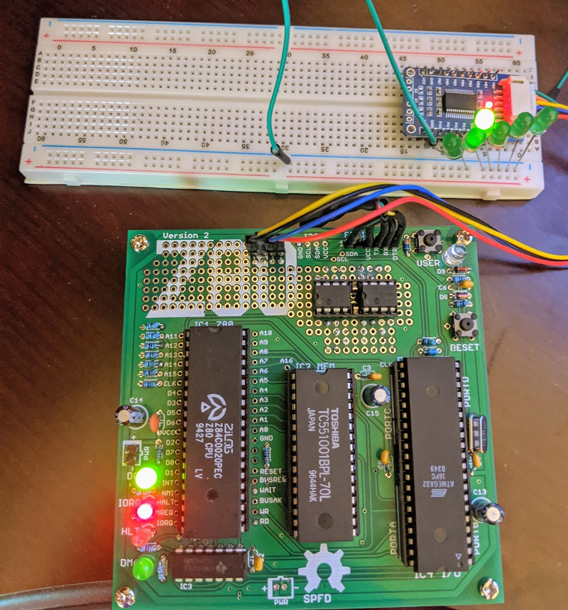
First, you might wonder why I use the IDE. The short answer is I don’t. But when you produce things for other people to use, you almost can’t ignore it. No matter how you craft your personal environment, the minute your code hits the Internet, someone will try to use it in the IDE. A while back I’d written about the $4 Z80 computer by [Just4Fun]. I rarely have time to build things I write about, but I really wanted to try this little computer. The parts sat partially assembled for a while and then a PCB came out for it. I got the PCB and — you guessed it — it sat some more, partially assembled. But I finally found time to finish it and had CP/M booted up.

The only problem was there were not many good options for transferring data back and forth to the PC. It looked like the best bet was to do Intel hex files and transfer them copy and paste across the terminal. I wanted better, and that sent me down a Saturday morning rabbit hole. What I ended up with is a way to make your own menus in the Arduino IDE to set compiler options based on the target hardware for the project. It’s a trick worth knowing as it will come in handy beyond this single problem.

The Issue: Arduino Serial Buffer Size Limit

I won’t bore you with the details about getting the board to work since you will only care if you have one. Details are available in a discussion on Hackaday.io, if you really want to follow it. But the upshot was that for XModem transfers, [Just4Fun] felt like the default Arduino serial buffer wasn’t big enough to be reliable. It did seem to work with the default 64-byte buffer, but XModem sends more data than that and it would be easy to imagine it getting overrun.

How hard can it be to update the buffer? In one way, it is trivial. In another way, it is very difficult because the tools want to help you so badly.

Tool Chain

The little computer project uses a real Z80 chip and uses an ATMega32A for almost all the support functions. It generates the clock, acts like a serial port, acts like a disk drive, and so on. However, the ATMega32 doesn’t directly have Arduino IDE support so you have to install a toolchain for it. The project called for MightyCore so that’s what I used.

The libraries for hardware serial were all set up using #define statements to allow you to adjust the buffer sizes. By default, if you haven’t set up anything, you get a default based on the amount of RAM your processor provides:


#if !defined(SERIAL_TX_BUFFER_SIZE)
#if ((RAMEND - RAMSTART) < 1023)
#define SERIAL_TX_BUFFER_SIZE 16
#else
#define SERIAL_TX_BUFFER_SIZE 64
#endif
#endif
#if !defined(SERIAL_RX_BUFFER_SIZE)
#if ((RAMEND - RAMSTART) < 1023)
#define SERIAL_RX_BUFFER_SIZE 16
#else
#define SERIAL_RX_BUFFER_SIZE 64
#endif
#endif

Making the Change

So this is easy, right? Just define those symbols before HardwareSerial.h loads. Uh oh. That file is loaded by Arduino.h. The IDE wants to add that to your program and it forces it to be first. There seems to be some IDE versions that check if you already included it so they don’t include it twice, but version 1.8.5 didn’t seem to do that. Maybe I can add some options in the preferences to pass to the compiler. Nope. Not via the IDE, anyway.

Not that I didn’t try a lot of things. It was tempting, of course, to simply change the core libraries. But that’s bad. You might want the defaults later. If you update the tool chain, you’ll lose your updates. I wanted to avoid that. Some people on the Internet suggested making a copy of the platform files and modifying those. Still not ideal.

Test Your Assumptions With Custom Error Reporting

I could tell things I tried were not working because I would put #if statements and #error statements temporarily in HardwareSerial.cpp. For example:

#if SERIAL_RX_BUFFER_SIZE==256
#error 256
#endif

Now if a compile causes an error 256, I know I was able to set the size. If not, then the system was resisting my changes.

Compromise: Adding Menu Options At the Board Level

I really wanted a way to make a change just in my project and set the serial buffer sizes. I failed at that. What I did do was make a modification to the boards.txt provided by Mighty Core. Yes, I will have to watch for upgrades overwriting my changes, but they are simple and it will be obvious that it is missing.

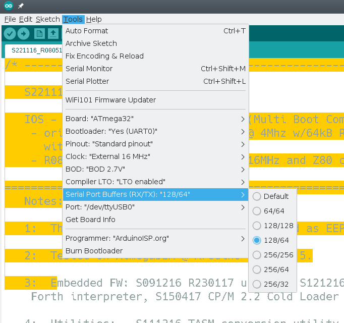
The reason it will be obvious is that I created a menu for the IDE that only appears when using ATMega32 for Mighty Core. This menu lets you select a few preset buffer sizes.

There were three parts to making this work:

  1. You have to tell the IDE you have a menu item and what it looks like.
  2. The new item needs to set some compiler options.
  3. Because the existing system also sets some compiler options, you have to make sure not to clobber them.

The first part is easy. The boards.txt file was (for me) in ~/.arduino15/packages/MightyCore/hardware/avr/2.0.5/boards.txt. Near the top there’s a list of menu keys and I added mine to the end:


# Menu options
menu.clock=Clock
menu.BOD=BOD
menu.LTO=Compiler LTO
menu.variant=Variant
menu.pinout=Pinout
menu.bootloader=Bootloader
menu.SerialBuf=Serial Port Buffers (RX/TX)

Next, I moved down the file and added my menu before the existing LTO menu option for the ATMega32:


32.menu.SerialBuf.disabled=Default
32.menu.SerialBuf.disabled.compilerSB.c.extra_flags=
32.menu.SerialBuf.disabled.compilerSB.cpp.extra_flags=

32.menu.SerialBuf.SB64=64/64
32.menu.SerialBuf.SB64.compilerSB.c.extra_flags=-DSERIAL_RX_BUFFER_SIZE=64 -DSERIAL_TX_BUFFER_SIZE=64
32.menu.SerialBuf.SB64.compilerSB.cpp.extra_flags=-DSERIAL_RX_BUFFER_SIZE=64 -DSERIAL_TX_BUFFER_SIZE=64

32.menu.SerialBuf.SB128=128/128
32.menu.SerialBuf.SB128.compilerSB.c.extra_flags=-DSERIAL_RX_BUFFER_SIZE=128 -DSERIAL_TX_BUFFER_SIZE=128
32.menu.SerialBuf.SB128.compilerSB.cpp.extra_flags=-DSERIAL_RX_BUFFER_SIZE=128 -DSERIAL_TX_BUFFER_SIZE=128

32.menu.SerialBuf.SB12864=128/64
32.menu.SerialBuf.SB12864.compilerSB.c.extra_flags=-DSERIAL_RX_BUFFER_SIZE=128 -DSERIAL_TX_BUFFER_SIZE=64
32.menu.SerialBuf.SB12864.compilerSB.cpp.extra_flags=-DSERIAL_RX_BUFFER_SIZE=128 -DSERIAL_TX_BUFFER_SIZE=64

32.menu.SerialBuf.SB256=256/256
32.menu.SerialBuf.SB256.compilerSB.c.extra_flags=-DSERIAL_RX_BUFFER_SIZE=256 -DSERIAL_TX_BUFFER_SIZE=256
32.menu.SerialBuf.SB256.compilerSB.cpp.extra_flags=-DSERIAL_RX_BUFFER_SIZE=256 -DSERIAL_TX_BUFFER_SIZE=256

32.menu.SerialBuf.SB25664=256/64
32.menu.SerialBuf.SB25664.compilerSB.c.extra_flags=-DSERIAL_RX_BUFFER_SIZE=256 -DSERIAL_TX_BUFFER_SIZE=64
32.menu.SerialBuf.SB25664.compilerSB.cpp.extra_flags=-DSERIAL_RX_BUFFER_SIZE=256 -DSERIAL_TX_BUFFER_SIZE=64

32.menu.SerialBuf.SB25632=256/32
32.menu.SerialBuf.SB25632.compilerSB.c.extra_flags=-DSERIAL_RX_BUFFER_SIZE=256 -DSERIAL_TX_BUFFER_SIZE=32
32.menu.SerialBuf.SB25632.compilerSB.cpp.extra_flags=-DSERIAL_RX_BUFFER_SIZE=256 -DSERIAL_TX_BUFFER_SIZE=32

Menu Structure

You can see that the 32.menu object groups all the items together for this processor. The next part is our menu key (SerialBuf). After that is a unique key for each memory item. It is important that you don’t reuse these. So, for example, if you have two SB64 keys only one is going to work.

If you stop at that key and put an equal sign you can assign the menu item the text you want to display. For example “Default” or “64/64.” You can also extend the key with a property and that property will be set if the option is active.

So, for example, if you select 256/256 then the compilerSB.c.extra_flags property will get set. I made that name up, by the way, and you’ll see why in a minute.

Peaceful Coexistence

There is no property called compilerSB.c.extra_flags. The correct property is compiler.c.extra_flags. However, the Mighty Core LTO option uses the same key. That’s why it was important that the new menu appears first and also that it sets a fake property. Then the LTO code needs a slight modification:


# Compiler link time optimization
32.menu.LTO.Os=LTO disabled
32.menu.LTO.Os.compiler.c.extra_flags={compilerSB.c.extra_flags}
32.menu.LTO.Os.compiler.c.elf.extra_flags=
32.menu.LTO.Os.compiler.cpp.extra_flags={compilerSB.cpp.extra_flags}
32.menu.LTO.Os.ltoarcmd=avr-ar

32.menu.LTO.Os_flto=LTO enabled
32.menu.LTO.Os_flto.compiler.c.extra_flags={compilerSB.c.extra_flags} -Wextra -flto -g
32.menu.LTO.Os_flto.compiler.c.elf.extra_flags=-w -flto -g
32.menu.LTO.Os_flto.compiler.cpp.extra_flags={compilerSB.cpp.extra_flags} -Wextra -flto -g
32.menu.LTO.Os_flto.ltoarcmd=avr-gcc-ar

The big change is that each set of flags adds to whatever the new menu set in its custom property. This way, all the flags get put into the correct property, compiler.c.extra_flags.

I set up error traps to catch all the cases to make sure they were being set right. In addition, after removing those traps, I could see my memory usage go up accordingly.

Customize

Of course, you can modify the parameters if you want something different. You could also use this trick to set other parameters before the Arduino.h file takes over. There’s some documentation about how to set up the platform definitions, including boards.txt.

It would have probably been better for me to make a custom boards.txt file with the same information in it but then I’d need to take the rest of Mighty Core with me. Instead, I just keep a copy of the file called boards.txt.custom and if my menu disappears, I just have to compare that file with the boards.txt file to see what changed.

Of course, if you don’t have to support people using the IDE, maybe just give it up. The Pro IDE is better, even if it does have some shortcomings. Plus there’s always Platform.io.
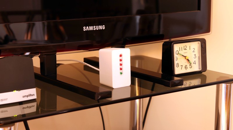
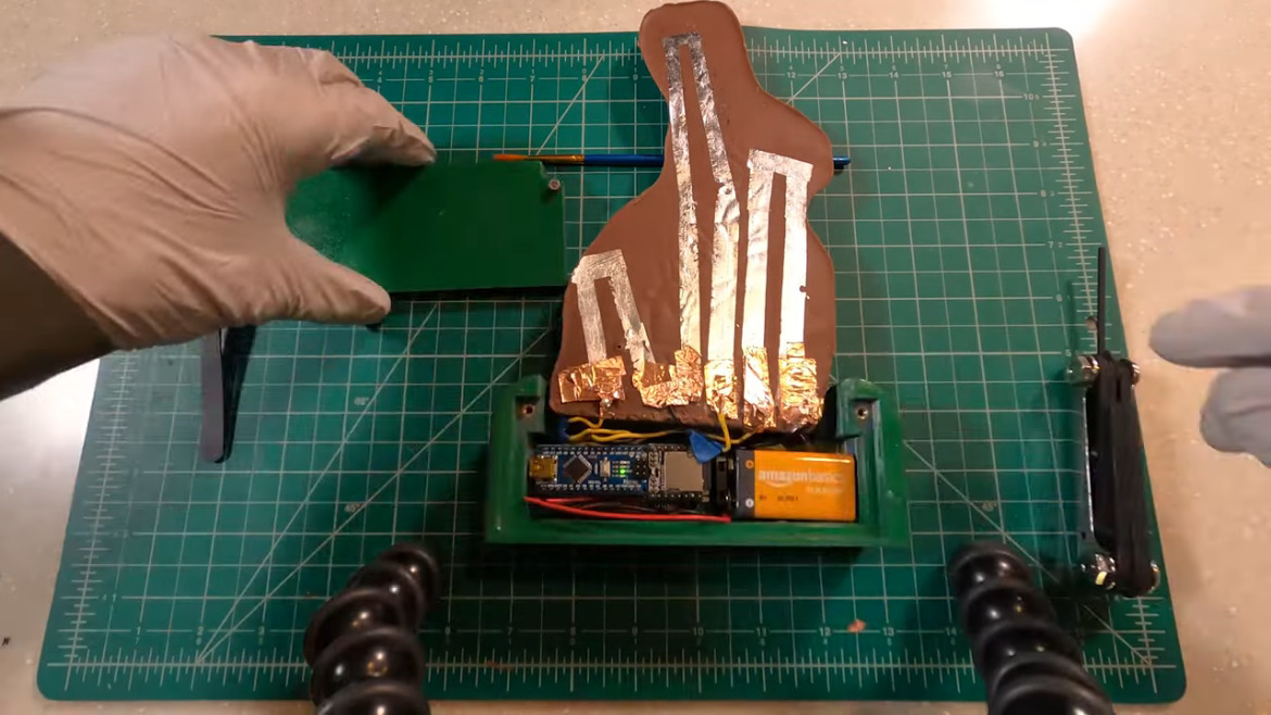
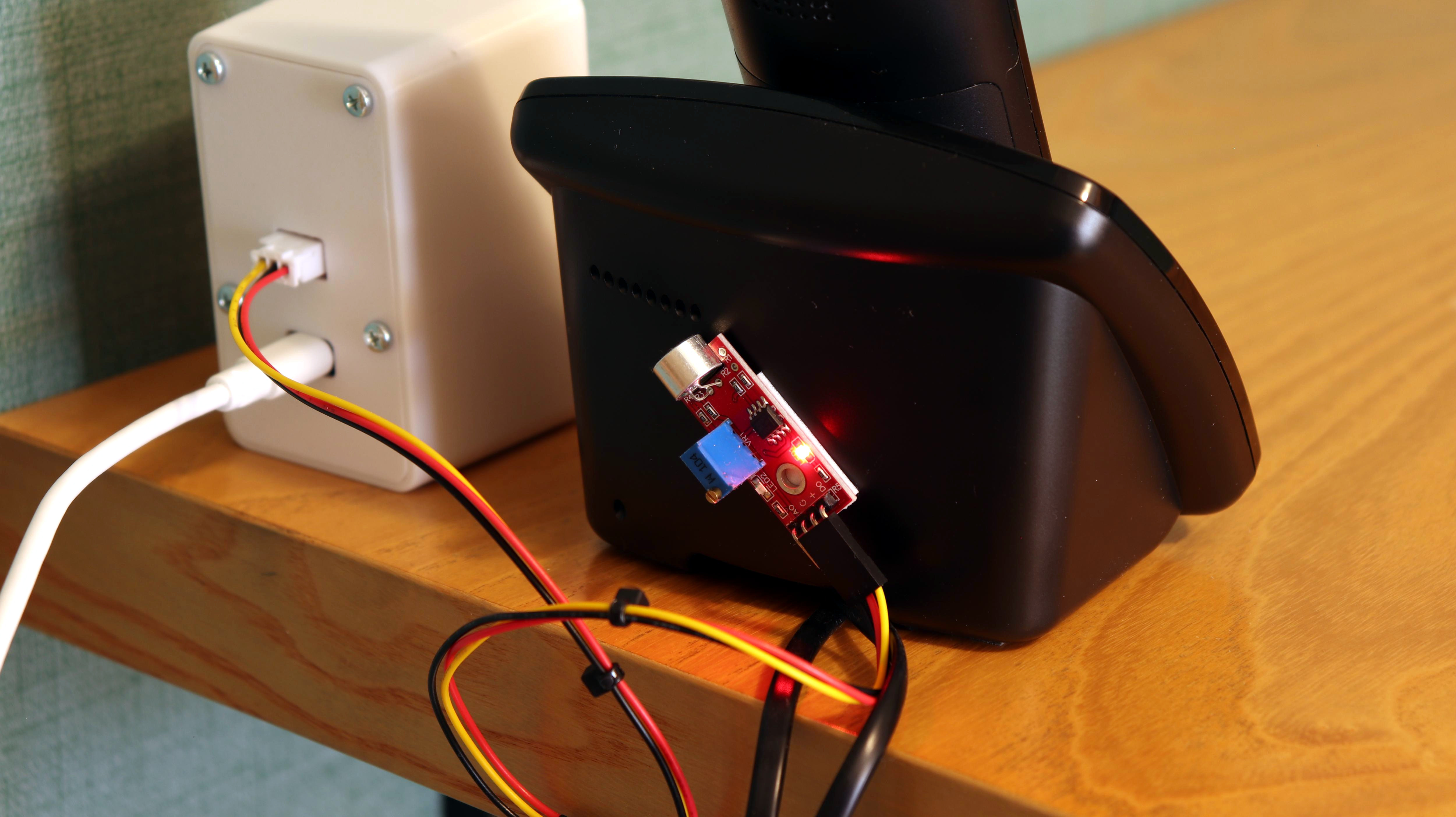
How To Hack A Portable Bluetooth Speaker By Skipping The Bluetooth

Portable Bluetooth speakers have joined the club of ubiquitous personal electronics. What was once an expensive luxury is now widely accessible thanks to a prolific landscape of manufacturers mass producing speakers to fit every taste and budget. Some have even become branded promotional giveaway items. As a consequence, nowadays it’s not unusual to have a small collection of them, a fertile field for hacking.

But many surplus speakers are put on a shelf for “do something with it later” only to collect dust. Our main obstacle is a side effect of market diversity: with so many different speakers, a hack posted for one speaker wouldn’t apply to another. Some speakers are amenable to custom firmware, but only a small minority have attracted a software development community. It doesn’t help that most Bluetooth audio modules are opaque, their development toolchains difficult to obtain.

So what if we just take advantage of the best parts of these speakers: great audio fidelity, portability, and the polished look of a consumer good, to serves as the host for our own audio-based hacks. Let’s throw the Bluetooth overboard but embrace all those other things. Now hacking these boxes just requires a change of mindset and a little detective work. I’ll show you how to drop an Arduino into a cheap speaker as the blueprint for your own audio adventures.

Directing the Hacker Mindset at Myriad Bluetooth Speakers

There’s way too many different speakers out there for one hack to rule them all. But by changing our Bluetooth speaker mindset from “it’s a reprogrammable computer” to “it’s an integrated collection of useful electronic components”, we turn market diversity into our ally.

Look at this from the perspective of Bluetooth speaker manufacturers: they want their Bluetooth speaker to stand out from competitors, and the most obvious way is in their selection of loudspeaker drivers. Surprising the customer with big sound from a little box is key for success, so each product can offer a unique combination for driving the audio, all housed inside an eye-catching enclosure that lets consumers tell one portable Bluetooth speaker from another.

Tailoring for loudspeaker selection has cascading effects through the rest of the system. For best sound, they will need matching audio amplifier modules, which will have their own power requirements, which dictates battery performance, and so on. Catering to these desires, components are excluded from the tightly integrated mystery black boxes. Fortunately for hardware hackers, such an architecture also makes components easy to reuse:

  1. A rechargeable battery.
  2. Ability to charge that battery from USB.
  3. A low-power standby mode to monitor press of the power button.
  4. Protecting battery from over-discharge.
  5. A voltage regulator supplying battery power to the device.
  6. An audio line-in jack.
  7. Volume up/down control.
  8. Amplifier and driver.

All of these are useful for projects, already neatly packaged in a mass-produced enclosure.

Putting Theory Into Practice With An Example

Now that we have a general background, let’s apply this concept to a specific example. But before we begin, an obligatory note in case it is not obvious to any beginners reading this: This activity very definitely voids the warranty (do it, it’s worth it!), and modern portable electronics use lithium chemistry batteries that can be dangerous if mistreated.

The Bluetooth speaker used in this example is a “Rugged Portable Bluetooth Speaker” sold by North American electronics retailer Best Buy under one of their house brands. A search of its FCC ID pointed to Lightcomm Technology Co. as the manufacturer. The “rugged” claim starts with a layer of soft rubber wrapped around its exterior. That plus reinforcements inside the case allows the speaker to absorb some level of abuse. I wanted to preserve this shock absorbing exterior and, thankfully, it was easy to open non-destructively. Even more care would be needed if it was a waterproof speaker (this one wasn’t) and moisture barriers need to be preserved. Alternatively, if the plan is to transfer the internals to another enclosure, the condition of the original box would not matter.

Once the circuit board has been extracted, the Bluetooth interface module should immediately stand out as the most sophisticated component sitting close to an antenna. A search for ATS2823 confirmed it is a module designed and sold for integration into Bluetooth audio products. Its MIPS M4K core and associated flash storage could be a promising start for firmware hacking, but the point of this example is to demonstrate how to hack a speaker utilizing existing firmware. So we will leave the module as-is.

Solder to the External Audio Input

The easiest way to pipe audio into this system is to pretend to be an external audio source. We want the system to believe we are connected via an audio cable plugged into the line-in jack, but for compactness we’d prefer to do this without using an actual cord. This approach is easy, nondestructive, and preserves the existing volume control mechanism. There are a lot of different ways to implement an audio jack, so some exploration with a multimeter will be required. We need to find the standardized contacts for: audio input left channel, right channel, and ground. (Wikipedia reference: “Phone connector (audio)“)

It’ll be a little tricker to decipher the plug detection scheme, as it is not standardized. In this particular example, there is a fourth pin that floats in the absence of an audio plug. When an audio plug is present, the pin is grounded. Soldering a wire to always ground that detection pin will keep this speaker constantly in “playing external audio” mode.

Or Connect To Amplifier Directly

An alternative approach is to bypass existing input and volume control, sending audio directly to the amplifier chip. To find this chip, we start with the voice coil wires and backtrack. It’ll likely be the largest component near those voice coil wires. Once the amplifier chip is found, consult the datasheet to find the input pins to cut free from the circuit and rewire for audio input that bypasses existing control.

But even if we wish to maintain existing volume control, it is still useful to locate the audio amplifier chip. It is the most power-hungry component on the circuit board, and peak power requirements for the system are dictated by the amount of power this amplifier will draw when playing loudly. Therefore it is half the puzzle of calculating our available power. This particular Bluetooth device uses a Mixinno MIX2052 chip sitting adjacent to the voice coil wire connector, with a peak power of 6 watts.

Tap Into Power Supply

The other half of the puzzle is the voltage regulator delivering power to the amplifier chip. Similar to how we look for our amplifier near our voice coil wires, we can look for our regulator sitting near inductors, capacitors, and diodes. Once the power module is found, read its data sheet to determine peak power output.

The power budget for our hack would be constrained by power figures for those two components. Most microcontrollers consume maximum power during bootup. So as long as the audio source stays quiet during this time, we would have a little extra power to support boot. Somewhere between the regulator and the amplifier is also the best place to tap power. It allows us to piggyback on the existing power management circuit that shuts down the amplifier when entering low power mode, cutting power to our hack at the same time.

In the case of this board, there was one prominent coil and a Techcode TD8208 step-up regulator was found next to it. Configured to deliver 5 volts, this regulator can deliver 1A and tolerate brief spikes not to exceed 2A. This wouldn’t be enough to feed a Raspberry Pi 4, but plenty for an Arduino Nano.

Repurpose Control Button

So far functionality for three of the four buttons on this speaker has been preserved: power, volume up, and volume down. The fourth button initiates Bluetooth pairing, or to pick up a phone call. We’re cutting BT out of the equation so this is no longer useful and can be repurposed.

On this speaker, SW4 is normally open and pulls to ground when pressed, making it trivial to reuse. I cut the trace leading to the Bluetooth interface module and soldered a wire so the switch now pulls an Arduino pin to ground when pressed.

Tuck Everything Back In

A few pieces of internal plastic reinforcements for ruggedness were cut away to create enough volume for an Arduino Nano inside this enclosure. It is no longer quite as rugged, but now it is far more interesting as a platform for sound hacks. To conclude this proof of concept, the Arduino Nano is using the Mozzi audio library to play the classic Wilhelm scream whenever our repurposed button is pressed.


Build Your Own Bleepy Bloopy Buzzy Box

Bluetooth used to be the novelty. With plenty of hacks adding Bluetooth to existing audio equipment, playing Bluetooth audio out of one, or building our own Bluetooth speakers from scratch. But now Bluetooth speakers are ubiquitous, we’re approaching the point where Bluetooth is not necessarily the center of attention. Skipping the Bluetooth in a portable Bluetooth speaker gives us a new platform for our noise maker hacks. Something small, fun, and easy to bring to our next hacker show-and-tell meetup!

A Custom Keyboard At Maximum Effort

No one loves hacked keyboards more than Hackaday. We spend most of our workday pressing different combinations of the same 104 buttons. Investing time in that tool is time well spent. [Max] feels the same and wants some personality in his input device.

In the first of three videos, he steps us through the design and materials, starting with a layer to hold the keys. FR4 is the layer of fiberglass substrate used for most circuit boards. Protoboards with no copper are just bare FR4 with holes. Homemade CNC machines can glide through FR4, achieving clean lines, and the material comes in different mask colors so customizing an already custom piece is simple. We see a couple of useful online tools for making a homemade keyboard throughout the videos. The first is a keypad layout tool which allows you to start with popular configurations and tweak them to suit your weirdest desires. Missing finger? Forget one key column. Extra digit? Add a new key column. Huge hands? More spaces between the keys. [Max] copied the Iris keyboard design but named his Arke, after the fraternal sister to Iris which is fitting since his wrist rests are removable.

In the second video, we see how the case and a custom cable are designed. One of the most beautiful features of this build is the cable with 3D-printed boots that are sized to fit ordinary pin headers. The homemade keyboard that this article is being typed on just has a piece of yellow Cat5 between the halves. When the custom cable is assembled, we see a hack revealed by accident. Twelve wires for the cable are salvaged from some ribbon cable and by cutting the ribbon straight across, every scrap of wire is the same length. No more of those unruly wires at the end or that one short one that kinks all the others. There is also a cable boot design that didn’t make the final cut but featured some secure threaded ends that are still available for download.

Another bonus hack comes from the calipers used to break wires into subsections. Check out how to make your calipers run for years on a singe battery. Keyswitch wiring is explained in the final video, shown below, which is simple enough since it is a row-and-column arrangement. The third bonus hack is when we see that classic gray ribbon “stripped” by applying a hot iron to the tip. [Max], like others, has a video about making helping hands from coolant hoses, but here he chooses the more straightforward route of putting some gummy tack on the table and mashing the header into it. Like the shortcut with the keyboard layout design, an online tool generates the firmware.

When you are ready to make your own keyboard, you will be in good hands with time-tested methods or even 3D printing. If you like the regular design, you can also overhaul an old keyboard, or update a USB device to Bluetooth.

PID Control with Arduino

Experience — or at least education — often makes a big difference to having a successful project. For example, if you didn’t think about it much, you might think it is simple to control the temperature of something that is heating. Just turn on the heater if it is cold and turn it off when you hit the right temperature, right? That is one approach — sometimes known as bang-bang — but you’ll find there a lot of issues with that approach. Best practice is to use a PID or Proportional/Integral/Derivative control. [Electronoob] has a good tutorial about how to pull this off with an Arduino. You can also see a video, below.

The demo uses a 3D printer hot end, a thermocouple, a MAX6675 that reads the thermocouple, and an Arduino. There’s also an LCD display and a FET to control the heater.

The idea behind a PID controller is that you measure the difference between the current temperature and the desired temperature known as the setpoint. The proportional gain tells you how much output occurs due to that difference. So if the setpoint is way off, the proportional term will generate a lot of output to the heater. If it is close, only a little bit of output will result. This helps prevent overshoot where the temperature goes too high and has to come back down.

The integral term adds a little bit to the output based on the cumulative error over time. The derivative term reacts to changes in the temperature difference. For example, if something external causes the temperature to drop suddenly, the derivative term can goose the output to compensate.

However, the operative word is “can.” Part of setting up a PID is finding the coefficients for each term which for some systems could be zero or even negative (indicating a reverse effect).  There are a lot of other subtleties, too, like what happens if the output stops affecting the temperature for a long period and the integral amount grows to unmanageable magnitude.

By the way, we’ve covered a PID library for Arduino before. While this post talks about temperature, PID control is used for everything from flight control to levitation.

Hack a Day 14 Apr 09:00

Glorious Body of Tracked ‘Mad Mech’ Started as Cardboard

[Dickel] always liked tracked vehicles. Taking inspiration from the ‘Peacemaker’ tracked vehicle in Mad Max: Fury Road, he replicated it as the Mad Mech. The vehicle is remote-controlled and the tank treads are partly from a VEX robotics tank tread kit. Control is via a DIY wireless controller using an Arduino and NRF24L01 modules. The vehicle itself uses an Arduino UNO with an L298N motor driver. Power is from three Li-Po cells.

The real artistic work is in the body. [Dickel] used a papercraft tool called Pepakura (non-free software, but this Blender plugin is an alternative free approach) for the design to make the body out of thin cardboard. The cardboard design was then modified to make it match the body of the Peacemaker as much as possible. It was coated in fiberglass for strength, then the rest of the work was done with body filler and sanding for a smooth finish. After a few more details and a good paint job, it was ready to roll.

There’s a lot of great effort that went into this build, and [Dickel] shows his work and process on his project page and in the videos embedded below. The first video shows the finished Mad Mech being taken for some test drives. The second is a montage showing key parts of the build process.

Paper and cardboard are very versatile and accessible materials for making things. It’s what was used to do some target practice with this working paper and cardboard gun. With the right techniques foam core can be worked into an astonishing variety of shapes, and we also made a case for the value of a desktop vinyl cutter on any well-equipped hacker’s workbench.