Posts with «matrix» label

Matrix and Joystick

For the original tutorial, please visit: https://arduinobasics.blogspot.com


Project Description

In this project, we will use a little joystick to move a pixel around an 8x8 LED matrix. The joystick has a built-in button, such that when you press down onto the joystick, the colour of the pixel will change from red to blue to green. This is a very simple project, however, controlling the matrix adds a certain level of complexity. You will need to understand binary notation and bit-shifting techniques to grasp the concept of this tutorial.

All of the parts used in this project can be obtained from digitspace.com


Libraries

The SPI library is required for this project. However, this library is built into the current version of the Arduino IDE. No additional download is required. Just make sure to include it at the top of the sketch.


Arduino Code

The Arduino IDE can be downloaded from the official Arduino website: here.
Copy and paste the following code into your Arduino IDE and upload it to the Arduino UNO.
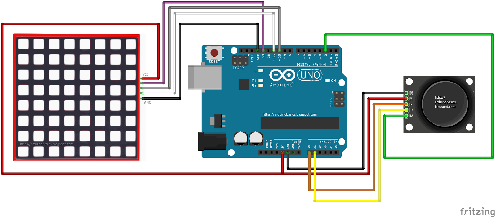


Connections


Project Video

As you can see from the video above, the pixel changes colour when the button is pressed. The position of the pixel relates to the position of the joystick. The lag between the joystick movement and pixel movement is minimal, and very satisfying.


Conclusion

This was a very fun and satisfying project that showcases the interaction between a joystick and a 8x8 LED matrix with the help of an Arduino UNO. This project was sponsored by the kind people at digitspace. Without their sponsorship, this tutorial would not have been possible. Please visit their website for some nice deals on Arduino related products.

If you found this tutorial helpful, please consider supporting me by buying me a virtual coffee/beer.

$3.00 AUD only

Social Media

You can find me on various social networks:

Follow me on Twitter: ScottC @ArduinoBasics.
I can also be found on Instagram, Pinterest, and YouTube.
And if all else fails, I have a server on Discord.


ScottC 09 Mar 07:41
8x8  arduino  ce  clk  fun  joystick  led  matrix  module  mosi  pixel  programming  spi  sw  tutorial  uno  x  y  

A Farewell To YouTube Sub Counters Set To Break With API Change

Of all the things you never would have guessed you’d need just ten years ago, a YouTube subscriber counter would probably rank highly. You would have guessed that the little hits of dopamine accompanying each tick upward of a number would be so addictive?

As it turns out, lots of people wanted to keep a running total of their online fans, and a bewilderingly varied ecosystem of subscriber counters has cropped up. All of them rely on the API that YouTube exposes for such purposes, which as [Brian Lough] points out is about to change and break every subscription counter ever made. In the YouTube sub counter space, [Brian] is both an enabler – he built an Arduino wrapper to fetch YT sub counts easily – and a serial builder of displays for other YouTubers. The video below shows a collection of his work, many based on RGB LED matrix display, like the one used in his Tetris-themed sub counter. They’re all well-built, nice to look at, and sadly, destined for obsolescence sometime in August when the API changes.

The details of the API changes were made public in April, and for the subs count it amounts to rounding the count and displaying large counts as, for instance, 510k as opposed to 510,023. We’re confident that [Brian] and other display builders will be able to salvage some of their counters with code changes, but others will probably require hardware changes. Thanks, YouTube.

Hack a Day 02 Aug 03:00

A Ping Pong Ball LED Video Wall

Constrained builds are often the most fun. Throw an artificial limit into the mix, like time limiting your effort or restricting yourself to what’s on hand, and there’s no telling what will happen.

[bitluni] actually chose both of those constraints for this ping pong ball LED video display, and the results are pretty cool, even if the journey was a little rough. It seems like using sheet steel for the support of his 15 x 20 Neopixel display was a mistake, at least in hindsight. A CNC router would probably have made the job of drilling 300 holes quite a bit easier, but when all you have is a hand drill and a time limit, you soldier on. Six strings of Neopixels fill the holes, a largish power supply provides the 18 or so amps needed, and an Arduino knock-off controls the display. The ping pong ball diffusers are a nice touch, even if punching holes in them cost [bitluni] a soldering iron tip or two. The display is shown in action in the video below, mostly with scrolling text. If we may make a modest suggestion, a game of Pong on a ping pong ball display might be fun.

[bitluni] says that the display is on its way to Maker Faire Berlin this weekend, so stop by and say hi. Maybe he’ll have some of his other cool builds too, like his Sony Watchman Game Boy mashup, or the electric scooter of questionable legality.

Hack a Day 17 May 16:30

Hackaday Prize Entry: ESPMetric, a Simple and Easy Matrix

There’s a lot you can do with a bunch of LEDs connected to the Internet. You can display the time, the weather, the bus schedule, or any one of a number of important data points in your life. Custom matrices are a pain in the butt to set up, which is why we like to see one looking rather polished and clean. [Faire-soi-meme] prettied up an 8×32 NeoPixel matrix with some diffusers and a grid bezel. It’s the ESPMetric, and it’s also an entry for this year’s Hackaday Prize.

The NeoPixel matrix is controlled by a NodeMcu using elements from [squix78]’s ESP82666 weather station code as well as Adafruit’s NeoMatrix library. There is a photoresistor to control brightness as well as 3 buttons to control its various modes. Tapping the buttons brings you by various settings like the time, WiFi status, stock market, and so on.

If you parlez-vous français–or enjoy the Google Translate experience–[Faire-soi-meme] has detailed the build steps on his blog, though you can also download his code from his GitHub repository. There’s a great video of this build, you can check that out below.


Filed under: The Hackaday Prize

Cellular Automata Explorer

Well all know cellular automata from Conway’s Game of Life which simulates cellular evolution using rules based on the state of all eight adjacent cells. [Gavin] has been having fun playing with elementary cellular automata in his spare time. Unlike Conway’s Game, elementary automata uses just the left and right neighbors of a cell to determine the next cell ahead in the row. Despite this comparative simplicity, some really complex patterns emerge, including a Turing-complete one.

[Gavin] started off doing the calculations by hand for fun. He made some nice worksheets for this. As we can easily imagine, doing the calculations by hand got boring fast. It wasn’t long before his thoughts turned to automating his cellular automata. So, he put together an automatic cellular automator. (We admit, we are having a bit of fun with this.)

This could have been a quick software project but half the fun is seeing the simulations on a purpose-built ecosystem. The files to build the device are hosted on Thingiverse. Like other cellular automata projects, it uses LED matrices to display the data. An Arduino acts as the brain and some really cool retro switches from the world’s most ridiculously organized electronics collection finish the look of the project.

To use, enter the starting condition with the switches at the bottom. The code on the Arduino then computes and displays the pattern on the matrix. Pretty cool and way faster than doing it by hand.


Filed under: Arduino Hacks, misc hacks

“Arduino Borealis” Combines LEDs and Paint

[Stef Cohen] decided to combine three different artistic mediums for her latest project. Those are painting, electronics, and software. The end goal was to recreate the aurora borealis, also known as the northern lights, in a painting.

The first step was to make the painting. [Stef] began with a shadow box. A shadow box is sort of like a picture frame that is extra deep. A snowy scene was painted directly onto the front side of the glass plate of the shadow box using acrylic paint. [Stef] painted the white, snowy ground along with some pine trees. The sky was left unpainted, in order to allow light to shine through from inside of the shadow box. A sheet of vellum paper was fixed to the inside of the glass pane. This serves to diffuse the light from the LEDs that would eventually be placed inside the box.

Next it was time to install the electronics. [Stef] used an off-the-shelf RGB LED matrix from Adafruit. The matrix is configured with 16 rows of 32 LEDs each. This was controlled with an Arduino Uno. The LED matrix was mounted inside the shadow box, behind the vellum paper. The Arduino code was easily written using Adafruit’s RGB Matrix Panel library.

To get the aurora effect just right, [Stef] used a clever trick. She took real world photographs of the aurora and pixelated them using Photoshop. She could then sample the color of each pixel to ensure that each LED was the appropriate color. Various functions from the Adafruit library were used to digitally paint the aurora into the LED matrix. Some subtle animations were also included to give it an extra kick.


Filed under: Arduino Hacks, led hacks

Arduino Tetris on a Multiplexed LED Matrix

[Alex] needed a project for his microcomputer circuits class. He wanted something that would challenge him on both the electronics side of things, as well as the programming side. He ended up designing an 8 by 16 grid of LED’s that was turned into a game of Tetris.

He arranged all 128 LED’s into the grid on a piece of perfboard. All of the anodes were bent over and connected together into rows of 8 LED’s. The cathodes were bent perpendicularly and forms columns of 16 LED’s. This way, if power is applied to one row and a single column is grounded, one LED will light up at the intersection. This method only works reliably to light up a single LED at a time. With that in mind, [Alex] needed to have a very high “refresh rate” for his display. He only ever lights up one LED at a time, but he scans through the 128 LED’s so fast that persistence of vision prevents you from noticing. To the human eye, it looks like multiple LED’s are lit up simultaneously.

[Alex] planned to use an Arduino to control this display, but it doesn’t have enough outputs on its own to control all of those lights. He ended up using multiple 74138 decoder/multiplexer IC’s to control the LED’s. Since the columns have inverted outputs, he couldn’t just hook them straight up to the LED’s. Instead he had to run the signals through a set of PNP transistors to flip the logic. This setup allowed [Alex] to control all 128 LED’s with just seven bits, but it was too slow for him.

His solution was to control the multiplexers with counter IC’s. The Arduino can just increment the counter up to the appropriate LED. The Arduino then controls the state of the LED using the active high enable line from the column multiplexer chip.

[Alex] wanted more than just a static image to show off on his new display, so he programmed in a version of Tetris. The controller is just a piece of perfboard with four push buttons. He had to work out all of the programming to ensure the game ran smoothly while properly updating the screen and simultaneously reading the controller for new input. All of this ran on the Arduino.

Can’t get enough Tetris hacks? Try these on for size.


Filed under: Arduino Hacks, led hacks

What is the Matrix…Clock?

We’re surprised we haven’t seen this kind of clock before, or maybe we have, but forgot about it in the dark filing cabinets of our minds. The above picture of [danjhamer’s] Matrix Clock doesn’t quite do it justice, because this is a clock that doesn’t just tick away and idly update the minutes/hours.

Instead, a familiar Matrix-esque rain animation swoops in from above, exchanging old numbers for new. For the most part, the build is what you would expect: a 16×8 LED Matrix display driven by a TLC5920 LED driver, with an Arduino that uses a DS1307 RTC (real-time clock) with a coin cell battery to keep track of time when not powered through USB. [danjhamer] has also created a 3D-printed enclosure as well as added a piezo speaker to allow the clock to chime off customizable musical alarms.

You can find schematics and other details on his Hackaday.io project page, but first, swing down below the jump to see more of the clock’s simple but awesome animations.


Filed under: Arduino Hacks, clock hacks

Micro Word Clock

A word clock – a clock that tells time with words, not dials or numbers – is one of those builds that’s on every Arduino neophyte’s ‘To Build’ list. It’s a bit more complex than blinking a LED, but an easily attainable goal that’s really only listening to a real time clock and turning a few LEDs on and off in the right pattern.

One of the biggest hurdles facing anyone building a word clock is the construction of the LED matrix; each LED or word needs to be in its own light-proof box. There is another option, and it’s something we’ve never seen before: you can just buy 8×8 LED matrices, so why not make a word clock out of that? That’s what [Daniel] did, and the finished project is just crying out to be made into a word watch.

[Daniel]’s word clock only uses eight discrete components: an ATMega328p, a DS1307 real time clock, some passives, and an 8×8 LED matrix. A transparency sheet with printed letters fits over the LED matrix forming the words, and the entire device isn’t much thicker than the LED matrix itself.

All the files to replicate this build can be found on [Daniel]’s webpage, with links to the Arduino code, the EAGLE board files, and link to buy the board on OSH Park.


Filed under: clock hacks
Hack a Day 29 Nov 09:00

Project: Clock Four – Scrolling text clock

Introduction

Time for another instalment in my highly-irregular series of irregular clock projects.  In this we have “Clock Four” – a scrolling text clock. After examining some Freetronics Dot Matrix Displays in the stock, it occurred to me that it would be neat to display the time as it was spoken (or close to it) – and thus this the clock was born. It is a quick project – we give you enough to get going with the hardware and sketch, and then you can take it further to suit your needs.

Hardware

You’ll need three major items – An Arduino Uno-compatible board, a real-time clock circuit or module using either a DS1307 or DS3232 IC, and a Freetronics DMD. You might want an external power supply, but we’ll get to that later on.

The first stage is to fit your real-time clock. If you are unfamiliar with the operation of real-time clock circuits, check out the last section of this tutorial. You can build a RTC circuit onto a protoshield or if you have a Freetronics Eleven, it can all fit in the prototyping space as such:

If you have an RTC module, it will also fit in the same space, then you simply run some wires to the 5V, GND, A4 (for SDA) and A5 (for SCL):

By now I hope you’re thinking “how do you set the time?”. There’s two answers to that question. If you’re using the DS3232 just set it in the sketch (see below) as the accuracy is very good, you only need to upload the sketch with the new time twice a year to cover daylight savings (unless you live in Queensland). Otherwise add a simple user-interface – a couple of buttons could do it, just as we did with Clock Two. Finally you just need to put the hardware on the back of the DMD. There’s plenty of scope to meet your own needs, a simple solution might be to align the control board so you can access the USB socket with ease – and then stick it down with some Sugru:

With regards to powering the clock – you can run ONE DMD from the Arduino, and it runs at a good brightness for indoor use. If you want the DMD to run at full, retina-burning brightness you need to use a separate 5 V 4 A power supply. If you’re using two DMDs – that goes to 8 A, and so on. Simply connect the external power to one DMD’s terminals (connect the second or more DMDs to these terminals):

The Arduino Sketch

You can download the sketch from here. Please use IDE v1.0.1 . The sketch has the usual functions to set and retrieve the time from DS1307/3232 real-time clock ICs, and as usual with all our clocks you can enter the time information into the variables in void setup(), then uncomment setDateDs1307(), upload the sketch, re-comment setDateDs1307, then upload the sketch once more. Repeat that process to re-set the time if you didn’t add any hardware-based user interface.

Once the time is retrieved in void loop(), it is passed to the function createTextTime(). This function creates the text string to display by starting with “It’s “, and then determines which words to follow depending on the current time. Finally the function drawText() converts the string holding the text to display into a character variable which can be passed to the DMD.

And here it is in action:

Conclusion

This was a quick project, however I hope you found it either entertaining or useful – and another random type of clock that’s easy to reproduce or modify yourself. We’re already working on another one which is completely different, so stay tuned.

In the meanwhile have fun and keep checking into tronixstuff.com. Why not follow things on twitterGoogle+, subscribe  for email updates or RSS using the links on the right-hand column? And join our friendly Google Group – dedicated to the projects and related items on this website. Sign up – it’s free, helpful to each other –  and we can all learn something.

The post Project: Clock Four – Scrolling text clock appeared first on tronixstuff.