Posts with «wifichron» label

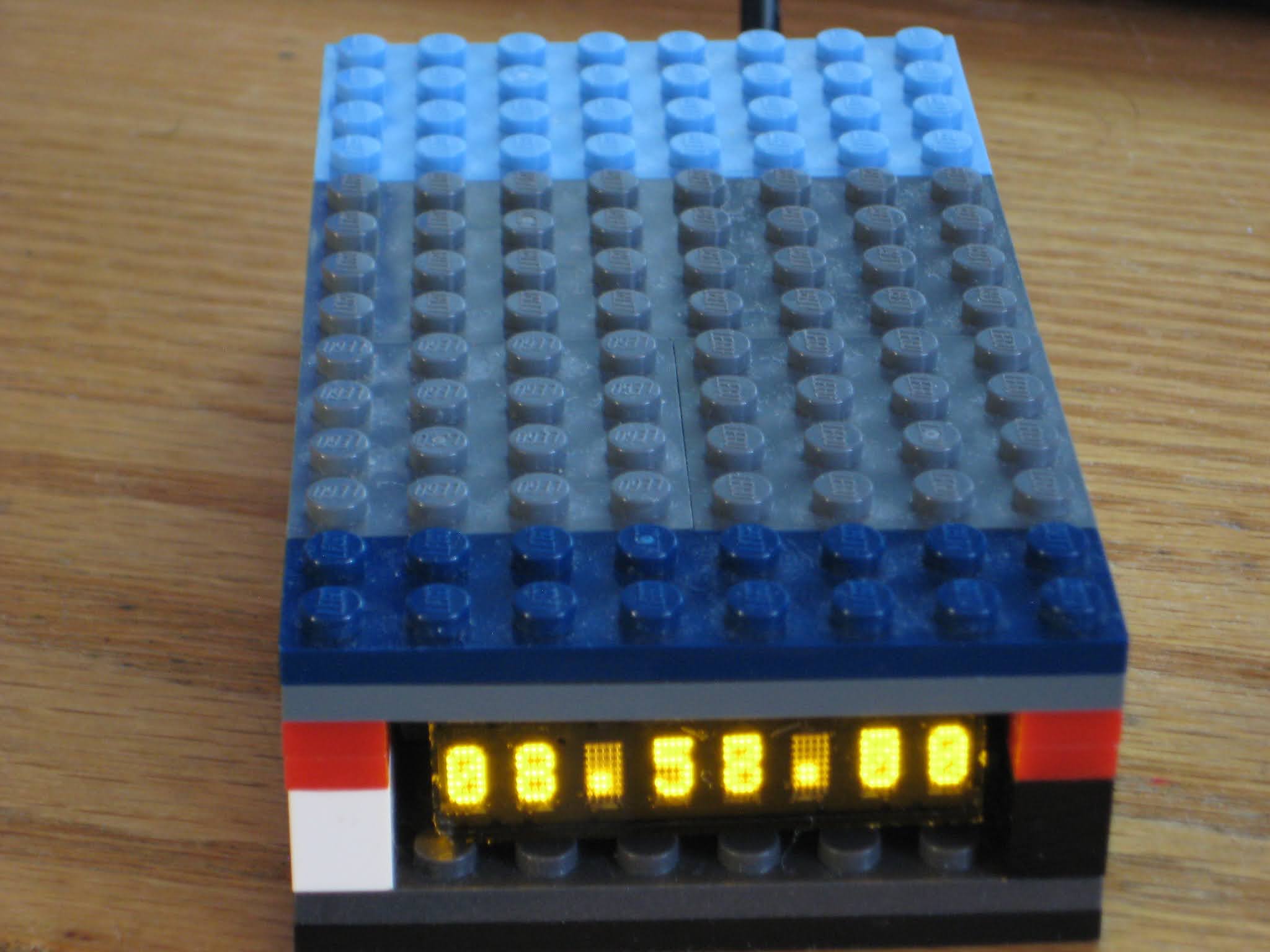
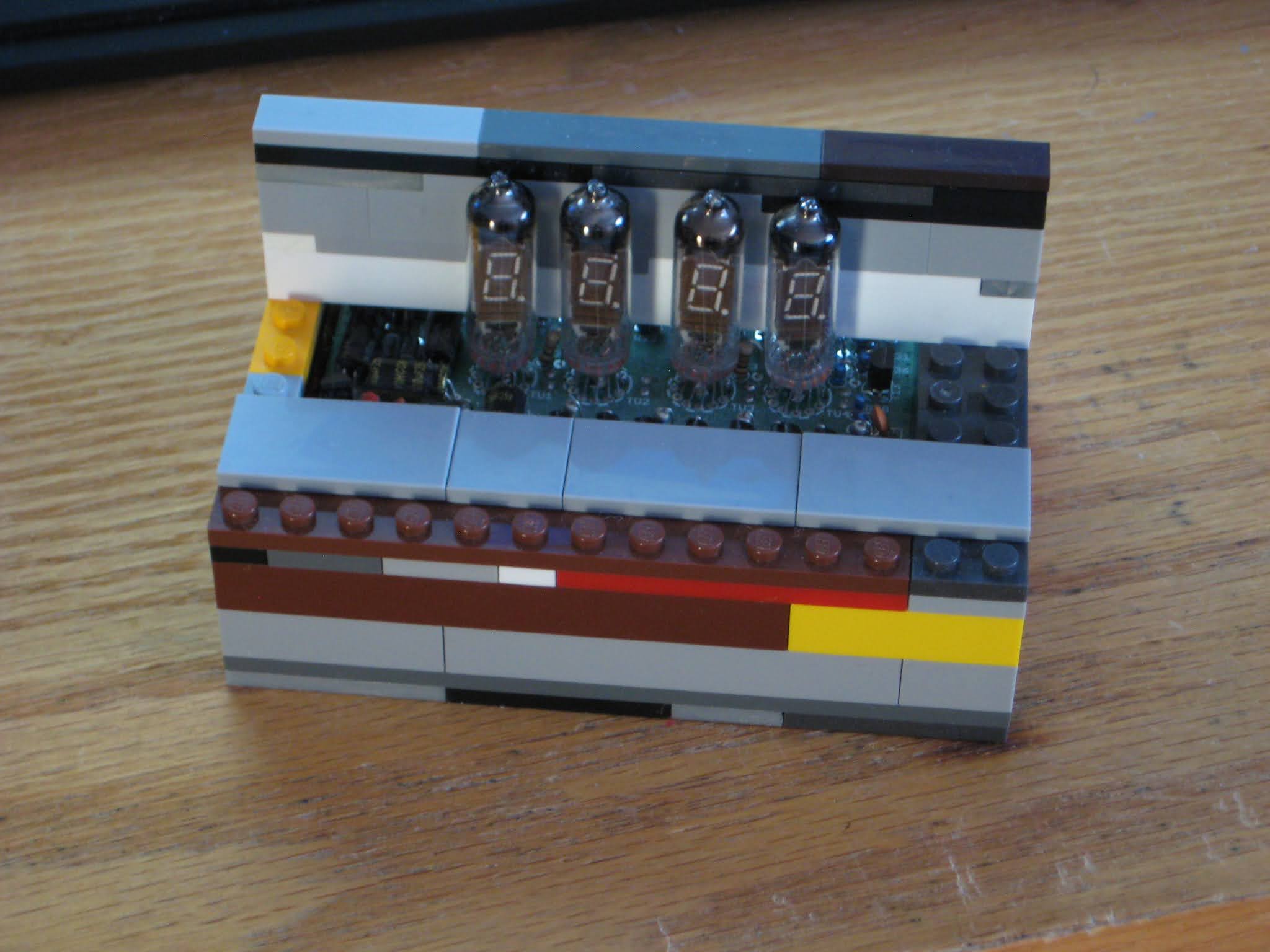
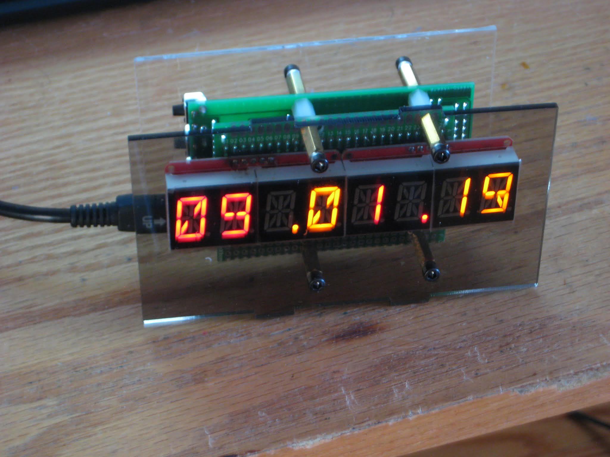
Great 8 character fluorescent (VFD) display

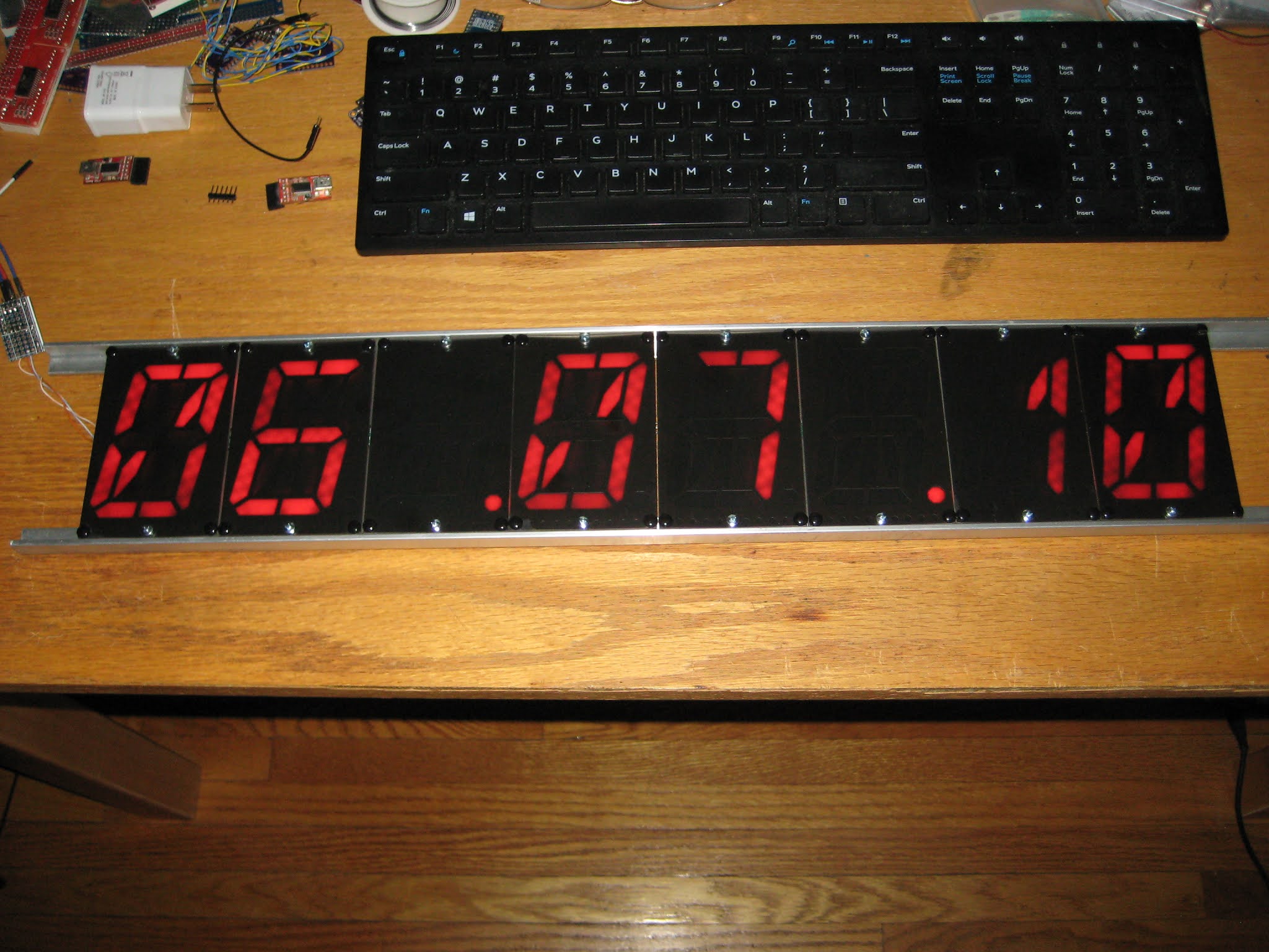
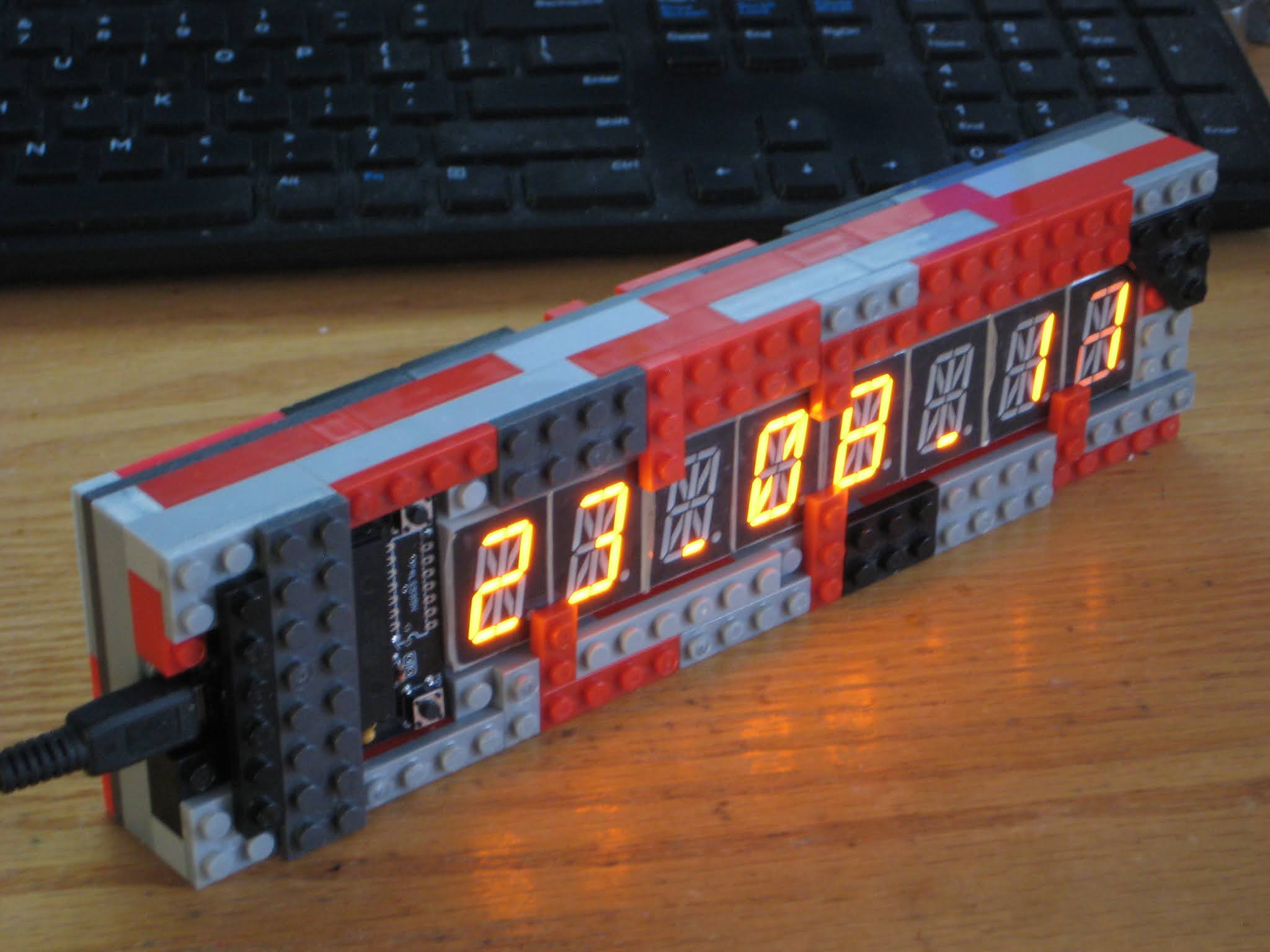
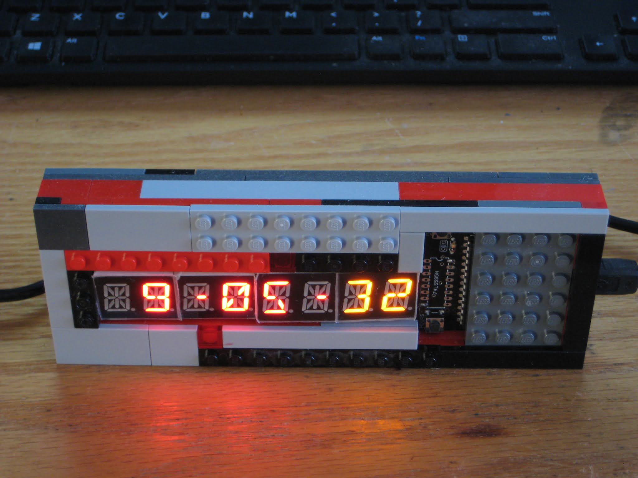
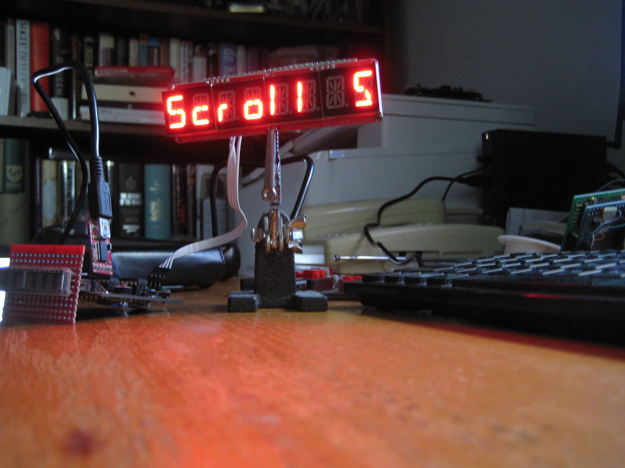
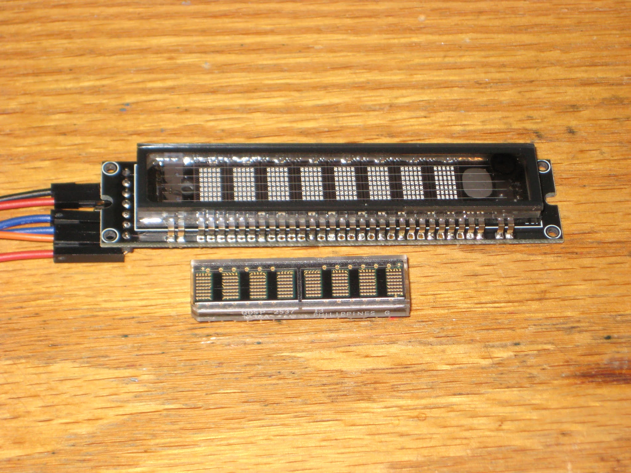
 In the process of expanding the family of supported displays for the WiFiChron clock, I found this amazing VFD module on aliexpress:

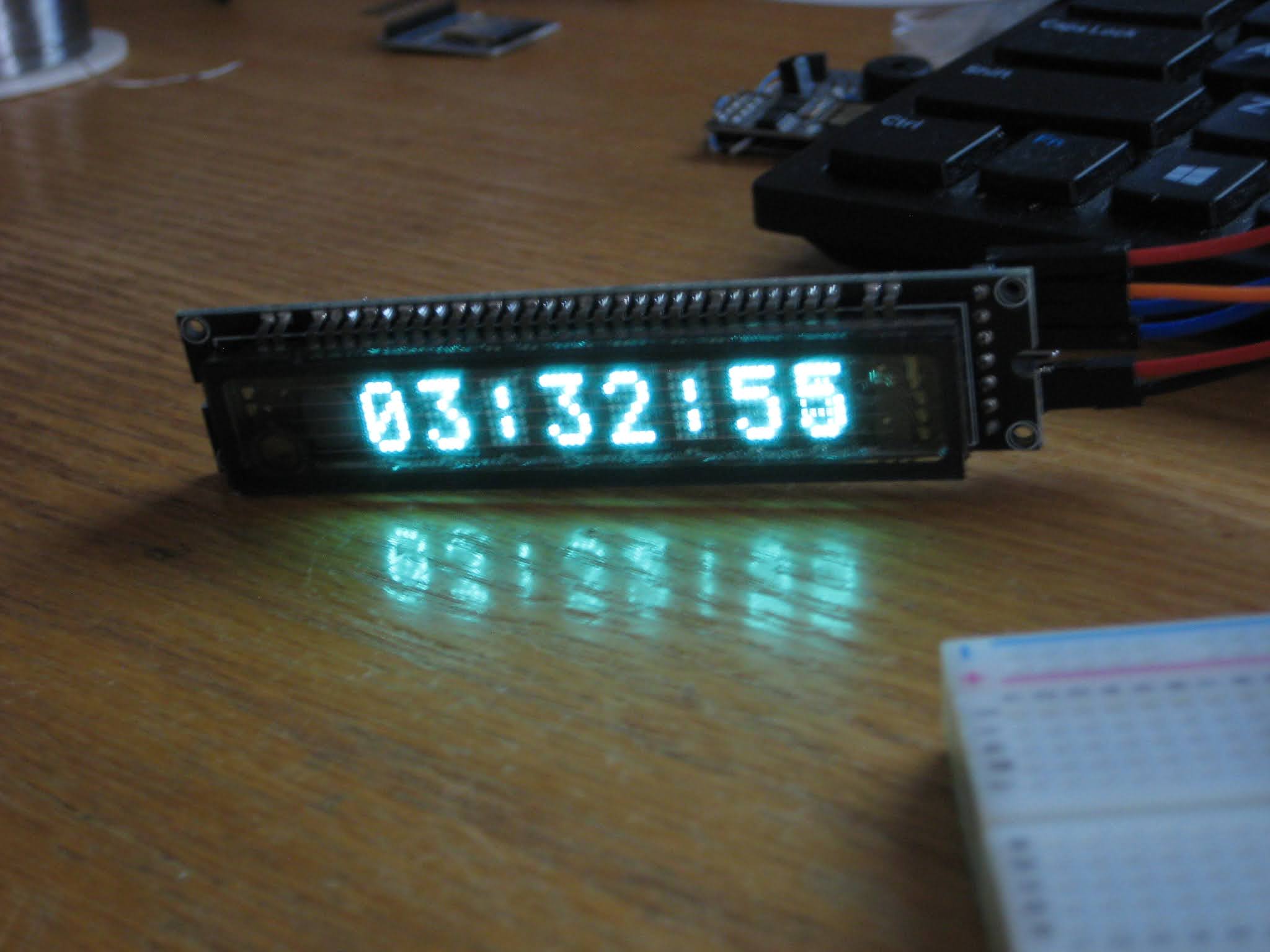
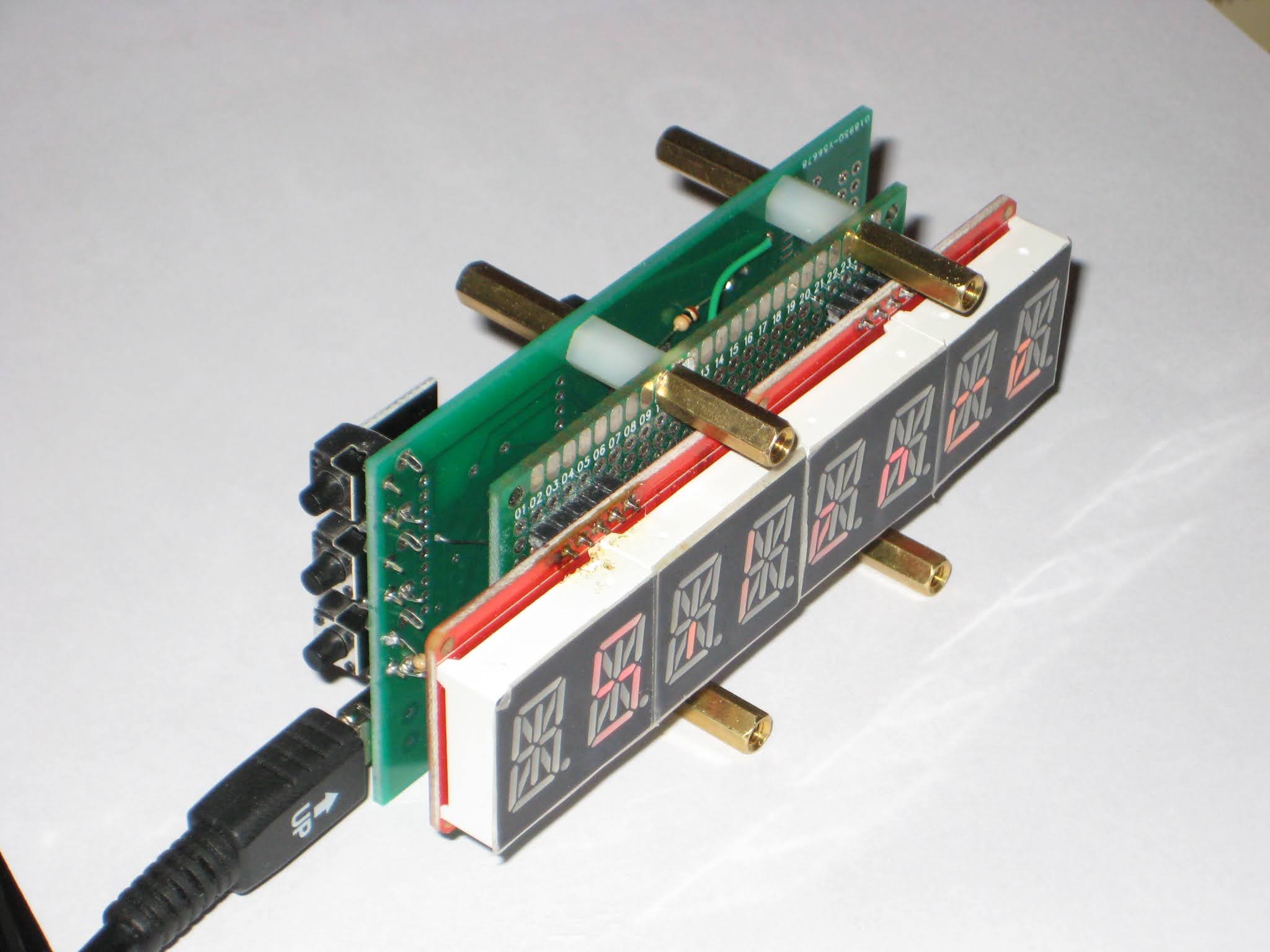
It has an SPI interface, it is powered by 5V, character set is defined and stored internally.

A quick search produced a sketch and documentation for the driver, PT6302.

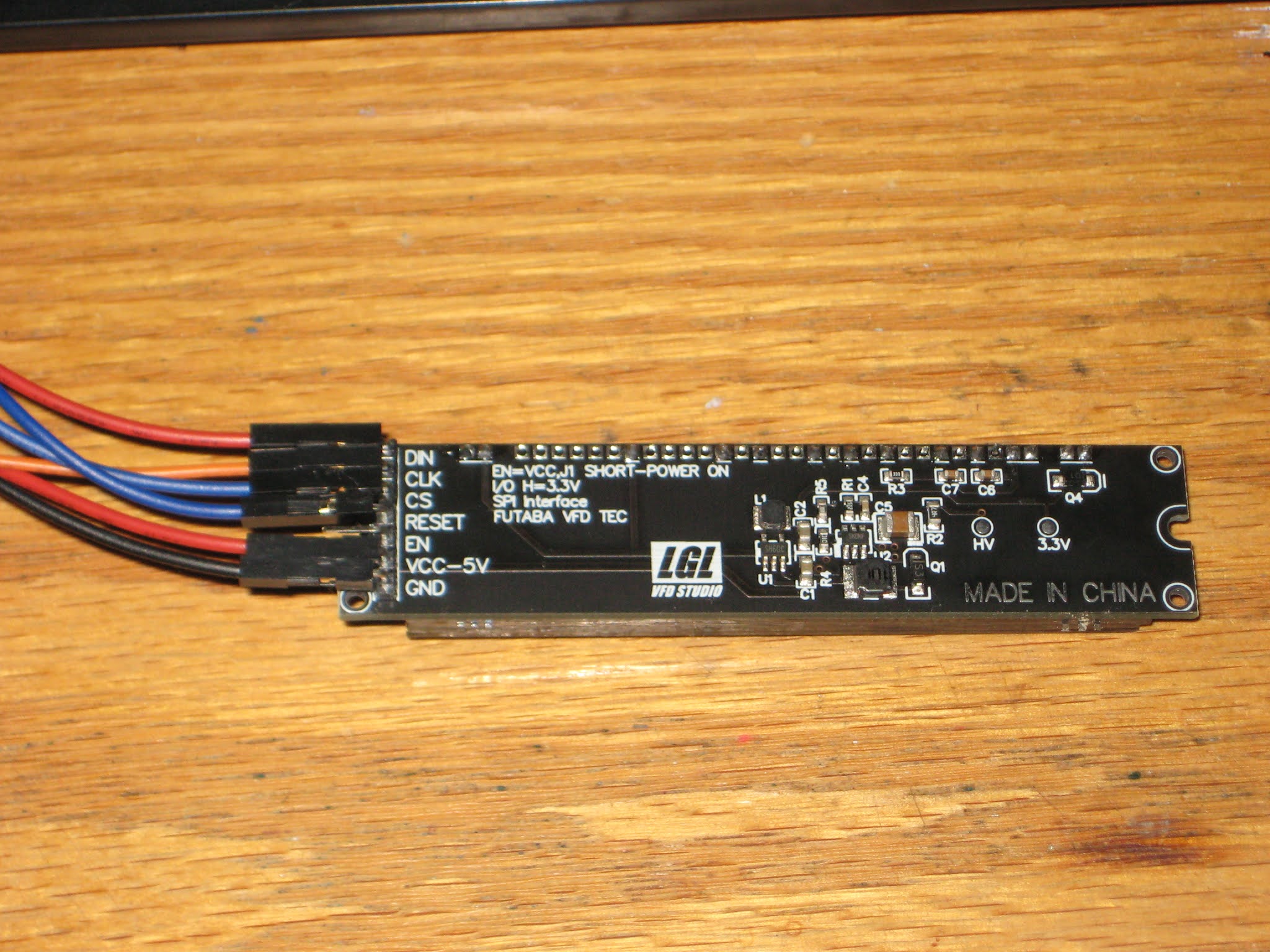
According to the PCB silkscreen, the VFD module is powered by 5V, but the signals are 3V3. (The 30V required by the VFD glass itself is made by the on-board switching mode power supply, so no need to worry about generating high voltage externally.) An ESP32 board would be the perfect candidate to control this display. Luckily, the found sketch was also written for ESP32, so all I had to do was compile and upload using Arduino IDE 1.8.13. The only problem was that my IDE installation did not show ESP32 boards anymore, even though I used it once previously. Therefore, I had to re-visit the whole setup process once again. This time I am documenting it, to save on any future effort. So here are the steps:

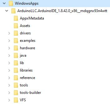
  • install Arduino IDE (1.8.13, in my case) from Windows store, placed here:

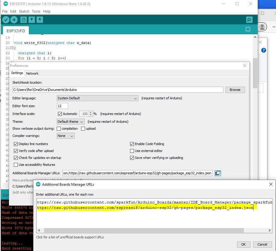
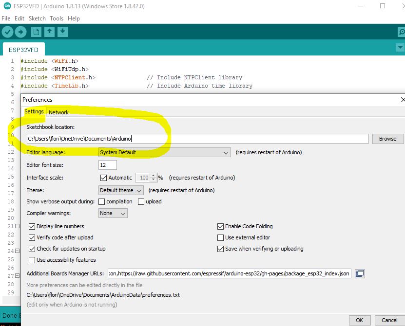
  • add the ESP32/expressif package URL for the Boards Manager, as nicely explained here; essentially, select menu File -> Preferences, then add line
https://raw.githubusercontent.com/espressif/arduino-esp32/gh-pages/package_esp32_index.json
to input box "Additional Boards Manager URLs".
  • install the set of ESP32 boards in "Boards Manager"; menu Tools -> Boards Manager:
  • select the proper board for the ESP32-WROOM dev kit that I used; menu Tools -> Boards Manager -> ESP32 Arduino -> Node32s;
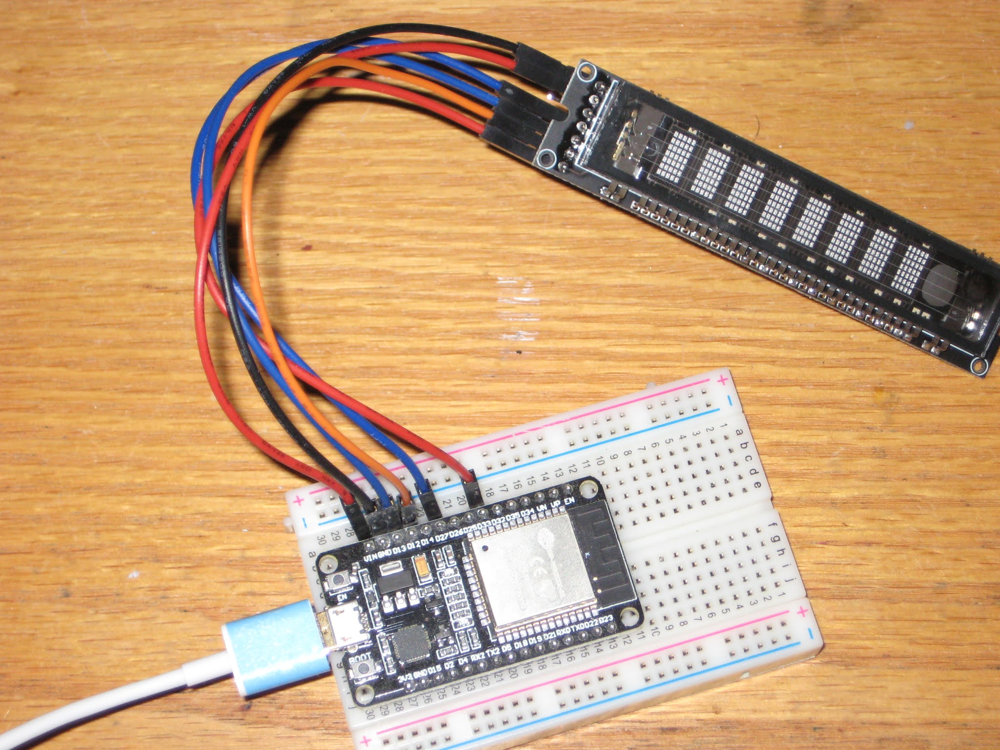
  • open the sketch, then modify the SPI pins (I used DIN=33, CLK=12, CS=13, RST=27, all on the same side of the ESP32 dev module); got compilation error "Library not found" for both NTPClient and TimeLib;
  • install the missing libraries, through menu Tools -> Manage Libraries...
The 2 libraries have been installed here
at the location specified in File -> Preferences:
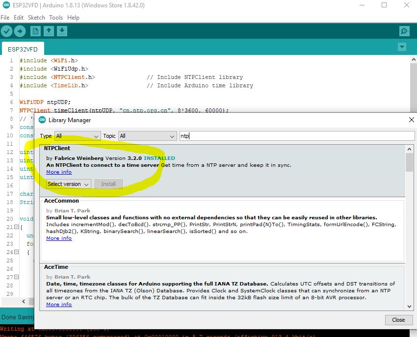
  • compile, then upload successfully.
Surprisingly easy, straightforward and without glitches, this must have been the easiest ever first-time  interfacing with a device.

Compared to the HDSP-2534 LED display, the characters in the VFD module are about 50% bigger, and much brighter, making it readable from a greater distance. The current consumption is in the range 100-200mA, versus about 20mA taken by the HDSP display.


Also, at just about US$13, this (yet unnamed, or maybe Futaba?, see photo below) VFD display makes a great functional alternative for the more expensive HDSP/Avago/Siemens/Osram 8-character LED displays.


For the record, this was my setup:


And the (modified, barebone) sketch:
#include <WiFi.h>
#include <WiFiUdp.h>
#include <NTPClient.h>
#include <TimeLib.h>

WiFiUDP ntpUDP;
NTPClient timeClient(ntpUDP, "cn.ntp.org.cn", 8*3600, 60000);
const char *ssid = "<wifinet>";
const char *password = "<password>";

uint8_t din = 33; // DA
uint8_t clk = 12; //23; // CK
uint8_t cs = 13; //19; // CS
uint8_t Reset = 27; //22; // RS

char *str_time = "00:00:00";
String format_time = "00:00:00";

void write_6302(unsigned char w_data)
{
unsigned char i;
for (i = 0; i < 8; i++)
{
digitalWrite(clk, LOW);
if ( (w_data & 0x01) == 0x01)
{
digitalWrite(din, HIGH);
}
else
{
digitalWrite(din, LOW);
}
w_data >>= 1;
digitalWrite(clk, HIGH);
}
}

void VFD_cmd(unsigned char command)
{
digitalWrite(cs, LOW);
write_6302(command);
digitalWrite(cs, HIGH);
delayMicroseconds(5);
}

void S1201_show(void)
{
digitalWrite(cs, LOW);
write_6302(0xe8);
digitalWrite(cs, HIGH);
}

void VFD_init()
{
// set number of characters for display;
digitalWrite(cs, LOW);
write_6302(0xe0);
delayMicroseconds(5);
write_6302(0x07); // 8 chars;
digitalWrite(cs, HIGH);
delayMicroseconds(5);

// set brightness;
digitalWrite(cs, LOW);
write_6302(0xe4);
delayMicroseconds(5);
write_6302(0x33); // level 255 (max);
digitalWrite(cs, HIGH);
delayMicroseconds(5);
}

void S1201_WriteOneChar(unsigned char x, unsigned char chr)
{
digitalWrite(cs, LOW);
write_6302(0x20 + x);
write_6302(chr + 0x30);
digitalWrite(cs, HIGH);
S1201_show();
}

void S1201_WriteStr(unsigned char x, char *str)
{
digitalWrite(cs, LOW);
write_6302(0x20 + x);
while (*str)
{
write_6302(*str); // ascii
str++;
}
digitalWrite(cs, HIGH);
S1201_show();
}

void setup()
{
WiFi.begin(ssid, password);
Serial.begin(115200);
Serial.print("Connecting.");
while ( WiFi.status() != WL_CONNECTED ) {
delay(500);
Serial.print(".");
}
Serial.println("connected");

timeClient.begin();

pinMode(clk, OUTPUT);
pinMode(din, OUTPUT);
pinMode(cs, OUTPUT);
pinMode(Reset, OUTPUT);
digitalWrite(Reset, LOW);
delayMicroseconds(5);
digitalWrite(Reset, HIGH);
VFD_init();
}

void loop()
{
timeClient.update();
format_time = timeClient.getFormattedTime();
char *str_time = &format_time[0];
S1201_WriteStr(0, str_time);
Serial.println(timeClient.getFormattedTime());
delay(1000);
}


Next step should be researching the PT6302 command set, finding out how to adjust brightness and others.


Biggest WiFiChron display so far

In the world of 16-segment displays, Klais-16 is the biggest I have seen, at about 8cm (3") character height. Multiple displays can be daisy-chained and controlled through serial communication (1 pin, TX). It is open source and available to buy on Tindie at the very reasonable price of US$15 a piece.

The biggest challenge was mechanical, particularly, finding a way to mount the 8 individual displays. Let me explain. I received the displays as ready-to-use (assembled, programmed and tested) products. I did  not expected to dis-assemble them (not even partially) in order to mount them. The two mounting methods described in the documentation (using 15mm and 20mm profiles, respectively) ask for just that, basically to cut the original plastic rivets and, eventually, to replace them with (your own) M3 screws when fixing them to the rails. (I actually started going along with either described method until I realized I did not want to open them up). The easiest solution I found in the end was to use 1/2" x 1/2" L-profile, as shown below. For this, I only cut the middle rivets and used the holes to screw each individual display to the rails.


The software support consists in adding one class, DisplaySoftSerial.cpp, shown below.

#include <Arduino.h>
#include <SoftwareSerial.h>
#include "DisplaySoftSerial.h"

SoftwareSerial ss(7, 2); // RX not used; TX=2;

//******************************************************************
//
void Display_t::setup()
{
ss.begin(19200);
}

//******************************************************************
// draw the 8 characters on the screen;
//
void Display_t::writeDisplay(char* displayBuffer)
{
char reverseBuffer[9] = {0};

for (byte i=0; i<9; i++)
{
reverseBuffer[i] = (displayBuffer[7-i]);
}
ss.write(reverseBuffer);
}

//*******************************************************************
// brightness level is number between 0 and 7, 0 being the brightest;
//
void Display_t::setBrightness(uint8_t brightness)
{
// cannot do;
}

//*******************************************************************
//
void Display_t::reset()
{
}


The Klais-16 display's baud rate can be selected in the range 4800 to 115200, through solder jumpers. The default (no soldering) is 115200. I set it to 19200 because:
  • SoftwareSerial library cannot handle 115200
  • only one solder bridge is required
As you can see from the code above, the brightness cannot be adjusted (or at least I am not aware). Maybe future versions will implement this feature.

The WiFiChron with the 8 Klais-16 displays consumes an average of 700mA (at 5V). The brightness is not amazing, probably because some of the light is absorbed by the top translucent PCB.
I think it can make a great clock for interiors (schools, hallways etc.), visible from at least 10 meters away.


Enclosure ideas for WiFiChron and other clocks

It turns out that most electronics, even prototypes, can be easily enclosed with Lego. And that means no screws, no glue, no fasteners, zero tools, just the bricks and some imagination.

This is the HDSP clock variant with 1" displays driven by HT16K33 (introduced here). The board was cut and filed (0.5mm on each side) to fit snug between the walls (see this).


Next is a HDSP clock variant with two Adafruit Quad Alphanumeric displays.


Similarly, the PCB was cut and filed a bit. The assembly fits solidly between the bricks (no movement when shaken). As in the previous build, the exposed PCB is kind-of-required to allow access to the two buttons (set hours, set minutes).

Both of the above can be mounted on a Lego wall (as found in schools) or they can desk-stand on their own.

Here is an example of a Lego-encapsulated WifiChron.


The PCB was also filed about 0.5mm on each side to fit between the lateral brick walls. It did not have to be fastened in any other way. The ESP8266 module fits inside nicely. The 3 buttons and the USB mini B connector are all easily accessible from the back.

Below is the Lego version of the Axiris clock.


Since it does not have any buttons, the time is set through Bluetooth (command "SET TIME=hh:mm", sent from Terminal app while BT paired).

And finally, a couple of OLED clocks, both running the same software on similar hardware: pro-mini + OLED shield and wsduino + 2.42" OLED shield, respectively.


Note that this is the prototype version, using a LiPo battery with charger (similar to the one shown here).


Again, all the above enclosures feel solid: nothing moves or rattles when upside down or even shaken. I did not try dropping them though :)

And lastly, the WiFiChron with Adafruit quad 0.56" displays from the previous post, sandwiched between scrap plexiglass plates:


More WiFiChron variants

This post shows two WiFiChron mods, that look more like finished projects rather than just experiments.

First one uses the WiFiChron board connected on I2C to two Adafruit Quad Alphanumeric Displays (I2C addresses 0x70 and 0x71). The WiFiChron software has similar adaptation as the one for HDSP clock (see this post for details).


Did I mention that two plexiglass plates are still waiting to be cut and screwed in the standoffs?

This (poor) video shows it in action.

The interesting thing about the Chinese clones (of the Adafruit displays) I had in hand is that each module has one (2 digit) display red and the other orange. Initially I thought it's a manufacturing error, but after checking, it seems that this is intended (for reasons I do not understand).

The second one is an "HDSP clock" with a 8-character display with 16-segment LED modules, introduced here, cased in a LEGO enclosure.

After cutting the top of board off (since there is no HDSP-2534) and a little filing of all sides, the PCB fit perfectly between the LEGO bricks.


For this display, the line that has to be enabled (un-commented) in DAL.h is:

#define DISPLAY_HT16K33


Alternative displays for HDSP or WiFiChron clocks

So you would like to build your own HDSP clock or WiFiChron clock but you find the HDSP-2534 display too small or too expensive. Why not just replace it with a bigger 8-character display, like the 1-inch 8 x 16-segment or two cascaded Adafruit 0.54" 4 x 14-segment backpacks? We have you covered, in software. Both these displays are now supported, as extension classes of the DAL (Display Abstraction Layer), together with the 128x64 I2C OLED and the HT1632-based 32x8 LED matrix display (used to be from Sure  Electronics). Support could be further extended to LCD displays (think big font on 40x4), MAX6955 with 8 x 16 segment etc., basically anything that can show 8 alphanumeric characters (numbers only, like regular Nixie tubes, would not suffice).

Below are some examples.

Two Adafruit 4-character backpacks are connected on I2C, addresses 0x70 (default) and 0x71, handled by class DisplayAda14seg, which in turn uses the Adafruit_LEDBackpack library.


To enable this display, uncomment the line (in DAL.h, comment out the rest):
#define DISPLAY_ADA_14SEG  // 2 x Adafruit 4x14seg displays;

Functionality for the 8x32 (or 16x32) LED matrix display is implemented in class DisplayHT1632, which is based on code recycled from Wise Clock 4. To enable this display, simply uncomment the line (in DAL.h, comment out the others):
#define DISPLAY_HT1632	 // Sure 8x32 LED matrix controlled by HT1632;


To accommodate the 8 characters on a 32-pixel line, fontTiny had to be used (each character is 4 pixels wide).

Note the connections for the HT1632 display (in DisplayHT1632.cpp):
#define HT1632_DATA 4 // Data pin (pin 7 of display connector)
#define HT1632_CS         3      // Chip Select (pin 1 of display connnector)
#define HT1632_WRCLK 2 // Write clock pin (pin 5 of display connector)
#define HT1632_CLK 5 // clock pin (pin 2 of display connector)

Other possible definitions in DAL.h are:
//****************************************************************************************
// Define the display you wish to use here.
// Comment out the ones not used.

//#define DISPLAY_HDSP2534 // original HDSP-2534 display in HDSP clock;
//#define DISPLAY_HUB08 // TODO: 8x32 LED matrix display with cascading shift registers (?)
//#define DISPLAY_DL1414 // 2 x DL1414; tested June 23, 2018 (http://timewitharduino.blogspot.com/2018/06/wifichron-adapter-for-dl-1414-displays.html)
//#define DISPLAY_HT16K33 // my 8x16-segment driven by HK16K33, tested Jul 26, 2020;
//#define DISPLAY_OLED // I2C OLED; tested
#define DISPLAY_HT1632 // Sure 8x32 LED matrix controlled by HT1632; tested Aug 14, 2020;
//#define DISPLAY_MAX6955 // TODO: 8x16 segment driven by MAX6955
//#define DISPLAY_LCD1602 // TODO: classic LCD 16x2 (or better 40x4, with big font);
//#define DISPLAY_ADA_14SEG // 2 x Adafruit 4x14seg displays, wired on 0x70 and 0x71 I2C addresses; tested Jul 26, 2020;

// show time on the 60-pixel Adafruit Neopixel ring;
//#define _ADD_NEOPIXEL_
//****************************************************************************************


And so on.


Alternative displays for HDSP or WiFiChron clocks

So you would like to build your own HDSP clock or WiFiChron clock but you find the HDSP-2534 display too small or too expensive. Why not just replace it with a bigger 8-character display, like the 1-inch 8 x 16-segment or two cascaded Adafruit 0.54" 4 x 14-segment backpacks? We have you covered, in software. Both these displays are now supported, as extension classes of the DAL (Display Abstraction Layer), together with the 128x64 I2C OLED and the HT1632-based 32x8 LED matrix display (used to be from Sure  Electronics). Support could be further extended to LCD displays (think big font on 40x4), MAX6955 with 6x16 segment etc., basically anything that can show 8 alphanumeric characters (numbers only, like regular Nixie tubes, would not suffice).

Below are some examples.

Two Adafruit 4-character backpacks are connected on I2C, addresses 0x70 (default) and 0x71, handled by class DisplayAda14seg, which in turn uses the Adafruit_LEDBackpack library.


To enable this display, uncomment the line (in DAL.h, comment out the rest):
#define DISPLAY_ADA_14SEG  // 2 x Adafruit 4x14seg displays;

Functionality for the 8x32 (or 16x32) LED matrix display is implemented in class DisplayHT1632, which is based on code recycled from Wise Clock 4. To enable this display, simply uncomment the line (in DAL.h, comment out the others):
#define DISPLAY_HT1632	 // Sure 8x32 LED matrix controlled by HT1632;


To accommodate the 8 characters on a 32-pixel line, fontTiny had to be used (each character is 4 pixels wide).

Other possible definitions in DAL.h are:
//****************************************************************************************
// Define the display you wish to use here.
// Comment out the ones not used.

//#define DISPLAY_HDSP2534 // original HDSP-2534 display in HDSP clock;
//#define DISPLAY_HUB08 // TODO: 8x32 LED matrix display with cascading shift registers (?)
//#define DISPLAY_DL1414 // 2 x DL1414; tested June 23, 2018 (http://timewitharduino.blogspot.com/2018/06/wifichron-adapter-for-dl-1414-displays.html)
//#define DISPLAY_HT16K33 // my 8x16-segment driven by HK16K33, tested Jul 26, 2020;
//#define DISPLAY_OLED // I2C OLED; tested
#define DISPLAY_HT1632 // Sure 8x32 LED matrix controlled by HT1632; tested Aug 14, 2020;
//#define DISPLAY_MAX6955 // TODO: 8x16 segment driven by MAX6955
//#define DISPLAY_LCD1602 // TODO: classic LCD 16x2 (or better 40x4, with big font);
//#define DISPLAY_ADA_14SEG // 2 x Adafruit 4x14seg displays, wired on 0x70 and 0x71 I2C addresses; tested Jul 26, 2020;

// show time on the 60-pixel Adafruit Neopixel ring;
//#define _ADD_NEOPIXEL_
//****************************************************************************************


And so on.


Clock super-display

Today was a good day. In typical fashion, I started a few new "projects" almost in the same time. First one, it's assembling of a new kind of clock, from a kit sent by Nick S. I got stuck pretty early though, so I "parked" it for now. Details to come soon, in a special post.

Second one, an "Adler 121PD" vintage calculator with a VFD display, that I found "in the dumpster" (well, not really, but the idea is the same, I got it for free). I was going to break it apart, for the display and the circuitry, but I gave up when I powered it up (with an improvised cable; the original, proprietary one, was missing) and it actually worked! I may still go ahead with dis-assembling it, since it is not a great value anyway; I checked prices on ebay, and they go for around $20.

Lastly, the project that gave the name of this post: a clock LED super-display, consisting of 3 individual and independent indicators, inspired by the Leitch studio clock, brought to my attention by Nick (VE2HOT). The goal for the clock super-display is to eventually be able to emulate the Leitch clock. Here it is, in its incipient glory (only the back panel; the black wooden frame not pictured):


Since I am not the crafty kind-of-guy (also not keen on spending for form more than for content), I am always looking for cheap, easy and quick solutions for encasing electronics. In this case, Ikea's Ribba 9"x9" frame ($10) seems to be a good fit for the job, and hopefully will help the future clock look "Leitchy" or even better (Nick's photo below):


The 2 alphanumeric displays (4 and 8 chars) of the clock super-display are I2C-driven. The 60 LED ring is adafruit neopixel, controlled by a single output pin. With this setup, even an ESP8266 module could be used as the brains of the clock.

The ring is fixed to the cardboard back/panel of the deep Ikea frame with four M3 plastic standoffs glued to the PCB.
The 4-character alphanumeric 16-segment is my creation, introduced earlier. It is driven by the HT16K33 backpack, also from adafruit (not in the picture). The PCB has M3 holes for screws.
The 8-character alphanumeric is made of two side-by-side quad 14-segment LED displays, also from adafruit. The 2 modules already have the HT16K33 drivers installed (soldered on the back). Attaching these quad displays to the panel is not easy, since the holes are probably M1.4. Even these thin M1.4 screws need to be forced, because the screw head presses against display's plastic enclosure. Eventually, the M1.4 screws will be glued to the M3 plastic standoffs, that's the best I could come up with. It is weird that, for such a popular and successful product, one cannot find photos (or instructions) on mounting these modules using screws.

Next step is the software support in the WiFiChron software. Also need to find a way to access the 3 buttons: having them in the back is not a good idea, having them in the front is impossible, unless the glass is replaced with transparent/smoky/grey acrylic, which can be drilled.

Wise time with Arduino 11 May 02:13
esp8266  hdsp  i2c  wifichron  

Clock super-display

Today was a good day. In typical fashion, I started a few new "projects" almost in the same time. First one, it's assembling of a new kind of clock, from a kit sent by Nick S. I got stuck pretty early though, so I "parked" it for now. Details to come soon, in a special post.

Second one, an "Adler 121PD" vintage calculator with a VFD display, that I found "in the dumpster" (well, not really, but the idea is the same, I got it for free). I was going to break it apart, for the display and the circuitry, but I gave up when I powered it up (with an improvised cable; the original, proprietary one, was missing) and it actually worked! I may still go ahead with dis-assembling it, since it is not a great value anyway; I checked prices on ebay, and they go for around $20.

Lastly, the project that gave the name of this post: a clock LED super-display, consisting of 3 individual and independent indicators, inspired by the Leitch studio clock, brought to my attention by Nick (VE2HOT). The goal for the clock super-display is to eventually be able to emulate the Leitch clock. Here it is, in its incipient glory (only the back panel; the black wooden frame not pictured):


Since I am not the crafty kind-of-guy (also not keen on spending for form more than for content), I am always looking for cheap, easy and quick solutions for encasing electronics. In this case, Ikea's Ribba 9"x9" frame ($10) seems to be a good fit for the job, and hopefully will help the future clock look "Leitchy" or even better (Nick's photo below):


The 2 alphanumeric displays (4 and 8 chars) of the clock super-display are I2C-driven. The 60 LED ring is adafruit neopixel, controlled by a single pin. With this setup, even an ESP8266 module could be used as the brains of the clock.

The ring is fixed to the cardboard back/panel of the deep Ikea frame with four M3 plastic standoffs glued to the PCB.
The 4-character alphanumeric 16-segment is my creation, introduced earlier. It is driven by the HT16K33 backpack, also from adafruit (not in the picture). The PCB has M3 holes for screws.
The 8-character alphanumeric is made of two side-by-side quad 14-segment LED displays, also from adafruit. The 2 modules already have the HT16K33 drivers installed (soldered on the back). Attaching these quad displays to the panel is not easy, since the holes are probably M1.4. Even these thin M1.4 screws need to be forced, because the screw head presses against display's plastic enclosure. Eventually, the M1.4 screws will be glued to the M3 plastic standoffs, that's the best I could come up with. It is weird that, for such a popular and successful product, one cannot find photos (or instructions) on mounting these modules using screws.

Next step is the software support in the WiFiChron software. Also need to find a way to access the 3 buttons: having them in the back is not a good idea, having them in the front is impossible, unless the glass is replaced with transparent/smoky/grey acrylic, which can be drilled.

Wise time with Arduino 11 May 02:13
esp8266  hdsp  i2c  wifichron  

WiFiChron support for 16-segment LED display

This is the second time I am writing this post. First time it just disappeared after almost 2 hours of editing. I started the post by saying that whenever I want to have some electronics fun, I open one of my drawers. Nice story line, but I am too frustrated now to recreate it from memory. (The lesson I learned is that I should write it first as a document, save locally, then copy and paste into a blog post.)
So I will keep it short and dry.

Some time ago, I designed this "4-character 16-segment 1-inch LED" board (pictured below), briefly mentioned here. I abandoned it, after a couple of failed tries, while writing the character definitions. Since then, I discovered the Adafruit 4-char alphanumeric LED backpack, which comes with nice software support as well.


For WiFiChron, two cascaded modules make an 8-character display functionally similar to HDSP-2534, but bigger and more visible. With the "Display Abstraction Layer" already in place, software support should be easy to integrate, since controlling it with the HT16K33 breakout allows the re-use of the above mentioned Adafruit LED backpack library. For maximum compatibility, I followed the same wiring, then connected the two extra segments, A2 and D2, to pin 10 (not connected for the 14-segment backpack) and pin 11 (connected to the DP), respectively.


I added a new class, Alphanum8x16, to the original files (Adafruit_LEDBackpack.h and cpp) to control the extra segments:


class Alphanum8x16 : public Adafruit_AlphaNum4
{
 public:
  void writeDigitAscii(uint8_t n, uint8_t ascii);
};


void Alphanum8x16::writeDigitAscii(uint8_t n, uint8_t a)
{
  uint16_t font = pgm_read_word(alphafonttable+a);
  displaybuffer[n] = font;

  //--------------------------------------------------------
  // this is the Adafruit mapping of digits to segments:
  // 0 DP N M L K J H G2 G1 F E D C B A
  //
  // this is the 16 seg mapping of digits to segments:
  // A2 D2 N M L K J H G2 G1 F E D1 C B A1
  //
  // bits:
  // 1  1  1 ...                 ...  1 0
  // 5  4  3
  //
  // Note: DP is not connected/controlled for the 16 seg;
  //--------------------------------------------------------

  // if A1 (bit 0) is on, set A2 (bit 15) as well;
  if (font & 1)
    displaybuffer[n] |= 0x8000;

  // if D1 (bit 3) is on, set D2 (bit 14) as well;
  if (font & 8)
    displaybuffer[n] |= 0x4000;
}

The 8x16-segment display is implemented in class DisplayHT16K33 in the WiFiChron software.
So far, WiFiChron can support the following displays (defines in DAL.h):

//#define DISPLAY_HDSP2534
//#define DISPLAY_DL1414
#define DISPLAY_HT16K33
//#define DISPLAY_OLED
//#define DISPLAY_HT1632
//#define DISPLAY_MAX6955

In principle, any display that can show 8 characters can be used through DAL.


Wise time with Arduino 14 Apr 02:15
hacking  hdsp  i2c  wifichron