There’s much truth in the advice that, to truly understand something, you need to build it yourself from the ground up. That’s the idea behind [Christian]’s entry for the Re-engineering Education category of the 2023 Hackaday Prize. Built as an educational demonstrator, this is a complete arithmetic-logic unit (ALU) using discrete relays — and not high-density types either — these are the big honking clear-cased kind.
The design is neatly, intentionally, partitioned along functional lines, with four custom PCB designs, each board operating on 4-bits. To handle a byte-length word, boards are simply cascaded, making a total of eight. The register, adder, logic function, and multiplex boards are the heart of the build with an additional two custom boards for visualization (using an Arduino for convenience) and IO forming the interface. After all, a basic CPU is just an ALU and some control around it, the magic is really in the ALU.
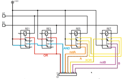
The fundamental logical operations operating upon two operands, {A, B} are A, ~A, B, ~B, A or B, A and B, A xor B, can be computed from just four relays per bit. The logic outputs do need to be fed into a 7-to-1 bit selector before being fed to the output register, but that’s the job of a separate board. The adder function is the most basic, simply a pair of half-adders and an OR-gate to handle the chaining of the carry inputs and generate the carry chain output.
3D printed cable runs are a nice touch and make for a slick wiring job to tie it all together.
This thing has what plants crave! No, not electrolytes exactly — just water, light, and moisture polling every 30 minutes. We think it’s fitting to take something that once manufactured liquid liveliness for humans and turn it into a smart garden that does the same thing for plants.
So let’s just get this out of the way: the espresso machine was abandoned because it was leaking water from a gasket. [The Plant Bot] cleaned it up, replaced the gasket, and got it brewing, and then it started leaking hot water again from the same gasket. We might have gone Office Space on this beautiful machine at that point, but not [The Plant Bot].
Down in the dirt, there’s a soil moisture sensor that’s polling every 30 minutes. If the moisture level falls below the threshold set appropriately at a life-sustaining 42%, the Arduino is triggered to water the plant through a relay board using the espresso machine’s original pump. If the plant is dry, the machine will pump water for two seconds every minute until the threshold is met. [The Plant Bot] tied it all together with a nice web interface that shows plant data and allows for changes over Bluetooth.
[The Plant Bot] started by disconnecting the heating element, because plants don’t tend to like hot steam. But if the cup warming tray along the top has a separate heating element, it might be neat to reuse it for something like growing mushrooms, or maintaining a sourdough starter if the temperature is right.
It’s a problem common to every hackerspace, university machine shop, or even the home shops of parents with serious control issues: how do you make sure that only trained personnel are running the machines? There are all kinds of ways to tackle the problem, but why not throw a little tech at it with something like this magnetic card-reader machine lockout?
[OnyxEpoch] does not reveal which of the above categories he falls into, if any, but we’ll go out on a limb and guess that it’s a hackerspace because it would work really well in such an environment. Built into a sturdy steel enclosure, the guts are pretty simple — an Arduino Uno with shields for USB, an SD card, and a data logger, along with an LCD display and various buttons and switches. The heart of the thing is a USB magnetic card reader, mounted to the front of the enclosure.
To unlock the machine, a user swipes his or her card, and if an administrator has previously added them to the list, a relay powers the tool up. There’s a key switch for local override, of course, and an administrative mode for programming at the point of use. Tool use is logged by date, time, and user, which should make it easy to identify mess-makers and other scofflaws.
We find it impressively complete, but imagine having a session timeout in the middle of a machine operation would be annoying at the least, and potentially dangerous at worst. Maybe the solution is a very visible alert as the timeout approaches — a cherry top would do the trick!
It’s been said that the best way to tackle the issue of childhood obesity would be to hook those children’s video game consoles up to a pedal-powered generator. Of course, this was said by [Alex], the creator of Cykill. Cykill interfaces an Xbox to an exercise bike, so to keep the video game going you’ll have to keep pedaling the bike.
While there is no generator involved in this project, it does mimic the effect of powering electronics from a one. The exercise bike has a set of communications wires, which are connected to a relay on the Xbox’s power plug. When the relay notices that the bike isn’t being pedaled enough, it automatically cuts power to the console. Of course, the risk of corrupting a hard drive is high with this method, but that only serves to increase the motivation to continue pedaling.
The project goes even further in order to eliminate temptation to bypass the bike. [Alex] super-glued the plug of the Xbox to the relay, making it extremely difficult to get around the exercise requirement. If you’re after usable energy instead of a daily workout, though, there are bikes out there that can power just about any piece of machinery you can imagine.
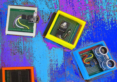
In this tutorial, I will be evaluating Prextron CHAIN blocks – a new system that allows you to connect your sensors and actuators to an Arduino NANO using clever 3D-printed prototyping boards that can be stacked sideways. This very modular system makes it easy to connect, disconnect and replace project components, and eliminate the “rats nest of wires” common to many advanced Arduino projects. CHAIN BLOCKS are open, which means that you can incorporate any of your sensors or actuators to these prototyping boards, and you can decide which specific pin on Arduino you plan to use. The CHAIN BLOCK connections prevent or reduce common connection mistakes, which make them ideal for class-room projects and learning activities.
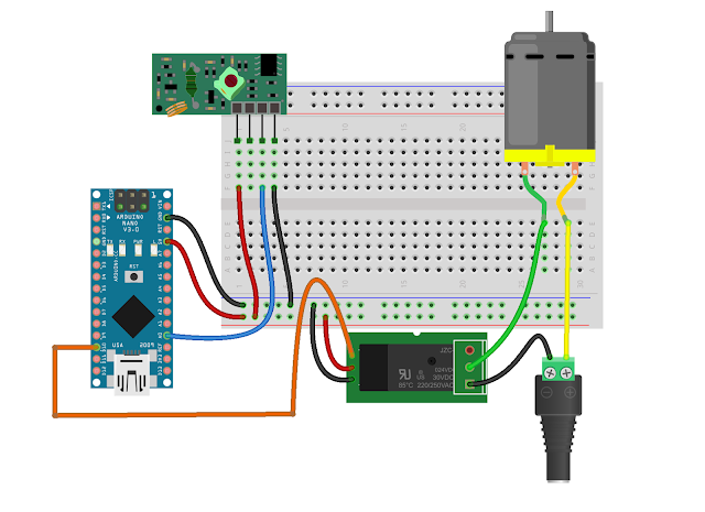
I am going to set up a project to put these CHAIN BLOCKs to the test: When I place my hand in-front of an Ultrasonic sensor, the Arduino will transmit a signal wirelessly to another Arduino, and consequently turn on a motor.
Please note: You may need to solder the module wires to the CHAIN BLOCK protoboard.
Arduino Libraries and IDE
This project does not use any libraries. However, you will need to upload Arduino code to the Arduino. For this you will need the Arduino IDE which can be obtained from the official Arduino website: https://www.arduino.cc/en/main/software
ARDUINO CODE: RF Transmitter
ARDUINO CODE: RF Receiver
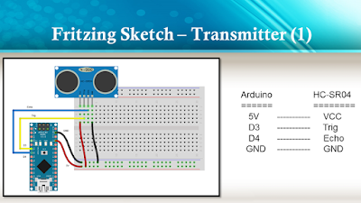
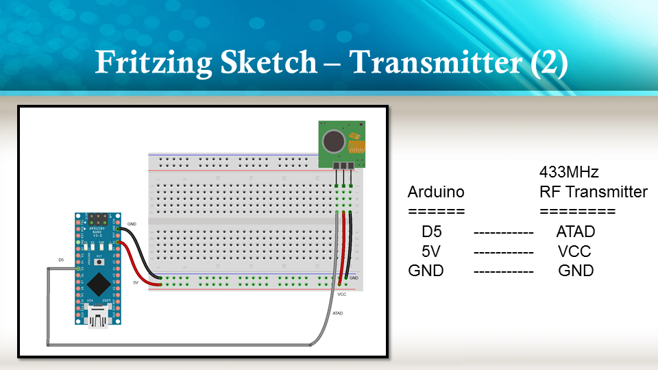
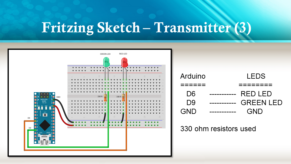
Fritzing diagrams for Transmitter
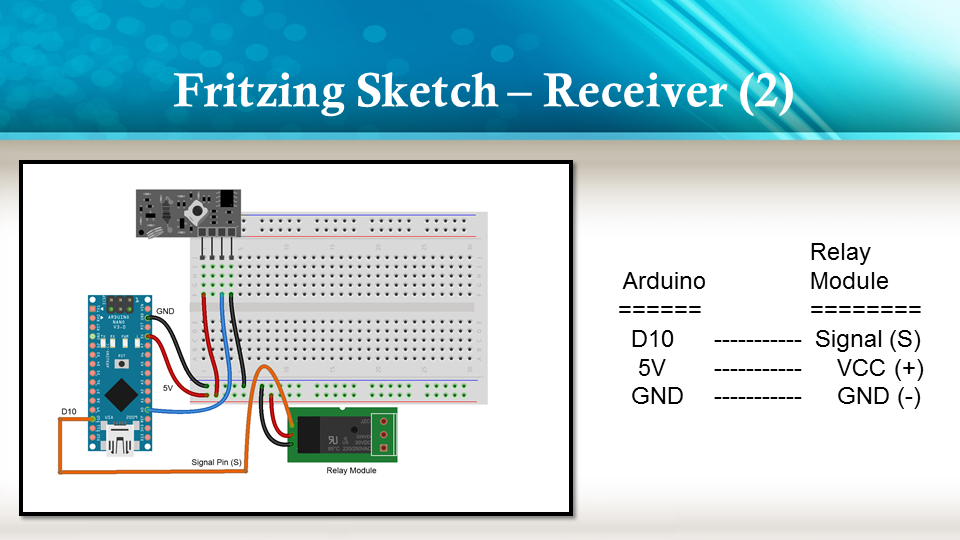
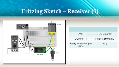
Fritzing diagrams for Receiver
Concluding comments
The purpose of this project was to evaluate Prextron CHAIN BLOCKs and put them to the test. Here is what I thought of CHAIN BLOCKS at the time of evaluation. Some of my points mentioned below may no longer apply to the current product. It may have evolved / improved since then. So please take that into consideration
What I liked about Chain Blocks
The design is simple, the product is simple.
Once the Chain Blocks were all assembled, they were very easy to connect to each other.
I can really see the benefit of Chain Blocks in a teaching environment, because it simplifies the connection process, and reduces connection mixups.
It was good to see that the blocks come in different colours, which means that you can set up different colour schemes for different types of modules.
You can incorporate pretty much any sensor or Actuator into the Chain block which is very appealing.
You also have the flexibility of choosing which pins you plan to use on the Arduino.
Projects look a lot neater, because you no longer have the rats nest of wires.
The Blocks lock into each other which means that they are much easier to transport/carry.
What I did not like about Chain Blocks
In most cases, the Chain Block protoboard lanes were not numbered, which increased the chances of making mistakes when soldering
The need to solder modules to the protoboard, may be a discouragement for some people.
I would have liked a choice of different size Chain blocks. Some of the sensors did not fit nicely into the Square blocks.
Prextron really need to work on their website if they plan to get serious with this product: Webpage has incomplete functionality or irrelevant links etc etc.
Thank you very much to Prextron for providing the CHAIN BLOCKS used in this tutorial, and allowing me to try out their product. If you are interested in trying them yourself, then make sure to visit them at:
If you like this page, please do me a favour and show your appreciation :
In this tutorial, I will be evaluating Prextron CHAIN blocks – a new system that allows you to connect your sensors and actuators to an Arduino NANO using clever 3D-printed prototyping boards that can be stacked sideways. This very modular system makes it easy to connect, disconnect and replace project components, and eliminate the “rats nest of wires” common to many advanced Arduino projects. CHAIN BLOCKS are open, which means that you can incorporate any of your sensors or actuators to these prototyping boards, and you can decide which specific pin on Arduino you plan to use. The CHAIN BLOCK connections prevent or reduce common connection mistakes, which make them ideal for class-room projects and learning activities.
I am going to set up a project to put these CHAIN BLOCKs to the test: When I place my hand in-front of an Ultrasonic sensor, the Arduino will transmit a signal wirelessly to another Arduino, and consequently turn on a motor.
Please note: You may need to solder the module wires to the CHAIN BLOCK protoboard.
Arduino Libraries and IDE
This project does not use any libraries. However, you will need to upload Arduino code to the Arduino. For this you will need the Arduino IDE which can be obtained from the official Arduino website: https://www.arduino.cc/en/main/software
ARDUINO CODE: RF Transmitter
ARDUINO CODE: RF Receiver
Fritzing diagrams for Transmitter
Fritzing diagrams for Receiver
Concluding comments
The purpose of this project was to evaluate Prextron CHAIN BLOCKs and put them to the test. Here is what I thought of CHAIN BLOCKS at the time of evaluation. Some of my points mentioned below may no longer apply to the current product. It may have evolved / improved since then. So please take that into consideration
What I liked about Chain Blocks
The design is simple, the product is simple.
Once the Chain Blocks were all assembled, they were very easy to connect to each other.
I can really see the benefit of Chain Blocks in a teaching environment, because it simplifies the connection process, and reduces connection mixups.
It was good to see that the blocks come in different colours, which means that you can set up different colour schemes for different types of modules.
You can incorporate pretty much any sensor or Actuator into the Chain block which is very appealing.
You also have the flexibility of choosing which pins you plan to use on the Arduino.
Projects look a lot neater, because you no longer have the rats nest of wires.
The Blocks lock into each other which means that they are much easier to transport/carry.
What I did not like about Chain Blocks
In most cases, the Chain Block protoboard lanes were not numbered, which increased the chances of making mistakes when soldering
The need to solder modules to the protoboard, may be a discouragement for some people.
I would have liked a choice of different size Chain blocks. Some of the sensors did not fit nicely into the Square blocks.
Prextron really need to work on their website if they plan to get serious with this product: Webpage has incomplete functionality or irrelevant links etc etc.
Thank you very much to Prextron for providing the CHAIN BLOCKS used in this tutorial, and allowing me to try out their product. If you are interested in trying them yourself, then make sure to visit them at:
If you like this page, please do me a favour and show your appreciation :
The time for putting up festive lights all around your house is nigh, and this is a very popular time for those of us who use the holiday season as an excuse to buy a few WiFi chips and Arduinos to automate all of our decorations. The latest in this great tradition is [Real Time Logic]’s cloud-based Christmas light setup.
In order to give public access to the Christmas light setup, a ESP8266 WiFi Four Relay board was configured with NodeMCU. This allows for four channels for lights, which are controlled through the Light Controller Server software. Once this is setup through a domain, all anyone has to do to change the lighting display is open up a web browser and head to the website. The creators had homeowners, restaurants, and church displays in mind, but it’s not too big of a leap to see how this could get some non-holiday use as well.
I have a good background working with high voltage, which for me means over 10,000 volts, but I have many gaps when it comes to the lower voltage realm in which RC control boards and H-bridges live. When working on my first real robot, a BB-8 droid, I stumbled when designing a board to convert varying polarities from an RC receiver board into positive voltages only for an Arduino.
Today’s question is, how do you convert a negative voltage into a positive one?
In the end I came up with something that works, but I’m sure there’s a more elegant solution, and perhaps an obvious one to those more skilled in this low voltage realm. What follows is my journey to come up with this board. What I have works, but it still nibbles at my brain and I’d love to see the Hackaday community’s skill and experience applied to this simple yet perplexing design challenge.
The Problem
RC toy truck and circuit with no common
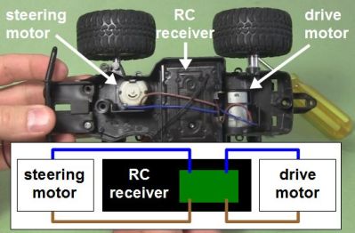
I have an RC receiver that I’ve taken from a toy truck. When it was in the truck, it controlled two DC motors: one for driving backwards and forwards, and the other for steering left and right. That means the motors are told to rotate either clockwise or counterclockwise as needed. To make a DC motor rotate in one direction you connect the two wires one way, and to make it rotate in the other direction you reverse the two wires, or you reverse the polarity. None of the output wires are common inside the RC receiver, something I discovered the hard way as you’ll see below.
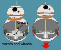
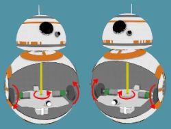
I wasn’t using the RC receiver with the toy truck. I extracted it from the truck and was using it to control my BB-8 droid. My BB-8 droid has two motors configured as what in the BB-8 builders world is called a hamster drive, though is more widely known as a tank drive or differential drive (see the illustrations). Rotate both wheels in the same direction with respect to the droid and the droid moves in that direction. Reverse both wheels and it drives in the opposite direction. Make the wheels rotate in opposite directions and it turns on the spot.
The big picture – RC to drill motors
The motors in my BB-8 are drill motors and are controlled by two H-bridge boards. An Arduino does pulse width modulation to the H-bridge boards for speed control, and controls which direction the motors should turn. Finally, the RC receiver is what tells the Arduino what to do. But a converter board, the subject of this article, is needed between the RC receiver and the Arduino. Note that the Arduino is necessary also for countering when the BB-8 droid wobbles and for synchronizing sounds with the movement, but those aren’t addressed here.
Since there are two motors and two directions for each motor, the RC receiver needs to control four pins on the Arduino to make the two drill motors behave as follows: motor 1/clockwise, motor 1/counterclockwise, motor 2/clockwise, motor 2/counterclockwise. And whatever voltages the receiver puts on those pins has to be relative to the Ardunio’s ground.
And herein lies the problem. The Arduino expects positive voltages with respect to its ground on all those pins. So I needed a way to map the RC receiver’s two sets of motor control wires, which can have either positive or negative voltages across them, to the Arduino pins which only want positive voltages. And remember, none of those RC receiver wires are common inside the receiver.
My Fumbling First Approach
Now, keep in mind, electronics is a general interest of mine and except for what we were taught in high school physics class, I’m self-taught. That means I’ve “read ahead” but much of my knowledge has been determined by what projects I’ve done. So I have gaps in my knowledge. I’d never turned negative voltages into positive before. It sounded simple enough. Searching online didn’t help though. The closest I got was in two old posts in forums where the answers were “It’s easy to do. I can do it with a single resistor.” But there was no further explanation and I didn’t ask my own question anywhere at that point.
Using a transistor
Instead I came up with my own approach with just one set of wires from the RC receiver first. The wires coming from the receiver were blue and brown and could have either polarity depending on which way the receiver is being told to rotate the motor: clockwise or counterclockwise. That meant I needed two diodes to create two possible paths for the different polarities the brown wire could be: positive or negative. I then added a battery for the one path that was negative, to turn it into a positive.
Next, I put a PNP transistor between the positive of the battery and the receiver. With no signal from the RC transmitter, the transistor’s base is negative with respect to the emitter, but not enough to turn the transistor on. That’s because the battery’s negative is connected to the receiver’s blue wire and since there’s no signal from the transmitter, the brown wire is also at the same potential as the blue wire, and with battery negative.
The idea was that when the transmitter sent a signal to make that brown wire negative with respect to the blue wire, it would become even more negative and turn on the PNP transistor. A positive signal would then go from the battery, through the transistor to the Arduino.
The most obvious problem was that the Arduino wanted to see 3 volts to register as a HIGH input, meaning the battery would have to be at least 3 volts and so even with no signal from the transmitter, that would be -3 volts to the transistor, turning it on when it wasn’t supposed to be on.
Using A Relay Instead
Using a relay
And so I immediately thought of using a relay instead. I’d use the current running through the negative path to energize the relay, closing a switch that was completely independent of the RC receiver. The Arduino has a 5V output pin, so I made that switch close a circuit between the 5V pin and the Arduino’s pin 7, giving pin 7 the needed positive voltage.
The 1 in the circle in the schematic shows where I wanted to put a resistor in order to limit the current going through the relay’s coil. However, I tried with resistors all the way down to 4.7 ohms but the coil didn’t have enough current to close the switch. With no resistor, it worked and the current was 70mA. The relay’s coil was rated for 3V/120mA so I left it.
Using a relay did seem very heavy-handed, but it was the only solution I could come up with and I already had the relay in stock.
The next step was to add a second relay, doing the same for the second set of wires coming from the RC receiver for the second motor.
No Common In The Receiver
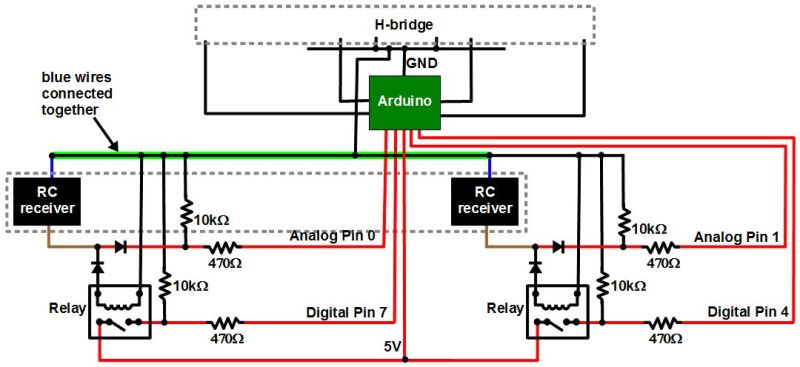
Schematic with common blue RC wires
But the behavior was seemingly sporadic. And keep in mind that there was a whole dual H-bridge circuit that was also connected to the Arduino’s ground. I’d worked with relays a lot before, and the RC receiver came from a commercially made and functional toy so I had no reason to suspect that. On the other hand, I’d made the H-bridge circuit from scratch since I already had most of the parts, and I was new to H-bridges and MOSFETs. So at first I spent a good two weeks of spare time thinking my problem was with the H-bridge and drill motor side. I’m sure we’ve all experienced the same blindness, thinking the most likely culprit is the part you had a hand in.
But at some point I disconnected the H-bridge and tested just the RC receiver circuit, watching the voltages at the Arduino pins while I remotely turned on both “motors” in both directions in all combinations (no motors were connected at the time though). The only odd behavior I saw was when I turned the motors on in opposite directions.
Notice in the schematic that I’d connected together both blue wires coming from the RC receiver. Up to that point I’d been assuming that the blue wires were common inside the receiver and that it was only the brown wires that switched from positive to negative with respect to the blue wires. From the behavior I was seeing it looked like both wires were switching polarity, possibly around some other internal common reference.
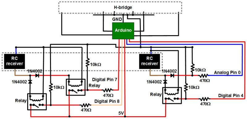
Finished RC-to-Arduino converter schematic
So I added a third relay on one of the positive paths of one of the sets of wires. That meant the corresponding blue wire no longer needed to be grounded, keeping both of the receiver’s blue wires separate. Note that I didn’t bother putting in a fourth relay for the remaining positive path, and it turned out to not be necessary. At that point the circuits worked great and continue to do so.
The Ask
And so I ask, is there a better way to convert the RC receiver output to something the Arduino can use? Relays require power, so it would be nice if there was a solution that didn’t require any extra power. My relay solution seems very early 1900s. Or maybe it’s a good solution after all, but just one of many. Let us know in the comments below.


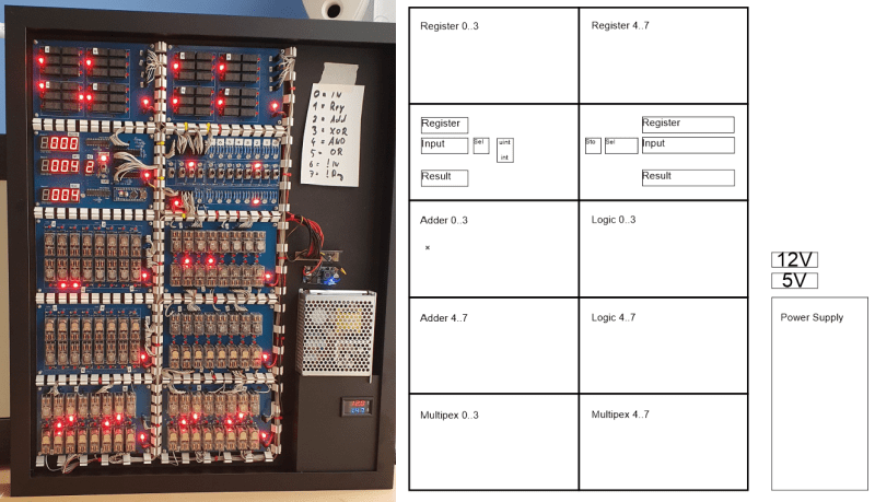
 operating on 4-bits. To handle a byte-length word, boards are simply cascaded, making a total of eight. The register, adder, logic function, and multiplex boards are the heart of the build with an additional two custom boards for visualization (using an Arduino for convenience) and IO forming the interface. After all, a basic CPU is just an ALU and some control around it, the magic is really in the ALU.
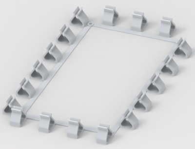 but that’s the job of a separate board. The adder function is the most basic, simply a pair of half-adders and an OR-gate to handle the chaining of the carry inputs and generate the carry chain output.