Posts with «iot» label

Tutorial – Ethernet Shields and Arduino

In this chapter we will introduce and examine the use of Ethernet networking with Arduino over local networks and the greater Internet.

It will be assumed that you have a basic understanding of computer networking, such as the knowledge of how to connect computers to a hub/router with RJ45 cables, what an IP and MAC address is, and so on. Furthermore, here is a good quick rundown about Ethernet.

Getting Started

You will need an Arduino Uno or compatible board with an Ethernet shield that uses the W5100 Ethernet controller IC (pretty much all of them):

Furthermore you will need to power the board via the external DC socket – the W5100 IC uses more current than the USB power can supply. A 9V 1.5A plug pack/wall wart will suffice.

Finally it does get hot – so be careful not to touch the W5100 after extended use. In case you’re not sure – this is the W5100 IC:

Once you have your Ethernet-enabled Arduino, and have the external power connected – it’s a good idea to check it all works. Open the Arduino IDE and select File > Examples > Ethernet > Webserver. This loads a simple sketch which will display data gathered from the analogue inputs on a web browser. However don’t upload it yet, it needs a slight modification.

You need to specify the IP address of the Ethernet shield – which is done inside the sketch. This is simple, go to the line:

IPAddress ip(192,168,1, 177);

And alter it to match your own setup. For example, in my home the router’s IP address is 10.1.1.1, the printer is 10.1.1.50 and all PCs are below …50. So I will set my shield IP to 10.1.1.77 by altering the line to:

IPAddress ip(10,1,1,77);

You also have the opportunity to change your MAC address. Each piece of networking equipment has a unique serial number to identify itself over a network, and this is normall hard-programmed into the equipments’ firmware. However with Arduino we can define the MAC address ourselves.

If you are running more than one Ethernet shield on your network, ensure they have different MAC addresses by altering the hexadecimal values in the line:

byte mac[] = { 0xDE, 0xAD, 0xBE, 0xEF, 0xFE, 0xED };

However if you only have one shield just leave it be. There may be the very, very, statistically rare chance of having a MAC address the same as your existing hardware, so that would be another time to change it.

Once you have made your alterations, save and upload the sketch. Now open a web browser and navigate to the IP address you entered in the sketch, and you should be presented with something similar to the following:

What’s happening? The Arduino has been programmed to offer a simple web page with the values measured by the analogue inputs. You can refresh the browser to get updated values.

At this point – please note that the Ethernet shields use digital pins 10~13, so you can’t use those for anything else. Some Arduino Ethernet shields may also have a microSD card socket, which also uses another digital pin – so check with the documentation to find out which one.

Nevertheless, now that we can see the Ethernet shield is working we can move on to something more useful. Let’s dissect the previous example in a simple way, and see how we can distribute and display more interesting data over the network. For reference, all of the Ethernet-related functions are handled by the Ethernet Arduino library. If you examine the previous sketch we just used, the section that will be of interest is:

 for (int analogChannel = 0; analogChannel < 6; analogChannel++) 
          {
            int sensorReading = analogRead(analogChannel);
            client.print("analog input ");
            client.print(analogChannel);
            client.print(" is ");
            client.print(sensorReading);
            client.println("<br />");       
          }
          client.println("</html>");

Hopefully this section of the sketch should be familiar – remember how we have used serial.print(); in the past when sending data to the serial monitor box? Well now we can do the same thing, but sending data from our Ethernet shield back to a web browser – on other words, a very basic type of web page.

However there is something you may or may not want to  learn in order to format the output in a readable format – HTML code. I am not a website developer (!) so will not delve into HTML too much.

However if you wish to serve up nicely formatted web pages with your Arduino and so on, here would be a good start. In the interests of simplicity, the following two functions will be the most useful:

client.print(" is ");

Client.print (); allows us to send text or data back to the web page. It works in the same way as serial.print(), so nothing new there. You can also specify the data type in the same way as with serial.print(). Naturally you can also use it to send data back as well. The other useful line is:

client.println("<br />");

which sends the HTML code back to the web browser telling it to start a new line. The part that actually causes the carriage return/new line is the <br /> which is an HTML code (or “tag”) for a new line. So if you are creating more elaborate web page displays, you can just insert other HTML tags in the client.print(); statement.

If you want to learn more about HTML commands, here’s a good tutorial site. Finally – note that the sketch will only send the data when it has been requested, that is when it has received a request from the web browser.

Accessing your Arduino over the Internet

So far – so good. But what if you want to access your Arduino from outside the local network?

You will need a static IP address – that is, the IP address your internet service provider assigns to your connection needs to stay the same. If you don’t have a static IP, as long as you leave your modem/router permanently swiched on your IP shouldn’t change. However that isn’t an optimal solution.

If your ISP cannot offer you a static IP at all, you can still move forward with the project by using an organisation that offers a Dynamic DNS. These organisations offer you your own static IP host name (e.g. mojo.monkeynuts.com) instead of a number, keep track of your changing IP address and linking it to the new host name. From what I can gather, your modem needs to support (have an in-built client for…) these DDNS services. As an example, two companies are No-IP andDynDNS.com. Please note that I haven’t used those two, they are just offered as examples.

Now, to find your IP address… usually this can be found by logging into your router’s administration page – it is usually 192.168.0.1 but could be different. Check with your supplier or ISP if they supplied the hardware. For this example, if I enter 10.1.1.1 in a web browser, and after entering my modem administration password, the following screen is presented:

What you are looking for is your WAN IP address, as you can see in the image above. To keep the pranksters away, I have blacked out some of my address.

The next thing to do is turn on port-forwarding. This tells the router where to redirect incoming requests from the outside world. When the modem receives such a request, we want to send that request to the port number of our Ethernet shield. Using the:

EthernetServer server(125);

function in our sketch has set the port number to 125. Each modem’s configuration screen will look different, but as an example here is one:

So you can see from the line number one in the image above, the inbound port numbers have been set to 125, and the IP address of the Ethernet shield has been set to 10.1.1.77 – the same as in the sketch.

After saving the settings, we’re all set. The external address of my Ethernet shield will be the WAN:125, so to access the Arduino I will type my WAN address with :125 at the end into the browser of the remote web device, which will contact the lonely Ethernet hardware back home.

Furthermore, you may need to alter your modem’s firewall settings, to allow the port 125 to be “open” to incoming requests. Please check your modem documentation for more information on how to do this.

Now from basically any Internet connected device in the free world, I can enter my WAN and port number into the URL field and receive the results. For example, from a phone when it is connected to the Internet via LTE mobile data:

So at this stage you can now display data on a simple web page created by your Arduino and access it from anywhere with unrestricted Internet access. With your previous Arduino knowledge you can now use data from sensors or other parts of a sketch and display it for retrieval.

Displaying sensor data on a web page

As an example of displaying sensor data on a web page, let’s use an inexpensive and popular temperature and humidity sensor – the DHT22. You will need to install the DHT22 Arduino library which can be found on this page. If this is your first time with the DHT22, experiment with the example sketch that’s included with the library so you understand how it works.

Connect the DHT22 with the data pin to Arduino D2, Vin to the 5V pin and GND to … GND.

Now for our sketch – to display the temperature and humidity on a web page. If you’re not up on HTML you can use online services such as this to generate the code, which you can then modify to use in the sketch.

In the example below, the temperature and humidity data from the DHT22 is served in a simple web page:

#include <SPI.h>
#include <Ethernet.h>

// for DHT22 sensor
#include "DHT.h"
#define DHTPIN 2
#define DHTTYPE DHT22

// Enter a MAC address and IP address for your controller below.
// The IP address will be dependent on your local network:
byte mac[] = {   0xDE, 0xAD, 0xBE, 0xEF, 0xFE, 0xED };
IPAddress ip(10,1,1,77);

// Initialize the Ethernet server library
// with the IP address and port you want to use 
// (port 80 is default for HTTP):
EthernetServer server(125);
DHT dht(DHTPIN, DHTTYPE);

void setup() 
{
  dht.begin();
 // Open serial communications and wait for port to open:
  Serial.begin(9600);
   while (!Serial) {
    ; // wait for serial port to connect. Needed for Leonardo only
  }
  // start the Ethernet connection and the server:
  Ethernet.begin(mac, ip);
  server.begin();
  Serial.print("server is at ");
  Serial.println(Ethernet.localIP());
}

void loop() 
{
  // listen for incoming clients
  EthernetClient client = server.available();
  if (client) {
    Serial.println("new client");
    // an http request ends with a blank line
    boolean currentLineIsBlank = true;
    while (client.connected()) {
      if (client.available()) {
        char c = client.read();
        Serial.write(c);
        // if you've gotten to the end of the line (received a newline
        // character) and the line is blank, the http request has ended,
        // so you can send a reply
        if (c == 'n' && currentLineIsBlank) 
        {
          // send a standard http response header
          client.println("HTTP/1.1 200 OK");
          client.println("Content-Type: text/html");
          client.println("Connection: close");  // the connection will be closed after completion of the response
	  client.println("Refresh: 30");  // refresh the page automatically every 30 sec
          client.println();
          client.println("<!DOCTYPE HTML>");
          client.println("<html>");

          // get data from DHT22 sensor
          float h = dht.readHumidity();
          float t = dht.readTemperature();
          Serial.println(t);
          Serial.println(h);

          // from here we can enter our own HTML code to create the web page
          client.print("<head><title>Office Weather</title></head><body><h1>Office Temperature</h1><p>Temperature - ");
          client.print(t);
          client.print(" degrees Celsius</p>");
          client.print("<p>Humidity - ");
          client.print(h);
          client.print(" percent</p>");
          client.print("<p><em>Page refreshes every 30 seconds.</em></p></body></html>");
          break;
        }
        if (c == 'n') {
          // you're starting a new line
          currentLineIsBlank = true;
        } 
        else if (c != 'r') {
          // you've gotten a character on the current line
          currentLineIsBlank = false;
        }
      }
    }
    // give the web browser time to receive the data
    delay(1);
    // close the connection:
    client.stop();
    Serial.println("client disonnected");
  }
}

It is a modification of the IDE’s webserver example sketch that we used previously – with a few modifications. First, the webpage will automatically refresh every 30 seconds – this parameter is set in the line:

client.println("Refresh: 30");  // refresh the page automatically every 30 sec

… and the custom HTML for our web page starts below the line:

// from here we can enter our own HTML code to create the web page

You can then simply insert the required HTML inside client.print() functions to create the layout you need.

Finally – here’s an example screen shot of the example sketch at work:

You now have the framework to create your own web pages that can display various data processed with your Arduino.

Conclusion

I hope you enjoyed making this or at least reading about it. If you find this sort of thing interesting, please consider ordering one or more of my books from amazon.

And as always, have fun and make something.

To keep up to date with new posts at tronixstuff.com, please subscribe to the mailing list in the box on the right, or follow us on twitter @tronixstuff.

Tronixstuff 09 Apr 08:09

New Brains Save 12 V Fridge From the Scrap Heap

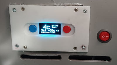
Recently [nibbler]’s Evakool 55L vehicle fridge started to act strangely, reporting crazy temperature errors and had no chance of regulating. The determination was that the NTC thermistor was toast, and rather than trying to extricate and replace this part, it was a lot easier to add a new one at a suitable location

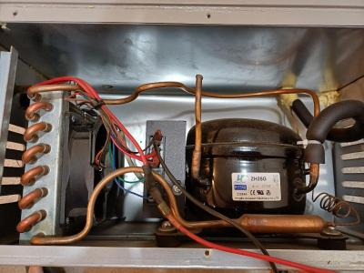
Bog-standard fridge internals

A straight swap would have been boring, so this was a perfect excuse for an overboard hack. Reverse engineering the controller wouldn’t be easy, as the data wasn’t available, as is often the case for many products of this nature.

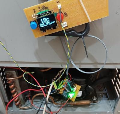
While doing a brain transplant, the hacker way, we can go overboard and add the basics of an IoT control and monitoring system. To that end, [nibbler] learned as much as possible about the off-the-shelf ZH25G compressor and the associated compressor control board. The aim was to junk the original user interface/control board and replace that with a Raspberry Pi Pico W running CircuitPython.

For the display, they used one of the ubiquitous SH1106 monochrome OLED units that can be had for less than the cost of a McDonald’s cheeseburger at the usual purveyors of cheap Chinese electronics.  A brief distraction was trying to use a DS18B20 waterproof thermometer probe, which they discovered didn’t function, so they reverted to tried and trusted tech — a simple NTC thermistor.

Testing testing

The final puzzle piece was to interface the Pico to the compressor controller. The controller expected a variable resistance to control the speed, for which they could have used a digitally controlled potentiometer. However, after failing to tame this particular beast, an easier solution was to build a small PCB with a few relays and some fixed resistors and call it a hack.

An annoyance was the lack of interrupt support in CircuitPython. This meant that interpreting the fault codes from the controller would be a bit tricky. The solution was to wedge in another microcontroller, a small Arduino. Its job is to sit there, listen for commands on the serial port, control the relay board to drive the compressor, listen for any error codes, and pass those back to the Pico. Of course, this could have all been done directly on the Pico, just not with CircuitPython, and a lot more learning would have been needed.

Of course, you need to own a working refrigerator to hack it, but you can easily build it from scratch. Even on a tight budget, you can get your beers cold. Needs must!

Keeping Miners Safe With Arduino

Note: If you are considering a vacation in Italy in October, remember that Maker Faire Rome The European Edition, one of the world’s largest Maker Faires, will be taking place in Rome from the 20th to the 22nd. The mining industry, often hailed as the backbone of the Indian economy, plays a crucial role in […]
MAKE » Arduino 20 Jul 15:02
arduino  iot  maker faire  

Cat Skull for Internet Connection Divination

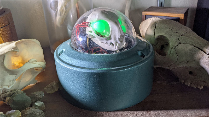
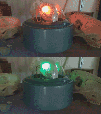
[Emily Velasco] has an internet provider that provides sub-par connectivity. Instead of repeatedly refreshing a browser tab to test if the network is up, [Emily] decided to create an internet status monitor by embedding indicator lights in a cat skull…for some reason.

The electronics are straightforward, with the complete parts list consisting of an Arduino Nano 33 IoT device connected to a pair of RGB LEDs and 50 Ohm resistors. The Nano attempts to connect to a known site (in this case, the Google landing page) every two seconds and sets the LEDs to green if it succeeds or red if it fails.

The cat skull is thankfully a replica, 3D printed by one of [Emily]’s Twitter acquaintances, and the whole project was housed in a domed security camera enclosure. [Emily] mounts the LEDs into the skull to create a “brain in a jar” effect.

The source is available on GitHub for those wanting to take a look. We’ve featured internet connectivity status indicators in the form of traffic lights here before, as well as various network status monitors and videoconferencing indicator lights.

Mighty Modules: Pluggable Boards To Get Your Project Built

If you're taking your microcontroller or SBC project to market, these pluggable boards might be what you need.

The post Mighty Modules: Pluggable Boards To Get Your Project Built appeared first on Make: DIY Projects and Ideas for Makers.

Build a simple WFH Messaging System

Working from home – either you enjoy it, or doing so has been thrust upon you. As a world-class introvert I’ve always enjoyed being self-employed and working from my own office. However others do not, as they have missed out on the activity and interacting with other people in their workplace.

I was recently asked by an associate to make up a simple messaging system, that would allow them to indicate their work status and also request a coffee or whatnot from their husband, which has resulted in the simple messaging system described in this article – which you can build too.

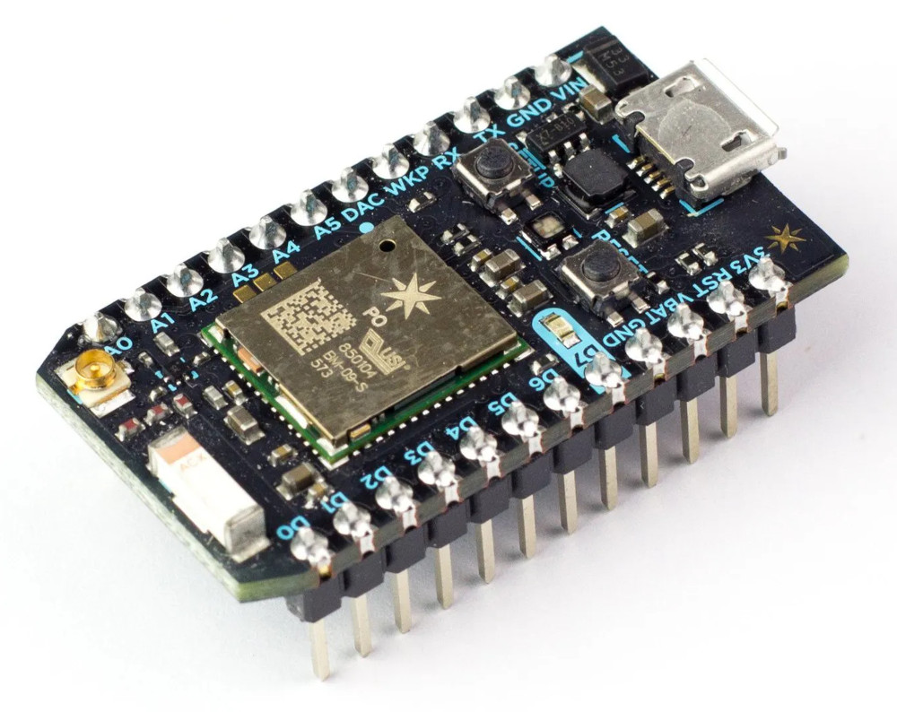
Being somewhat lazy efficient I needed a simple WiFi-based solution that allowed for simple control of some digital output pins from a web page. A bit of research resulted with the Particle Photon, a compact WiFi-enabled microcontroller that includes all the Internet-connectivity without any hard work or recurring payments.

After consultation it was decided that there should be five messages that can be sent and will need to be indicated to the receiver:

  • “I’m in a meeting, do not disturb”
  • “I’m working alone, so I can be disturbed”
  • Bring coffee
  • Bring Water
  • “I’ve finished work for the day”

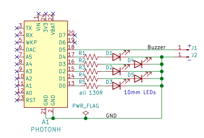
So that would need the control of five LEDs, and a buzzer to alert the receiver of new messages. Six digital outputs in total to be controlled remotely. Easily done with the Photon.

All the digital outputs on the Photon are 3.3V, and you can power the lot via the micro USB socket. Now let’s get started. I’ll go through the hardware first, then the software and connectivity.

Hardware

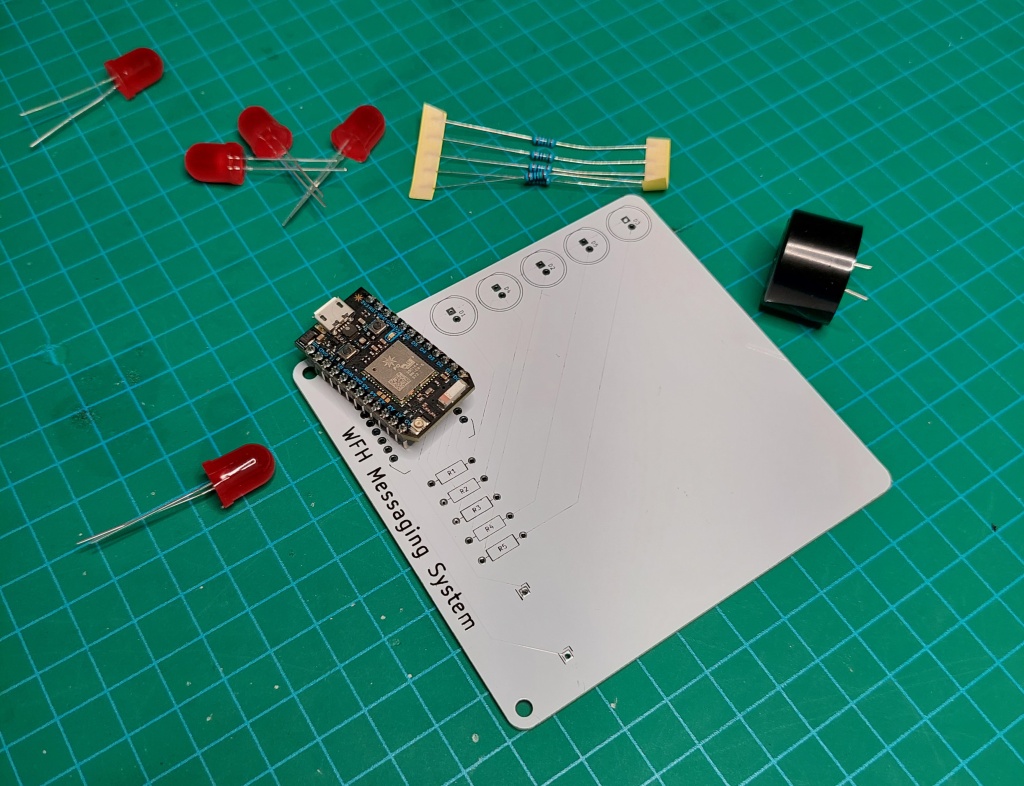
First, let’s consider the hardware. We’ll need:

The whole thing is a minimalist design, as shown below:

The PCB shown in this article was made for a buzzer with 16mm between the pins, as it was available locally. If soldering is new to you, or you need a refresher – watch Dave Jones’ video.

This is a simple circuit you can knock out on a solderless breadboard or your own PCB with KiCAD). Click here for the Photon KiCAD library. Click here if you want the gerber files to order your own PCB. You can view the gerbers using tools such as gerblook.

At the time of writing this I have a few PCBs left over… if you live in Australia I’ll send you one for free – email admin@tronixstuff.com.

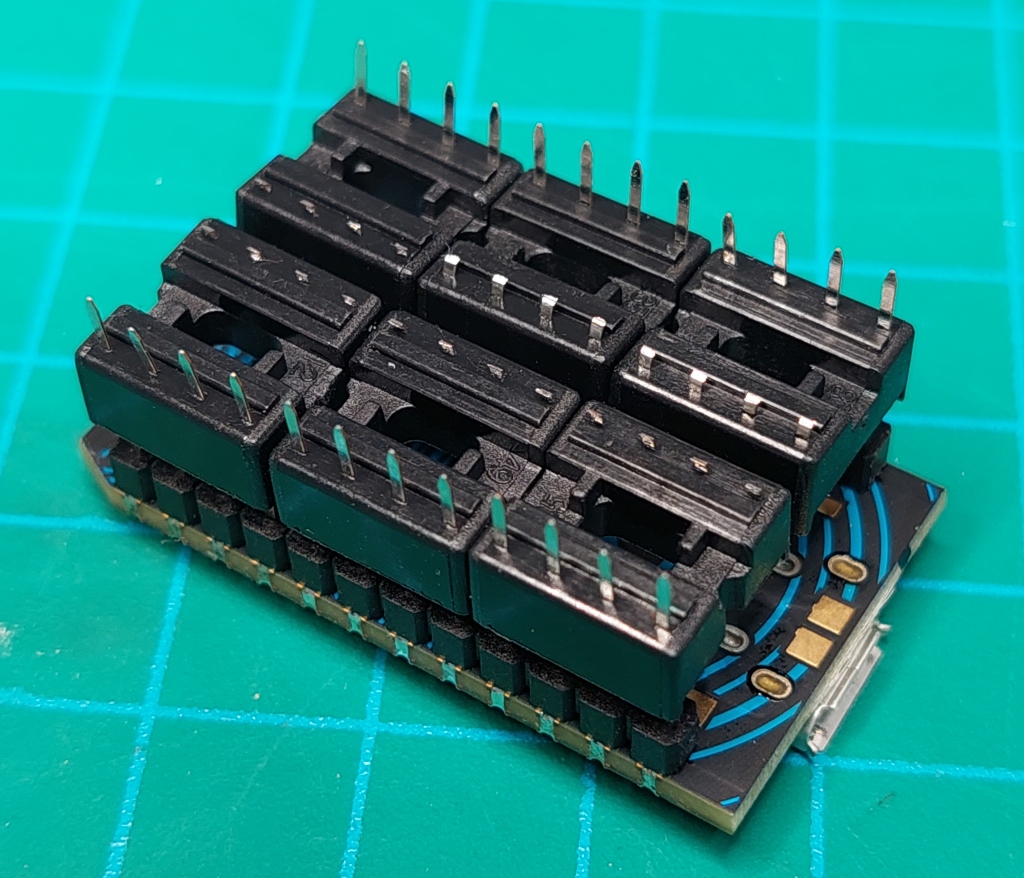
In my infinite wisdom I forgot to get some inline header sockets (as you don’t really want to directly solder the Photon to the PCB). However having hundreds spare, a work around was to use six 8 pin IC sockets, and trim one side of the pins off from each socket. Which worked …well enough:

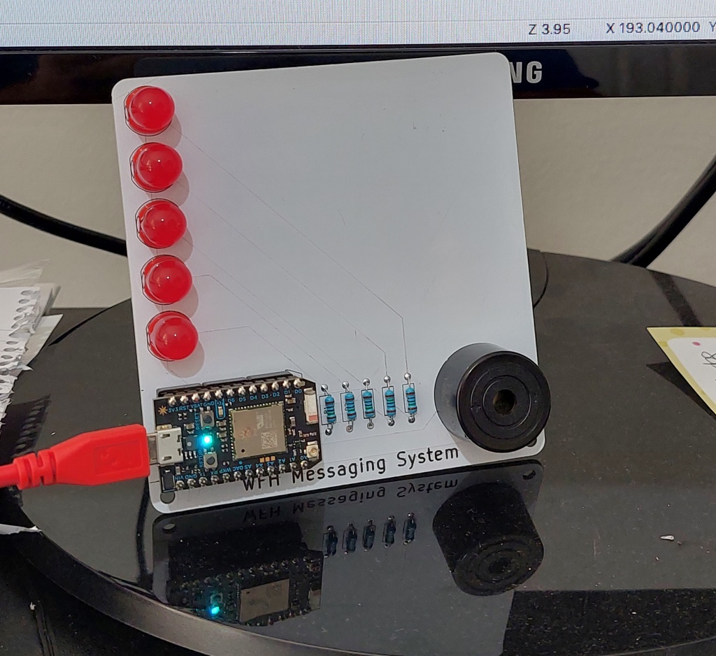
Fitting the rest of the parts was a doddle, and resulted with the following board:

The messages were purposely not printed on the PCB silkscreen, instead all that white space is for the users to apply their own labels – as they may want to change the messages later on.

The M3 threaded spacers and nuts are fitted to the holes on the PCB to give it some legs to stand up on. So now that the hardware is finished, it’s time to get all this working with the code and connectivity.

Software and Connectivity

There are a few steps for you to complete in order to build this system, and I’ll run through them in order now.

First, follow the instructions provided by Particle which will involve you setting up a Particle account, registering and testing your Photon. During this process you will be given your “device ID” – save this as you’ll need it later. It will also save the WiFi access point details into the Photon, so do this step using the WiFi network that will host the messaging system.

Next, install the Particle CLI (Command Line Interface). It is available for Windows, Linux and MacOS. This takes about five minutes, so get up and have a stretch.

Now you need an access token, a unique identifier for your Particle account. Open the terminal on your computer and run the command “particle token create”. You’ll be prompted for your Particle account email address and password, then presented with the token (the long random string of text). Save the token for later.

I’ve blocked out my email address and part of the token to keep troublemakers at bay.

The next step is to build the web page that contains the buttons to be pressed to send the required messages. Open a simple text editor and save the following to a .html file.

https://cdn.jsdelivr.net/npm/particle-api-js@8/dist/particle.min.js var particle = new Particle(); // This is incredibly insecure, and only ideal for local tasks of no consequence if things go wrong. const accessToken = ‘ENTER YOUR ACCESS TOKEN HERE’; const deviceId = ‘ENTER YOUR DEVICE ID HERE’; function ledControl(cmd) { // Used to turn on or off the LED by using the Particle.function “led” document.getElementById(“statusSpan”).innerHTML = ”; particle.callFunction({deviceId, name:’led’, argument: cmd, auth:accessToken}).then( function(data) { document.getElementById(“statusSpan”).innerHTML = ‘Message sent.’; }, function(err) { document.getElementById(“statusSpan”).innerHTML = ‘Error calling device: ‘ + err; } ); }

WFH Messaging System

Working Alone.  In a meeting – DND.

I need coffee!  Please bring me some water.

Finished for the day. 


Enter your access token and device ID as noted in the HTML file. Just for the record, this system is incredibly insecure and shouldn’t be used for anything of any consequence, so if you modify this to control your door locks or alarm system, that’s on you.

You don’t need to be an expert on HTML, however if you’re not sure about it check out this great HTML tutorial site.

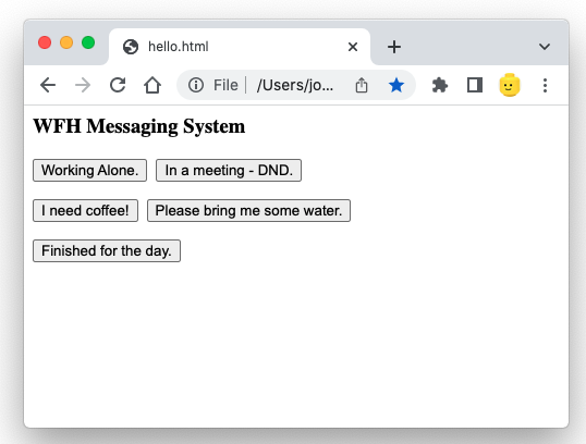
Now open the file using a web browser, and make it a bookmark for the user to easily fine. You will be presented with a simple interface:

You can easily change the text on each button, just edit the HTML and save the file. Now review the HTML, and note that for each button there’s the text (for example):

onclick=”ledControl(‘D1On’)”>Working Alone.

This snippet will send the text “D1On” back to the Photon when the button “Working Alone.” is pressed. The idea is that we need all the buttons to send back a unique message to the Photon, so it knows what to do with the LEDs and/or buzzer. Take note that each button press sends a different piece of text back to the Photon.

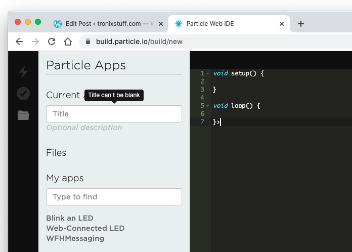
Moving on, we now need to enter and upload the code to the Photon. In a web browser, visit https://build.particle.io/build/new. You may need to log in to your Particle account during this process. After a moment, you’ll be presented with a text editor that may look familiar to anyone working with Arduino. Photon code is based off the Arduino plaform, so Arduino users or AVR C users will have a head start.

Give your project a title, then copy and paste the following code into the editor:

// WFH Messaging system.
// Modified version of code provided by particle.io documentation.
// Use at your own risk.

int led0 = D0;
int led1 = D1;
int led2 = D2;
int led3 = D3;
int led4 = D4;
int buzzer = D5;

void setup()
{
   // set pins connected to LEDs and buzzer as outputs
   pinMode(led0, OUTPUT);
   pinMode(led1, OUTPUT);
   pinMode(led2, OUTPUT);
   pinMode(led3, OUTPUT);
   pinMode(led4, OUTPUT);
   pinMode(buzzer, OUTPUT);

   // We are also going to declare a Particle.function so that we can turn the LEDs on and off from the cloud.
   Particle.function("led",ledToggle);
   // This is saying that when we ask the cloud for the function "led", it will employ the function ledToggle() from this app.

   // Turn off LEDs upon reset
   digitalWrite(led0, LOW);
   digitalWrite(led1, LOW);
   digitalWrite(led2, LOW);
   digitalWrite(led3, LOW);
   digitalWrite(led4, LOW);
   digitalWrite(buzzer, LOW);
}

void loop()
{
   // Nothing to do here as waiting for text from control webpage
}

void soundAlert()
{
    digitalWrite(buzzer, HIGH);
    delay(1000);
    digitalWrite(buzzer, LOW);
}

void coffeeAlert()
{
    for (int i=0; i<5; i++)
    {
        digitalWrite(buzzer, HIGH);
        delay(100);
        digitalWrite(buzzer, LOW);
        delay(100);
    }
}

void waterAlert()
{
    for (int i=0; i<2; i++)
    {
        digitalWrite(buzzer, HIGH);
        delay(500);
        digitalWrite(buzzer, LOW);
        delay(100);
    }
}


int ledToggle(String command) {
// function receives a string from control webpage (the commands such as D0On) and acts on them

    if (command=="D0On") {
        digitalWrite(led0,HIGH); // in a meeting - DND
        digitalWrite(led1,LOW); // turn off working alone LED
        digitalWrite(led4,LOW); // turn off finished for the day LED
        soundAlert();
        return 1;
    }
    else if (command=="D1On") {
        digitalWrite(led1,HIGH); // working alone
        digitalWrite(led0,LOW);  // turn off DND LED
        digitalWrite(led4,LOW); // turn off finished for the day LED        
        soundAlert();        
        return 0;
    }
     else if (command=="D2On") {
        digitalWrite(led2,HIGH); // coffee request
        coffeeAlert();        
        delay(2000); 
        digitalWrite(led2,LOW); 
        return 0;
    }
     else if (command=="D3On") {
        digitalWrite(led3,HIGH); // water request
        waterAlert();        
        delay(2000); 
        digitalWrite(led3,LOW); 
        return 0;
    }    
     else if (command=="D4On") {
        digitalWrite(led4,HIGH); // finished for the day
        digitalWrite(led0,LOW);  // cancel DND LED if on
        digitalWrite(led1,LOW);  // cancel working alone LED if on
        soundAlert();
        return 0;
    }      
    
    else {
        return -1;
    }
}

This code configures the digital output pins for the LEDs and buzzer from lines 5 to 10, which are then set to outputs from lines 15 to 20. We then turn them all off from lines 27 to 32, so every time the Photon is reset or turned on after a power off, no LEDs or the buzzer are on.

On line 23 we have the following:

Particle.function("led",ledToggle);

This the link between the code on the HTML page you created earlier, and the function starting from line 70 in the Photon code. “led” is linked in the HTML line with “particle.callFunction”, and “ledToggle” is the function in the Photon code.

So whenever a button is pressed, the message (such as “D4On”) winds its way from the web browser via the magic of the Internet to the Photon, and then compared against the “if” statements in the function from line 73.

For example, when “D4On” is received, it is matched at line 101 by the Photon, which then turns on LED number 4 (for “Finished for today”), and also turns off the “DND” and “Working Alone” LEDs.

For all the other messages you can follow the code from line 73 to see how each button press on the webpage controls various combinations of LEDs and buzzer outputs. To save time there’s three custom buzzer functions that are used for differents audible alerts, so the message recipient can hear if the sender’s status has changed, or if they want a coffee or water. Pity the end user of this.

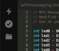
Finally, when you’ve entered the code in the Photon editor, click the little folder a the top-left of the screen which saves your code in the online storage provided by Particle:

Then you can upload the code to the Photon by clicking the lightning bolt. If there are no errors in the code, it will be compiled and shot off to the Photon. During this process, the LED on the Photon will blink slowly then quickly, then “breathe” on and off when it’s ready to go.

This could take up to a minute depending on your Internet connection. However if there’s something wrong, this will be shown in the bottom of the Photon editor page. Follow the messages to determine what’s wrong, then save and try again.

By now it should all be working. Now add labels next to the LEDs for the recipient to know what the sender is trying to say or demand, and you’re finished. A quick demonstration is shown in the following video:

So there you have it. On a broader sense, this can also be considered a demonstration of how to easily control things from a distance using a Particle Photon and a web-enabled device.

I hope you enjoyed making this or at least reading about it. If you find this sort of thing interesting, please consider ordering one or both of my books from No Starch Press, or other book sellers:

  • Arduino Workshop, 2nd Edition – a hands-on introduction to electronics and Arduino with 65 projects
  • AVR Workshop – A comprehensive introduction to working with electronics and the Microchip AVR 8-bit family of microcontrollers with over 55 projects

And as always, have fun and make something.

Tronixstuff 03 Apr 06:01
iot  particle  photon  

Impressive Off-Grid Hydroelectric Plant Showcases The Hacker Spirit

We all know the story arc that so many projects take: Build. Fail. Improve. Fail. Repair. Improve. Fail. Rebuild. Success… Tweak! [Kris Harbour] is no stranger to the process, as his impressive YouTube channel testifies.

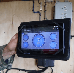
An IOT charge controller makes power management easier.

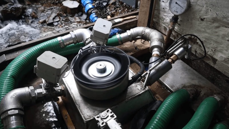
Among all of [Kris’] off-grid DIY adventures, his 500 W micro hydroelectric turbine has us really pumped up. The impressive feat of engineering features Arduino/IOT based controls, 3D printed components, and large number of custom-machined components, with large amounts of metal fabrication as well.

[Kris] Started the build with a Pelton wheel sourced from everyone’s favorite online auction site paired with an inexpensive MPPT charge controller designed for use with solar panels. Eventually the turbine was replaced with a custom built unit designed to produce more power. An Arduino based turbine valve controller and an IOT enabled charge controller give [Kris] everything he needs to manage the hydroelectric system without having to traipse down to the power house. Self-cleaning 3D printed screens keep intake maintenance to a minimum. Be sure to check out a demonstration of the control system in the video below the break.

As you watch the Hydro electric system playlist, you see the hacker spirit run strong throughout the initial build, the failures, the engineering, the successes, and then finally, the tweaking for more power. Because why stop at working when it can be made better, right? We highly recommend checking it out- but set aside some time. The whole series is oddly addictive, and This Hackaday Writer may have spent inordinate amounts of time watching it instead of writing dailies!

Of course, you don’t need to go full-tilt to get hydroelectric power up and running. Even at a low wattage, its always-on qualities mean that even a re-purposed washing machine can be efficient enough to be quite useful.

Thanks to [Mo] for alerting us to the great series via the Tip Line!

Open Source Electric Vehicle Charging

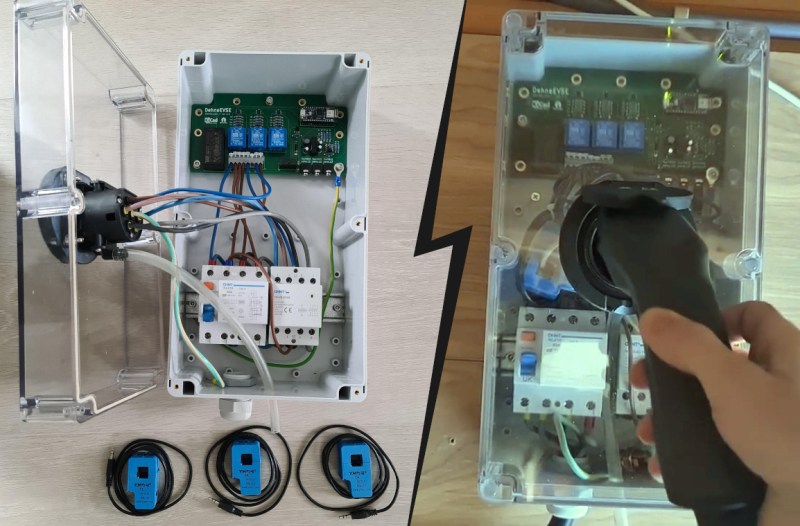
Electric vehicles are becoming more and more common on the road, but when they’re parked in the driveway or garage there are still some kinks to work out when getting them charged up. Sure, there are plenty of charging stations on the market, but they all have different features, capabilities, and even ports, so to really make sure that full control is maintained over charging a car’s batteries it might be necessary to reach into the parts bin and pull out a trusty Arduino.

This project comes to us from [Sebastian] who needed this level of control over charging his Leaf, and who also has the skills to implement it from the large high voltage switching contactors to the software running its network connectivity and web app. This charging station has every available feature, too. It can tell the car to charge at different rates, and can restrict it to charging at different times (if energy is cheaper at night, for example). It is able to monitor the car’s charge state and other information over the communications bus to the vehicle, and even has a front-end web app for monitoring and controlling the device.

The project is based around an Arduino Nano 33 IoT with all of the code available on the project’s GitHub page. While we would advise using extreme caution when dealing with mains voltage and when interfacing with a high-ticket item like an EV, at first blush the build looks like it has crossed all its Ts and might even make a good prototype for a production unit in the future. If you don’t need all of the features that this charging station has, though, you can always hack the car itself to add some more advanced charging features.

Speaker Snitch Tattles on Privacy Leaks

A wise senator once noted that democracy dies with thunderous applause. Similarly, it’s also how privacy dies, as we invite more and more smart devices willingly into our homes that are built by companies that don’t tend to have our best interests in mind. If you’re not willing to toss all of these admittedly useful devices out of the house but still want to keep an eye on what they’re doing, though, [Nick Bild] has a handy project that lets you keep an eye on them when they try to access the network.

The device is built on a Raspberry Pi that acts as a middle man for these devices on his home network. Any traffic they attempt to send gets sent through the Pi which sniffs the traffic via a Python script and is able to detect when they are accessing their cloud services. From there, the Pi sends an alert to an IoT Arduino connected to an LED which illuminates during the time in which the smart devices are active.

The build is an interesting one because many smart devices are known to listen in to day-to-day conversation even without speaking the code phrase (i.e. “Hey Google” etc.) and this is a great way to have some peace-of-mind that a device is inactive at any particular moment. However, it’s not a foolproof way of guaranteeing privacy, as plenty of devices might be accessing other services, and still other devices have  even been known to ship with hidden hardware.

WaterAid Finds Potable Water and Stops Polluters

Millions of people all over the world don’t have access to clean drinking water, and it’s largely because of pollution by corporations and individuals. Solving this problem requires an affordable, scalable way to quickly judge water quality, package the data, and present it to an authority that can crack down on the polluters before the evidence dissipates. Ideally, the solution would be open source and easy to replicate. The more citizen scientists, the better.

[Andrei Florian]’s WaterAid flows directly from this line of thinking. Dip this small handheld device below the surface, and it quickly takes a bunch of water quality and atmospheric readings, averages them, and sends the data to a web dashboard using an Arduino MKR GSM.

WaterAid judges quality by testing the pH and the turbidity of the water, which gauges the amount of impurities. Commercial turbidity sensors work by measuring the amount of light scattered by the solids present in a liquid, so [Andrei] made a DIY version with an LED pointed at a photocell. WaterAid also reads the air temperature and humidity, and reports its location along with a timestamp.

This device can run in one of two modes, depending on the application. The enterprise mode is designed for a fleet of devices placed strategically about a body of water. In this mode, the devices sample continuously, taking readings every 15 minutes, and can send notifications that trigger on predefined thresholds. There’s also a one-and-done individual mode for hikers and campers who need to find potable water. Once WaterAid takes the readings, the NeoPixel ring provides instant color-coded judgment. Check out the demo after the break.

The HackadayPrize2020 is Sponsored by: