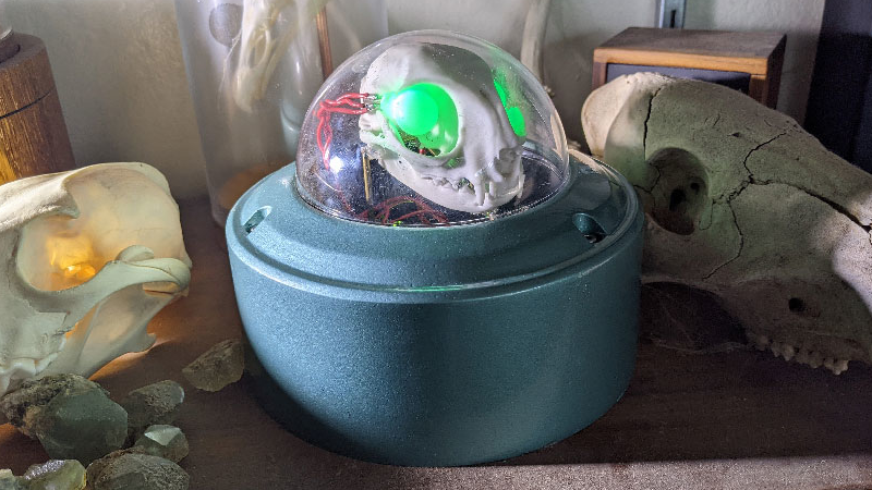
[Emily Velasco] has an internet provider that provides sub-par connectivity. Instead of repeatedly refreshing a browser tab to test if the network is up, [Emily] decided to create an internet status monitor by embedding indicator lights in a cat skull…for some reason.
The electronics are straightforward, with the complete parts list consisting of an Arduino Nano 33 IoT device connected to a pair of RGB LEDs and 50 Ohm resistors. The Nano attempts to connect to a known site (in this case, the Google landing page) every two seconds and sets the LEDs to green if it succeeds or red if it fails.
The cat skull is thankfully a replica, 3D printed by one of [Emily]’s Twitter acquaintances, and the whole project was housed in a domed security camera enclosure. [Emily] mounts the LEDs into the skull to create a “brain in a jar” effect.
3D printers have become a staple in most makerspaces these days, enabling hackers to rapidly produce simple mechanical prototypes without the need for a dedicated machine shop. We’ve seen many creative 3D designs here on Hackaday and [jegatheesan.soundarapandian’s] Baby MIT Cheetah Robot is no exception. You’ve undoubtedly seen MIT’s cheetah robot. Well, [jegatheesan’s] hack takes a personal spin on the cheetah robot and his results are pretty cool.
The body of the robot is 3D printed making it easy to customize the design and replace broken parts as you go. The legs are designed in a five-bar linkage with two servo motors controlling each of the four legs. An additional servo motor is used to rotate an HC-SR04, a popular ultrasonic distance sensor, used in the autonomous mode’s obstacle avoidance mechanism. The robot can also be controlled over Bluetooth using an app [jegatheesan] developed in MIT App Inventor.
Overall, the mechanics could use a bit of work — [jegatheesan’s] baby cheetah probably won’t outpace MIT’s robot any time soon — but it’s a cool hack and we’re looking forward to a version 3. Maybe the cheetah would make a cool companion bot?
We’re all familiar with the experience of buying hobby servos. The market is awash with cheap clones which have inflated specs and poor performance. Even branded servos often fail to deliver, and sometimes you just can’t get the required torque or speed from the small form factor of the typical hobby servo.
Enter [James Bruton] and his DIY RC servo from a windscreen wiper motor. Windscreen wiper motors are cheap as chips, and a classic salvage. The motor shaft is connected to a potentiometer via a pulley and some string, providing the necessary closed-loop feedback. Instead of using the traditional analog circuitry found inside a servo, an Arduino provides the brains. This means PID control can be implemented on the ‘duino, and tuned to get the best response from different load characteristics. There’s also the choice of different interfacing options: though [James]’ Arduino code accepts PWM signals for a drop-in R/C servo replacement, the addition of a microcontroller means many other input signal types and protocols are available. In fact, we recently wrote about serial bus servos and their numerous advantages.
We particularly love this because of the price barrier of industrial servomotors; sure, this kind of solution doesn’t have the precision or torque that off-the-shelf products provide, but would be sufficient for many hacks. Incidentally, this is what inspired one of our favourite open source projects: ODrive, which focuses on harnessing the power of cheap brushless motors for industrial use.
If you have OCD, then the worst thing someone could do is give you a bowl of multi-coloured M&M’s or Skittles — or Gems if you’re in the part of the world where this was written. The candies just won’t taste good until you’ve managed to sort them in to separate coloured heaps. And if you’re a hacker, you’ll obviously build a sorting machine to do the job for you.
Use our search box and you’ll find a long list of coverage describing all manner and kinds of sorting machines. And while all of them do their designated job, 19 year old [Willem Pennings]’s m&m and Skittle Sorting Machine is the bees knees. It’s one of the best builds we’ve seen to date, looking more like a Scandinavian Appliance than a DIY hack. He’s ratcheted up a 100k views on Youtube, 900k views on imgur and almost 2.5k comments on reddit, all within a day of posting the build details on his blog.
As quite often happens, his work is based on an earlier design, but he ends up adding lots of improvements to his version. It’s got a hopper at the top for loading either m&m’s or Skittles and six bowls at the bottom to receive the color sorted candies. The user interface is just two buttons — one to select between the two candy types and another to start the sorting. The hardware is all 3D printed and laser cut. But he’s put in extra effort to clean the laser cut pieces and paint them white to give it that neat, appliance look. The white, 3D printed parts add to the appeal.
Rotating the input funnel to prevent the candies from clogging the feed pipes is an ace idea. A WS2812 LED is placed above each bowl, lighting up the bowl where the next candy will be ejected and at the same time, a WS2812 strip around the periphery of the main body lights up with the color of the detected candy, making it a treat, literally, to watch this thing in action. His blog post has more details about the build, and the video after the break shows the awesome machine in action.
Imagine trying to make a ball-shaped robot that rolls in any direction but with a head that stays on. When I saw the BB-8 droid doing just that in the first Star Wars: The Force Awakens trailer, it was an interesting engineering challenge that I couldn’t resist. All the details for how I made it would fill a book, so here are the highlights: the problems I ran into, how I solved them and what I learned.
The Design Criteria: Portable and Inexpensive
Carrying BB-8
I had two design criteria in mind. The first was to keep it low-cost. Some spend $1000 to $1500 on their BB-8s. I wanted to spend as little as I could, so as many parts as possible had to come from my existing stock and from online classifieds and thrift stores. Not counting the parts that were discarded along the way, the cost came in just shy of $300.
The second design criteria was to make it portable. It had to be something I could take on the bus or carry while walking a reasonable distance (I once carried it twenty-five minutes to a nearby school).
Both of these criteria meant that it had to be smaller than full size. A full size ball is 20″ in diameter. Mine has a 12″ ball which makes it 3/5 scale. Also, the larger it is, the more powerful and costly the motors, batteries, motor controllers, magnets, and so on.
Version One: Quick And Easy
First I tried a minimalist approach. For the ball, I found my 12″ cardboard globe on kijiji.ca. I bought an RC toy truck at a yard sale and attached a pole to it for holding magnets near the top of the globe. I then made a head with corresponding magnets under it. The head magnets attract to the pole magnets, keeping the head on. Meanwhile, the truck rolling inside the ball makes the ball move.
Making the ball roll around was easy. Making it roll around while keeping the head on was very hard. The magnets at the top of the pole attract the magnets under the head, pulling them down hard onto the surface of the globe. That essentially glues the truck to the top of the globe.
To overcome that the truck needs sufficient traction. That also means the truck needs to be heavy. And lastly, the truck’s motor needs to be powerful enough to overcome its own weight and the grip of the magnets on the ball. The alternative is to make the magnetic attraction weaker, but if it’s too weak the head falls off. It’s a tricky balancing act, in both senses of the word.
But the most dome-like head I could make stay on was just a cardboard skeleton. Anything more filled out would be heavier and require a stronger magnetic attraction. The toy truck’s motor would not be up to it.
Version Two: Drill Motors And Drill Batteries
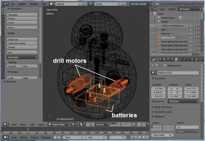
Batteries and motors in Blender
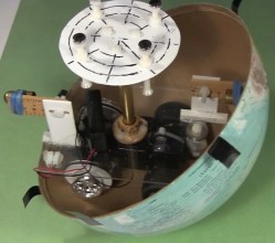
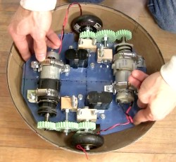
For more powerful motors and more mass I figured I could kill two birds with one stone by going with drill motors and drill batteries in a hamster drive configuration. Using drill parts kept costs down as the batteries and one drill came from yard sales while the other drill was free through freecycle.org. Meanwhile, both are heavy.
To make sure it all fit, I drew up a 3D model in Blender, the free 3D modelling and animation software that I use a lot. In fact, finding out how to make the batteries and motors fit was the first step. They had to be as low as possible. Their large mass low down is what keeps the droid vertical, with the much lighter head at the highest point.
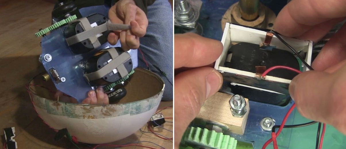
Batteries Velcroed and a connector
The drill batteries had to be easily removable for recharging. To hold them under the drive plate I simply used Velcro. Meanwhile, the drill battery stems went up through a hole in the drive plate. I made a connector to electrically connect to the battery terminals. It is a plastic rectangle with thin copper sheet metal for the contacts. Once the battery was Velcroed in place, this plastic and metal piece was lowered down onto the stem, the copper metal making contact with the battery terminals.
The Electronics
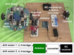
For the brains I used an Arduino UNO. To drive the motors I had all the parts for making two H-bridge driver boards, with the exception of 4 MOSFETs and some fuses. The Arduino does pulse width modulation (PWM) to the driver boards for speed control, as well as playing sounds at certain times when the motors are turned on.
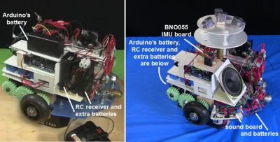
For remote control, I hacked the RC receiver from the toy truck and added an extra set of AA batteries in parallel for more runtime. A problem I ran into right away though, was that the RC receiver put out voltages of both polarities based on which direction the motors should rotate, whereas the Arduino’s pins take only positive voltages. To solve that I came up with a converter board to go between them.
Getting all that to work reliably took a while. Before I added fuses, I burned a few MOSFETs. At one point I’d put an N-type MOSFET where a P-type should have gone and vice versa. That resulting problem alone took a few days of spare time to figure out.
The wheels were old Rollerblade wheels — I keep a small bucket of these in my shop. I decided I wanted the ball to roll at around 1 foot per second and doing the math, that meant the wheels would have to rotate at around 2 rotations per second or 120 RPM. I found a PWM value that would give something close to that and started blowing fuses. I started with 1 amp fuses, then 2, 5, and finally settled on 10 amp fuses.
My final hurdle was that the motors would behave oddly when the motors were told to turn in opposite directions but were fine when they were told to turn in the same direction. This turned out to be a bad assumption on my part about how the RC receiver was wired internally — none of the output wires were common inside. After some changes to the circuit, I now had stable electronics.
I had basically been treating the RC receiver as a black box, but when I asked for help about my converter board here on Hackaday, it was pointed out that the receiver likely contained H bridges. Opening it up, that’s exactly what I found. The converter board works fine for now, but in the near further I’ll use one of the suggestions from that Hackaday post to eliminate the board altogether. I might even try all of the suggestions, just for fun.
The Drive System
The drive system
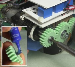
The motors were too long to fit in line between the wheels and so had to be mounted off to the sides. To transfer rotation to the wheels, I drew up some gears in Blender and 3D printed them at our local University of Ottawa Makerspace. In the print settings I used 2 shells and only 50% infill. The gears are held firmly onto the shafts solely using nuts and washers on either side. They’ve held up amazingly well, even with slipping and grinding during development.
For the bearings for the center gears and the wheels I used an old trick of making bearing blocks from hardwood.
Putting Loctite and screwing gear to motor shaft
I wanted to keep as much room as possible on the drive plate available for adding things later and so initially I’d mounted the motors at only three points. But this allowed the motors to move a little causing the gears to slip. To fix that I later added a fourth mounting point and haven’t had any slipping since.
At the end of the shaft for the drill motors is a hole that a screw goes into. That’s part of how the chuck is kept on a drill motor, and that’s how one gear was kept on. However, this screw had a tendency to get loose. Putting a little Loctite on the threads fixed that.
Stability
Rearranging BB-8’s internals
Given that I was trying to fit a lot in a small droid, I had to mount some things higher than I’d have liked to. When the droid stops, mass high up causes the droid to wobble. In the BB-8 droid used for promotional events they’ve gone to a great extent to keep the majority of the mass as low as possible. Originally I had the Arduino batteries and the RC receiver with its extra batteries fairly high up. I later mounted them much lower. When holding the internals in my hands I could tell the difference but it didn’t make a noticeable difference with the wobble.
Instead, for that I added Adafruit’s BNO055 inertial measurement unit (IMU) board. With it I could tell what angle the droid was at when stopping and experimented with PID loops and other algorithms of my own to minimize wobble. That helped.
The Ball
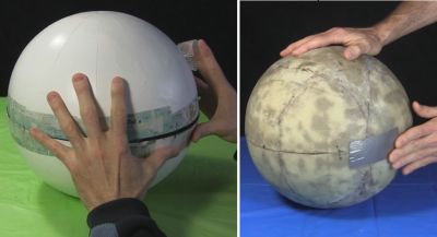
As I said, I used a 12″ cardboard globe. To increase the traction of the wheels inside the globe I sprayed the globe’s interior with an anti-slip spray from a hardware store. This made a huge difference. However, over time the anti-slip coating vanished, and so I’m looking for another, more permanent coating, perhaps urethane or something. If anyone has any suggestions, please let me know in the comments. It also has to stop off-gassing eventually. The anti-slip spray had an odor for a long time.
Sealing globes – cardboard and fiberglass
But the main problem with the cardboard globe was its thinness. With the huge weight of the internals pushing down on it where the wheels are, it warped significantly and required a lot of effort and a copious amount of tape to keep the two hemispheres together. This large amount of tape also made an uneven ridge for the head to slide over, making it get stuck. At that point either the drive system continued to move while the head fell off or the drive system couldn’t move at all.
The solution was to carefully coat a new globe in three layers of fiberglass. I took my time doing this, over a month and a half, applying one piece at a time and then sanding before putting the next piece. The result was a fantastic improvement. It no longer deformed and now it takes a minimal effort to attach the two hemispheres with only eight narrow strips of transparent duct tape.
The Never-ending Saga
My DIY BB-8 in action
My BB-8 is now at the point that I can call it finished. At least it’s finished as far as all the engineering is concerned, and that’s usually where I call it quits.
While the paint job worked out well, up close you can see that the details are painted on. It’d be nice to have at least the lines on the head be actual grooves. Also, these drill motors are brushed motors and I’ve since learned that doing high frequency PWM to brushed motors damages them over time. I’d like to replace them with brushless motors. And as anyone who’s use cordless drills a lot knows, drill batteries don’t last long, and so it’d be great to switch to LiPos.
But for now, the reactions I get from both kids and adults is beyond my wildest expectations. Kids threat it like a friend while adults have petted it and called to it like it was a baby or a dog wagging its tail. I’d call that a success.
[Stefan] works in a place where knowing the exact state of the foreign-exchange market is important to the money making schemes of the operation. Checking an app or a website was too slow and broke him out of his workflow. OS desktop widgets have more or less departed this earth for the moment. The only solution then, was to build a widget for his actual desk.
The brains of the device is a ESP8266 board, some peripherals and a small backlit TFT display. The device can run off battery or from a wall wart. [Stefan] even added some nice features not typically found in hacks like this, such as a photocell that detects the light level and dims the screen accordingly.
The software uses an interesting approach to get the latest times and timezones. Rather than use a chart or service made for the task, he uses an open weather API to do the task. Pretty clever.
The case is 3D printed and sanded. To get the nice finish shown in the picture [Stefan] spray-painted the case afterwards. All put together the device looks great and gives him the desktop widget he desired.


 The electronics are straightforward, with the complete parts list consisting of an Arduino Nano 33 IoT device connected to a pair of RGB LEDs and 50 Ohm resistors. The Nano attempts to connect to a known site (in this case, the Google landing page) every two seconds and sets the LEDs to green if it succeeds or red if it fails.