Posts with «esp8266» label

So Many Choices: Our Favorite Makers Weigh in on Their Go-To Dev Boards

Dev boards give makers limitless options for their projects. Some of our high-tech pals share their personal processes to pick a board.

The post So Many Choices: Our Favorite Makers Weigh in on Their Go-To Dev Boards appeared first on Make: DIY Projects and Ideas for Makers.

Great 8 character fluorescent (VFD) display

 In the process of expanding the family of supported displays for the WiFiChron clock, I found this amazing VFD module on aliexpress:

It has an SPI interface, it is powered by 5V, character set is defined and stored internally.

A quick search produced a sketch and documentation for the driver, PT6302.

According to the PCB silkscreen, the VFD module is powered by 5V, but the signals are 3V3. (The 30V required by the VFD glass itself is made by the on-board switching mode power supply, so no need to worry about generating high voltage externally.) An ESP32 board would be the perfect candidate to control this display. Luckily, the found sketch was also written for ESP32, so all I had to do was compile and upload using Arduino IDE 1.8.13. The only problem was that my IDE installation did not show ESP32 boards anymore, even though I used it once previously. Therefore, I had to re-visit the whole setup process once again. This time I am documenting it, to save on any future effort. So here are the steps:

  • install Arduino IDE (1.8.13, in my case) from Windows store, placed here:

  • add the ESP32/expressif package URL for the Boards Manager, as nicely explained here; essentially, select menu File -> Preferences, then add line
https://raw.githubusercontent.com/espressif/arduino-esp32/gh-pages/package_esp32_index.json
to input box "Additional Boards Manager URLs".
  • install the set of ESP32 boards in "Boards Manager"; menu Tools -> Boards Manager:
  • select the proper board for the ESP32-WROOM dev kit that I used; menu Tools -> Boards Manager -> ESP32 Arduino -> Node32s;
  • open the sketch, then modify the SPI pins (I used DIN=33, CLK=12, CS=13, RST=27, all on the same side of the ESP32 dev module); got compilation error "Library not found" for both NTPClient and TimeLib;
  • install the missing libraries, through menu Tools -> Manage Libraries...
The 2 libraries have been installed here
at the location specified in File -> Preferences:
  • compile, then upload successfully.
Surprisingly easy, straightforward and without glitches, this must have been the easiest ever first-time  interfacing with a device.

Compared to the HDSP-2534 LED display, the characters in the VFD module are about 50% bigger, and much brighter, making it readable from a greater distance. The current consumption is in the range 100-200mA, versus about 20mA taken by the HDSP display.


Also, at just about US$13, this (yet unnamed, or maybe Futaba?, see photo below) VFD display makes a great functional alternative for the more expensive HDSP/Avago/Siemens/Osram 8-character LED displays.


For the record, this was my setup:


And the (modified, barebone) sketch:
#include <WiFi.h>
#include <WiFiUdp.h>
#include <NTPClient.h>
#include <TimeLib.h>

WiFiUDP ntpUDP;
NTPClient timeClient(ntpUDP, "cn.ntp.org.cn", 8*3600, 60000);
const char *ssid = "<wifinet>";
const char *password = "<password>";

uint8_t din = 33; // DA
uint8_t clk = 12; //23; // CK
uint8_t cs = 13; //19; // CS
uint8_t Reset = 27; //22; // RS

char *str_time = "00:00:00";
String format_time = "00:00:00";

void write_6302(unsigned char w_data)
{
unsigned char i;
for (i = 0; i < 8; i++)
{
digitalWrite(clk, LOW);
if ( (w_data & 0x01) == 0x01)
{
digitalWrite(din, HIGH);
}
else
{
digitalWrite(din, LOW);
}
w_data >>= 1;
digitalWrite(clk, HIGH);
}
}

void VFD_cmd(unsigned char command)
{
digitalWrite(cs, LOW);
write_6302(command);
digitalWrite(cs, HIGH);
delayMicroseconds(5);
}

void S1201_show(void)
{
digitalWrite(cs, LOW);
write_6302(0xe8);
digitalWrite(cs, HIGH);
}

void VFD_init()
{
// set number of characters for display;
digitalWrite(cs, LOW);
write_6302(0xe0);
delayMicroseconds(5);
write_6302(0x07); // 8 chars;
digitalWrite(cs, HIGH);
delayMicroseconds(5);

// set brightness;
digitalWrite(cs, LOW);
write_6302(0xe4);
delayMicroseconds(5);
write_6302(0x33); // level 255 (max);
digitalWrite(cs, HIGH);
delayMicroseconds(5);
}

void S1201_WriteOneChar(unsigned char x, unsigned char chr)
{
digitalWrite(cs, LOW);
write_6302(0x20 + x);
write_6302(chr + 0x30);
digitalWrite(cs, HIGH);
S1201_show();
}

void S1201_WriteStr(unsigned char x, char *str)
{
digitalWrite(cs, LOW);
write_6302(0x20 + x);
while (*str)
{
write_6302(*str); // ascii
str++;
}
digitalWrite(cs, HIGH);
S1201_show();
}

void setup()
{
WiFi.begin(ssid, password);
Serial.begin(115200);
Serial.print("Connecting.");
while ( WiFi.status() != WL_CONNECTED ) {
delay(500);
Serial.print(".");
}
Serial.println("connected");

timeClient.begin();

pinMode(clk, OUTPUT);
pinMode(din, OUTPUT);
pinMode(cs, OUTPUT);
pinMode(Reset, OUTPUT);
digitalWrite(Reset, LOW);
delayMicroseconds(5);
digitalWrite(Reset, HIGH);
VFD_init();
}

void loop()
{
timeClient.update();
format_time = timeClient.getFormattedTime();
char *str_time = &format_time[0];
S1201_WriteStr(0, str_time);
Serial.println(timeClient.getFormattedTime());
delay(1000);
}


Next step should be researching the PT6302 command set, finding out how to adjust brightness and others.


LED Hourglass Moves Like the Real Thing

If you want to waste time in a meaningful way, get yourself an hourglass. It’s simultaneously mesmerizing and terrifying to sit there and watch the seconds slip through the threshold that separates possibility from missed opportunity.

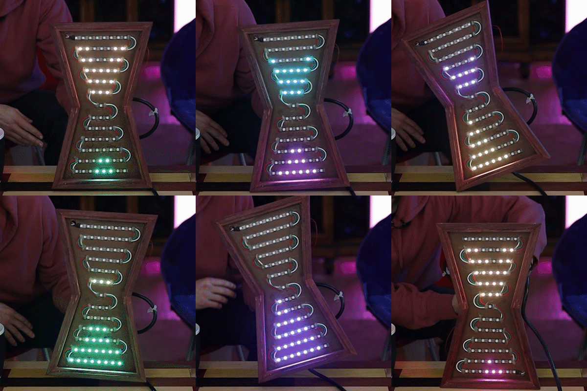
[Ty and Gig]’s LED hourglass is equally beautiful to watch. It doesn’t actually tell time, but that’s perfectly fine by us. What it does do is animate the LEDs to approximate grains of sand in gravity, no matter how the hourglass is tilted.

In either vertical orientation, the sand falls as long as there is some in the top. When the hourglass is horizontal, the LEDs settle just like real sand does. [Ty and Gig] achieved this with a whole lot of code that breaks the animation frames into structure arrays.

By contrast, the hardware part of this build is fairly simple: all that’s needed to replicate this build is some RGB LEDs a beefy power supply to drive them, an accelerometer, and a microcontroller.

[Ty and Gig] were planning to use an ESP8266, but misplaced it and went with an Arduino Mega instead. (You know what they say — buy a replacement and the one you lost will turn up almost immediately.) The beautiful frame is made from leftover purpleheart, a hardwood that turns purple with exposure to air. Check out the build video after the break.

Too lazy to reset your hourglass every hour? Here’s one that flips itself.

A Tiny LED Matrix is Better With Friends

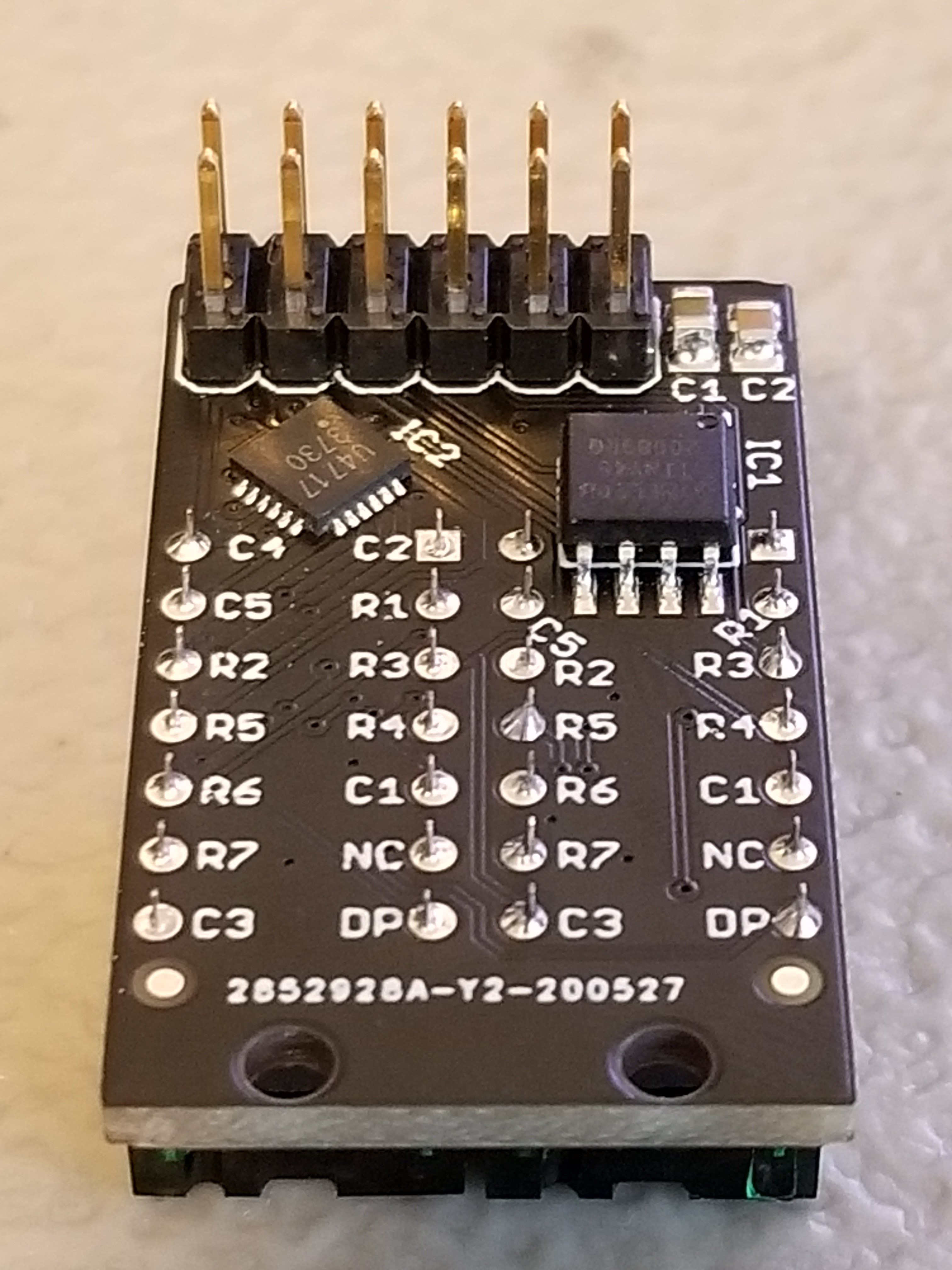
When we last heard from [lixielabs] he was building Nixie tube replacements out of etched acrylic and LEDs. Well he’s moved forward a few decades to bring us the Pixie, a chainable, addressable backpack for tiny LED matrix displays.

Each Pixie module is designed to host two gorgeous little Lite-On LTP-305G/HR 5×7 LED dot matrix displays, which we suspect have been impulse purchases in many a shopping cart. Along with the displays there is a small matrix controller and an ATTINY45 to expose a friendly electrical interface. Each module is designed to be mounted edge to edge and daisy chained out to 12 or more (with two displays each) for a flexible display any size you need. But to address the entire array only two control pins are required (data and clock).
[lixielabs] has done the legwork to make using those pins as easy as possible. He is careful to point out the importance of a good SDK and provides handy Arduino libraries for common microcontrollers and a reference implementation for the Raspberry Pi that should be easy to crib from to support new platforms. To go with that library support is superb documentation in the form of a datasheet (complete with dimensions and schematic!) and well stocked GitHub repo with examples and more.

To get a sense of their graphical capabilities, check out a video of 6 Pixie’s acting as a VU meter after the break. The Pixie looks like what you get when a hacker gets frustrated at reinventing LED dot matrix control for every project and decided to solve it once and for all. The design is clean, well documented, and extremely functional. We’re excited to see what comes next!

ESP32 with an I2S mic running FFT with 1024 cells, with each octave overlaid to make a 12-note chromagram, being rendered live by Pixies!https://t.co/0nWQfX0W6W pic.twitter.com/UZgh5ymWAw

— Lixie Labs (@lixielabs) September 22, 2020

Hex Matrix Clock is Spellbinding

Just when we think we’ve seen all possible combinations of 3D printing, microcontrollers, and pretty blinkenlights coming together to form DIY clocks, [Mukesh_Sankhla] goes and builds this geometric beauty. It’s kaleidoscopic, it’s mosaic, and it sorta resembles stained glass, but is way cheaper and easier.

The crucial part of the print does two jobs — it combines a plate full of holes for a string of addressable RGB LEDs with the light-dividing walls that turn the LEDs into triangular pixels. [Mukesh] designed digits for a clock that each use ten triangles. You’d need an ESP8266 to run the clock code, or if you’d rather sit and admire the rainbow light show unabated by the passing of time, just use an Arduino Uno or something similar.

Most of the aesthetic magic here is in the printed pieces and the FastLED library. It has a bunch of really cool animations baked in that look great with this design. Check out the demo video after the break. The audio is really quiet until the very end of the video, so be warned. In our opinion, the audio isn’t necessary to follow along with the build.

The humble clock takes many lovely forms around here, including pop art.

21st Century Cheating: WiFi In A Calculator

Obviously, we would never endorse cheating on an exam, but sometimes a device is just too tempting to be left untouched. For [Neutrino], it was an old Casio calculator that happened to have a perfectly sized solar panel to fit a 128×32 OLED as replacement. But since the display won’t do much on its own, he decided to connect it to an ESP8266 and mount it all inside the calculator’s housing, turning it into a spy-worthy, internet-connected cheating device, including a stealthy user interface controlled by magnets instead of physical buttons. (Video, embedded below.)

To achieve the latter, [Neutrino] added two Hall effect sensors and a reed switch inside each end of the calculator. Placing a magnet — possibly hidden in a pen cap — near the reed switch will turn the display on, and placing another magnet near the Hall-effect sensors will navigate through the display’s interface, supporting two inputs with long, short, and multi-tap gestures each. To obtain information through WiFi, the ESP8266 connects to Firebase as backend, allowing to set up predefined content to fetch, as well as a possibility to communicate with your partner(s) in crime through a simple chat program.

As the main idea was to keep visible modifications to a minimum, one shortcoming is that charging the additional battery that powers the whole system would require an additional, external charging circuit. But [Neutrino] had a solution for that as well, and simply exposed two wires to the back, which could easily be mistaken for random solder splatters. And well, of course, requiring WiFi might also be tricky in some situations, so maybe you might want to consider a mobile network upgrade for yourself.

Hack a Day 07 May 12:00

AvoRipe Takes A Firm Grip On The Ultimate First World Food Problem

You don’t have to be an extinct mammal or a Millennial to enjoy the smooth, buttery taste of an avocado. Being psychic on the other hand is definitely an advantage to catch that small, perfect window between raw and rotten of this divaesque fruit. But don’t worry, as modern problems require modern solutions, [Eden Bar-Tov], [Elan Goldberg], and [Mizpe Ramon] built the AvoRipe, a device to notify you when your next avocado has reached that window.

Taking both the firmness and color of an avocado as indicators of its ripeness into account, the team built a dome holding a TCS3200 color sensor as stand for the avocado itself, and 3D printed a servo-controlled gripper with a force sensor attached to it. Closing the gripper’s arms step by step and reading the force sensor’s value will determine the softness the avocado has reached. Using an ESP8266 as centerpiece, the AvoRipe is turned into a full-blown IoT device, reporting the sensor readings to a smartphone app, and collecting the avocado’s data history on an Adafruit.IO dashboard.

There is unfortunately one big drawback: to calibrate the sensors, a set of nicely, ripe avocados are required, turning the device into somewhat of a chicken and egg situation. Nevertheless, it’s a nice showcase of tying together different platforms available for widescale hobbyist projects. Sure, it doesn’t hurt to know how to do each part from scratch on your own, but on the other hand, why not use the shortcuts that are at our disposal to remove some obstacles — which sometimes might include programming itself.

Arduino IoT Cloud: Support for ESP8266 and other third party boards

With the latest release of Arduino IoT Cloud (version 0.8.0) we did a lot of work behind the scenes, and while it might be transparent to most users, it introduced some big changes. But the one we’re most excited about is that the Arduino IoT Cloud has begun supporting a number of third party devices.

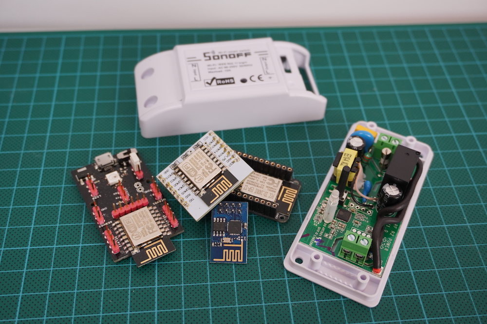
Starting with the uber-popular ESP8266 by Espressif — NodeMCU, Sparkfun’s ESP Thing, ESPDuino, and Wemos (to name a few) — along with other inexpensive commercially available plugs and switches based on this module. You can now add one to your Cloud Thing and control it using our intuitive web-based Dashboard.

Like every new release, there were plenty of obstacles to get around, especially providing security between the third party boards and the  Arduino IoT Cloud, where there’s no possibility to go through our secure certificate provisioning process because the hardware is lacking an essential component: the cryptographic element.

The Arduino IoT Cloud was born with security in mind and developed around the Arduino MKR series of boards featuring Microchip’s ATTECx08, an encryption chip capable of elliptic-curve cryptography. These boards store the bits necessary to authenticate with a server in a very secure way, guaranteeing your board is connecting to the real server and exchanging data over TLS.

When it comes to boards that don’t have enough RAM and do not feature such cryptographic elements, we had to enable a secondary way to get in. Data transfer will still be encrypted over SSL, but the server authentication part will be a little less strict, allowing the Arduino IoT Cloud to be available to a wider user base. Nevertheless, we do inform users that if they want the highest levels of security they’ll have to use a board which embeds a cryptographic chip. As more and more IoT device users become concerned with security, manufacturers are starting to implement such technologies. We have just recently seen standalone ECC modules which can be paired with your microcontroller of choice. It’s looking bright, and we’re proud to have been amongst the first to bring about this change.

For third party boards without a crypto chip, we had to extend our API and allow the creation of a device-exclusive unique identifier (which will be used as a username) and the generation of a Device Key, providing the final user to access the platform using a username: password pair. 

Internally we already used those tools and APIs; we’re just opening them up for use by a broader audience.

One small requirement for this to work is that you’ll need to upgrade your Arduino Create plan to the ‘Maker plan.’ This will give you access to ESP8266 compilation and IoT Cloud pairing of the device. The Maker plan will also extend the amount of original Arduino boards and Things you can create and manage.

This is just the first step in opening up to more and more hardware, and we have a lot of things lined up for our users. We really hope you’ll enjoy the ease of development and the tools to bring your application to the Cloud in the shortest possible time.

Head over to Arduino IoT Cloud and show us what you got!

A Farewell To YouTube Sub Counters Set To Break With API Change

Of all the things you never would have guessed you’d need just ten years ago, a YouTube subscriber counter would probably rank highly. You would have guessed that the little hits of dopamine accompanying each tick upward of a number would be so addictive?

As it turns out, lots of people wanted to keep a running total of their online fans, and a bewilderingly varied ecosystem of subscriber counters has cropped up. All of them rely on the API that YouTube exposes for such purposes, which as [Brian Lough] points out is about to change and break every subscription counter ever made. In the YouTube sub counter space, [Brian] is both an enabler – he built an Arduino wrapper to fetch YT sub counts easily – and a serial builder of displays for other YouTubers. The video below shows a collection of his work, many based on RGB LED matrix display, like the one used in his Tetris-themed sub counter. They’re all well-built, nice to look at, and sadly, destined for obsolescence sometime in August when the API changes.

The details of the API changes were made public in April, and for the subs count it amounts to rounding the count and displaying large counts as, for instance, 510k as opposed to 510,023. We’re confident that [Brian] and other display builders will be able to salvage some of their counters with code changes, but others will probably require hardware changes. Thanks, YouTube.

Hack a Day 02 Aug 03:00

Weather Station Can Rock You Like A Hurricane

People love to talk about the weather. It’s the perfect small talk, whether you’re trying to start a conversation or keep one going by avoiding an awkward silence. In the same fashion, weather stations are an ideal starting point for any sort of sensor-related project ideas. You get to familiarizing yourself with communication buses, ADCs, general data acquisition, and you learn a lot in figuring out how to visualize it all.

What if your weather station didn’t visualize anything? [OttoNL] is answering that question with a MIDI-generating Weather Station that uses the mood of the music to convey the condition of the elements outside.

Using an ESP8266 programmed via the Arduino IDE, [OttoNL] hooked up a light dependent resistor, a rain sensor, and the all-round workhorse BME280 for temperature, barometric pressure, and humidity to it. Reading the sensors, the ESP will generate MIDI notes that are sent to a connected synthesizer, with each sensor influencing a different aspect of the generated MIDI signals. A sadder, slow tune will play during rain and a fast upbeat one during sunshine. While it doesn’t use the ESP’s WiFi functionality at all at this point, a future version could easily retrieve some weather forecast data from the internet and add it into the mix as well.

Connect this to your alarm clock, and you can start your day off in the appropriate mood. You can even customize your breakfast toast to really immerse your morning routine in abstract weather cues.