Medication Reminder Uses Only One Button
As anyone who takes medicines regularly will attest to, the days have a tendency to blur together, making it hard to remember if you did something like take that day’s dose or not. There are plenty of products available to help keep track of medication reminders but many are overly complicated, so [Jeroen] built this one which keeps simplicity and usability as its core design principle.
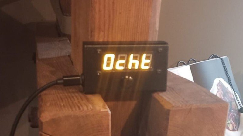
[Jeroen] calls it the MedMinder, and it’s a small, compact, rectangular device with a four-character display meant to sit on a countertop. When it’s time to take a medicine, the display will show that medicine’s four-letter code until the user pushes the single button under the display, signalling that they’ve taken their dose. If many different medications have to be taken at the same time, it displays the first priority until the button is pushed, and then displays whichever one is next after that.
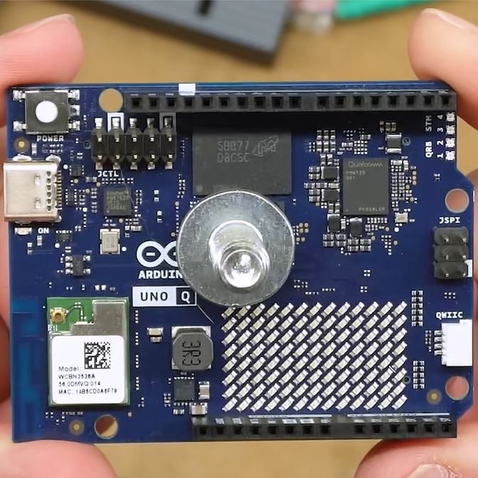
Programming is a little less straightforward, as the medications need to be added to the source code and uploaded to the Arduino that sits at the center of this build, but with the source code available this isn’t too difficult for someone with minimal experience with microcontrollers.
In an idealized world, technology should make our lives simpler or easier, and this small device goes a long way towards helping with that goal. Especially for an important but mundane task that can be surprisingly easy to lose track of. Although we glossed over the accuracy of this device’s clock in this article, we do have a comprehensive guide for selecting the right real-time clock for microcontrollers like this.