After Qualcomm’s purchase of Arduino it has left many wondering what market its new Uno Q board is trying to target. Taking the ongoing RAM-pocalypse as inspiration, [Bringus Studios] made a tongue-in-cheek video about using one of these SoC/MCU hybrid Arduino boards for running Linux and gaming on it. Naturally, with the lack of ARM-native Steam games, this meant using the FEX x86-to-ARM translator in addition to Steam’s Proton translation layer where no native Linux game exists, making for an excellent stress test of the SoC side of this board.
Technically, this is a heatsink. (Credit: Bringus Studios, YouTube)
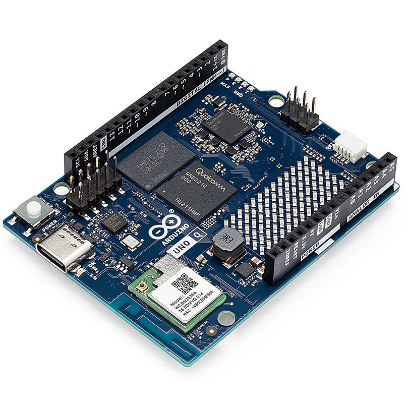
We covered this new ‘Arduino’ board previously, which features both a quad-core Cortex-A53 SoC and a Cortex-M33 MCU. Since it uses the Uno form factor, all SoC I/O goes via the single USB-C connector, meaning that a USB-C docking station is pretty much required to use the SoC, though there’s at least 16 GB of eMMC to install the OS on. A Debian-based OS image even comes preinstalled, which is convenient.
With a mere 2 GB of LPDDR4 it’s not the ideal board to run desktop Linux on, but if you’re persistent and patient enough it will work, and you can even play 3D video games as though it’s Qualcomm’s take on Raspberry Pi SBCs. After some intense gaming the SoC package gets really quite toasty, so adding a heatsink is probably needed if you want to peg its cores and GPU to 100% for extended periods of time.
As for dodging the RAM-pocalypse with one of these $44 boards, it’s about the same price as the 1 GB Raspberry Pi 5, but the 2 GB RPi 5 – even with the recent second price bump – is probably a better deal for this purpose. Especially since you can skip the whole docking station, but losing the eMMC is a rawer deal, and the dedicated MCU could be arguably nice for more dedicated purposes. Still, desktop performance is a hard ‘meh’ on the Uno Q, even if you’re very generous.
Despite FEX being a pain to set up, it seems to work well, which is promising for Valve’s upcoming Steam Frame VR glasses, which are incidentally Qualcomm Snapdragon-based.
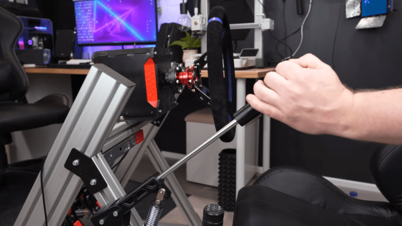
Simulator-style video games are designed to scale in complexity, allowing players to engage at anything from a casual level to highly detailed, realistic simulation. Microsoft Flight Simulator, for example, can be played with a keyboard and mouse, a controller, or a huge, expensive simulator designed to replicate a specific airplane in every detail. Driving simulators are similar, and [CNCDan] has been hard at work on his DIY immersive driving sim rig, with this hand brake as his latest addition.
For this build, [CNCDan] is going with a lever-style handbrake which is common in motorsports like drifting and rallying. He has already built a set of custom pedals, so this design borrows heavily from them. That means that the sensor is a load cell, which takes input force from a lever connected to it with a spring mechanism. The signal is sent to an Arduino for processing, which is set up to send data over USB like any joystick or controller. In this case, he’s using an Arduino that was already handling inputs from his custom shifter, so he only needed to use another input and add some code to get his handbrake added into his sim.
[CNCDan] built a version of this out of laser-cut metal parts, but also has a fully 3D printable one available as well. Plenty of his other videos about his driving rig are available as well, from the pedal assembly we mentioned earlier to the force-feedback steering wheel. It’s an impressive set of hardware with a feel that replicates racing about as faithfully as a simulator could. Interestingly, we’ve also seen this process in reverse as well where a real car was used instead as a video game controller.
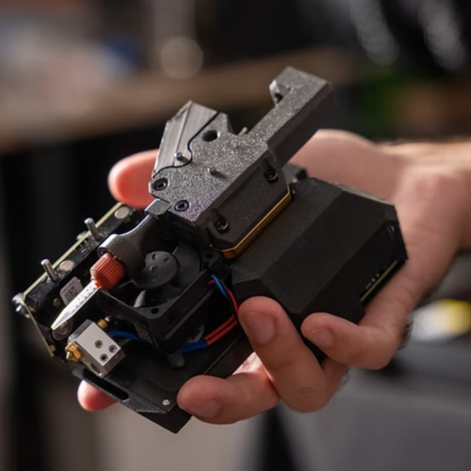
For a full-fledged, bells-and-whistles driving simulator a number of unique human interface devices are needed, from pedals and shifters to the steering wheel. These steering wheels often have force feedback, with a small motor inside that can provide resistance to a user’s input that feels the same way that a steering wheel on a real car would. Inexpensive or small joysticks often omit this feature, but [Jason] has figured out a way to bring this to even the smallest game controllers.
The mechanism at the center of his controller is a DC motor out of an inkjet printer. Inkjet printers have a lot of these motors paired with rotary encoders for precision control, which is exactly what is needed here. A rotary encoder can determine the precise position of the controller’s wheel, and the motor can provide an appropriate resistive force depending on what is going on in the game. The motors out of a printer aren’t plug-and-play, though. They also need an H-bridge so they can get driven in either direction, and the entire mechanism is connected to an Arduino in the base of the controller to easily communicate with a computer over USB.
In testing the controller does behave like its larger, more expensive cousins, providing feedback to the driver and showing that it’s ready for one’s racing game of choice. It’s an excellent project for those who are space-constrained or who like to game on the go, but if you have more space available you might also want to check out [Jason]’s larger version built from a power drill instead parts from an inkjet.
Famously, the save icon on most computer user interfaces references a fairly obsolete piece of technology: the venerable floppy disk. It’s likely that most people below the age of about 30 have never interacted with one of these once-ubiquitous storage devices, so much so that many don’t recognize the object within the save icon itself anymore. [Mads Chr. Olesen]’s kids might be an exception here, though, as he’s built a remote control for them that uses real floppy disks to select the programming on the TV.
This project partially began as a way to keep the children from turning into zombies as a result of the modern auto-play brainrot-based economies common in modern media. He wanted his kids to be able to make meaningful choices and then not get sucked into these types of systems. The floppy disk presents a perfect solution here. They’re tangible media and can actually store data, so he got to work interfacing a real floppy disk drive with a microcontroller. When a disk is inserted the microcontroller wakes up, reads the data, and then sends out a command to stream the relevant media to the Chromecast on the TV. When the disk is removed, the microcontroller stops play.
Like any remote, this one is battery powered as well, but running a microcontroller and floppy disk drive came with a few challenges. This one is powered by 18650 lithium cells to help with current peaks from the drive, and after working out a few kinks it works perfectly for [Mads] children. We’ve seen a few other floppy disk-based remote controls like this one which replaces the data stored on the magnetic disc with an RFID tag instead.
If you’re reading this, that means you’ve successfully made it through 2025! Allow us to be the first to congratulate you — that’s another twelve months of skills learned, projects started, and hacks….hacked. The average Hackaday reader has a thirst for knowledge and an insatiable appetite for new challenges, so we know you’re already eager to take on everything 2026 has to offer.
But before we step too far into the unknown, we’ve found that it helps to take a moment and reflect on where we’ve been. You know how the saying goes: those that don’t learn from history are doomed to repeat it. That whole impending doom bit obviously has a negative connotation, but we like to think the axiom applies for both the lows and highs in life. Sure you should avoid making the same mistake twice, but why not have another go at the stuff that worked? In fact, why not try to make it even better this time?
As such, it’s become a Hackaday tradition to rewind the clock and take a look at some of the most noteworthy stories and trends of the previous year, as seen from our rather unique viewpoint in the maker and hacker world. With a little luck, reviewing the lessons of 2025 can help us prosper in 2026 and beyond.
Love it or Hate it, AI is Here
While artificial intelligence software — or at least, what passes for it by current standards — has been part of the technical zeitgeist for a few years, 2026 was definitely the year that AI seemed to be everywhere. So much so that the folks at Merriam-Webster decided to make “slop”, as in computer-generated garbage content, their Word of the Year. They also gave honorable mention to “touch grass”, which they describe as a phrase that’s “often aimed at people who spend so much time online that they become disconnected from reality.” But we’re going to ignore that one for personal reasons.
At Hackaday, we’ve obviously got some strong feelings on AI. For those who earn a living by beating the written word into submission seven days a week, the rise of AI is nothing less than an existential crisis. The only thing we have going for us is the fact that the average Hackaday reader is sharp enough to recognize the danger posed by a future in which all of our media is produced by a Python script running on somebody’s graphics card and will continue to support us, warts and all.
Like all powerful tools, AI can get you into trouble if you aren’t careful.
But while most of us are on the same page about AI in regards to things like written articles or pieces of art, it’s not so clear cut when it comes to more utilitarian endeavours. There’s a not insignificant part of our community that’s very interested in having AI help out with tedious tasks such as writing code, or designing PCBs; and while the technology is still in its infancy, there’s no question the state of the art is evolving rapidly.
Make no mistake, an over-reliance on AI tools can be dangerous. In the best case, the user is deprived of the opportunity to actually learn the material at hand. In the worst case, you make an LLM-enhanced blunder that costs you time and money. But when used properly, the takeaway seems to be that a competent maker or hacker can leverage these new AI tools to help bring more of their projects across the finish line — and that’s something we’ve got a hard time being against.
Meshtastic Goes Mainstream
Another tech that gained steam this year is Meshtastic. This open source project aims to allow anyone to create an off-grid, decentralized, mesh network with low cost microcontrollers and radio modules. We fell in love with the idea as soon as we heard about it, as did many a hacker. But the project has reached a level of maturity that it’s starting to overflow into other communities, with the end result being a larger and more capable mesh that benefits everyone.
Part of the appeal is really how ridiculously cheap and easy it is to get started. If you’re starting from absolutely zero, connecting up to an existing mesh network — or creating your own — can cost you as little as $10 USD. But if you’re reading Hackaday, there’s a good chance you’ve already got a supported microcontroller (or 10) laying around, in which case you may just need to spring for the LoRa radio module and wire it up. Add a 3D printed case, and you’re meshin’ with the best of them.
There are turn-key Meshtastic options available for every budget, from beginner to enthusiast.
If you’re OK with trading some money for time, there’s a whole world of ready to go Meshtastic devices available online from places like Amazon, AliExpress, and even Etsy for that personal touch. Fans of the retro aesthetic would be hard pressed to find a more stylish way to get on the grid than the Hacker Pager, and if you joined us in Pasadena this year for Hackaday Supercon, you even got to take home a capable Meshtastic device in the form of the Communicator Badge.
Whether you’re looking for a backup communication network in the event of a natural disaster, want to chat with neighbors without a megacorp snooping on your discussion, or are simply curious about radio communications, Meshtastic is a fantastic project to get involved with. If you haven’t taken the plunge already, point your antenna to the sky and see who’s out there, you might be surprised at what you find.
Arduino’s New Overlord
In terms of headlines, the acquisition of Arduino by Qualcomm was a pretty big one for our community. Many a breathless article was written about what this meant for the future of the company. And things only got more frantic a month later, when the new Arduino lawyers updated the website’s Terms and Conditions.
But you didn’t see any articles about that here on Hackaday. The most interesting part of the whole thing to us was the new Arduino Uno Q: an under $50 USD single-board computer that can run Linux while retaining the classic Uno layout. With the cost of Raspberry Pi hardware steadily increasing over the years, some competition on the lower end of the price spectrum is good for everyone.
The Arduino Uno Q packs enough punch to run Linux.
As for the Qualcomm situation — we’re hackers, not lawyers. Our immediate impression of the new ToS changes was that they only applied to the company’s web services — “The Platform” in the contract — and had no bearing on the core Arduino software and hardware offerings that we’re all familiar with. The company eventually released a blog post explaining more or less the same thing, explaining that evolving privacy requirements for online services meant they had to codify certain best practices, and that their commitment to open source is unwavering.
For now, that’s good enough for us. But the whole debacle does bring to mind a question: if future Arduino software development went closed-source tomorrow, how much of an impact would it really have on the community at this point? Today when somebody talks about doing something with Arduino they are more likely to be talking about the IDE and development environment than one of the company’s microcontroller boards — the licenses for which mean the versions we have now will remain open in perpetuity. The old AVR Arduino code is GPLed, after all, as are the newer cores for microcontrollers like the ESP32 and RP2040, which weren’t written by Arduino anyway. On the software side, we believe that we have nothing to lose.
But Arduino products have also always been open hardware, and we’ve all gained a lot from that. This is where Qualcomm could still upset the applecart, but we don’t see why they would, and they say they won’t. We’ll see in 2026.
The Year of Not-Windows on the Desktop?
The “Year of Linux on the Desktop” is a bit like fusion power, in that no matter how many technical hurdles are cleared, it seems to be perennially just over the horizon. At this point it’s become a meme, so we won’t do the cliché thing and claim that 2025 (or even 2026) is going to finally be the year when Linux breaks out of the server room and becomes a mainstream desktop operating system. But it does seem like something is starting to shift.
That’s due, at least in part, to Microsoft managing to bungle the job so badly with their Windows 11 strategy. In spite of considerable push-back in the tech community over various aspects of the operating system, the Redmond software giant seems hell-bent on getting users upgraded. At the same time, making it a hard requirement that all Windows 11 machines have a Trusted Platform Module means that millions of otherwise perfectly usable computers are left out in the cold.
What we’re left with is a whole lot of folks who either are unwilling, or unable, to run Microsoft’s latest operating system. At the same time desktop Linux has never been more accessible, and thanks in large part to the efforts of Valve, it can now run the majority of popular Windows games. That last bit might not seem terribly exciting to folks in our circles, but historically, the difficulty involved in playing AAA games on Linux has kept many a techie from making the switch.
Does that mean everyone is switching over to Linux? Well, no. Certainly Linux is seeing an influx of new users, but for the average person, it’s more likely they’d switch to Mac or pick up a cheap Chromebook if all they want to do is surf the web and use social media.
Of course, there’s an argument to be made that Chromebook users are technically Linux users, even if they don’t know it. But for that matter, you could say anyone running macOS is a BSD user. In that case, perhaps the “Year of *nix” might actually be nigh.
Grandma is 3D Printing in Color
There was a time when desktop 3D printers were made of laser-cut wood, used literal strings instead of belts, and more often then not, came as a kit you had to assemble with whatever assistance you could scrounge up from message boards and IRC channels — and we liked it that way. A few years later, printers were made out of metal and became more reliable, and within a decade or so you could get something like an Ender 3 for a couple hundred bucks on Amazon that more or less worked out of the box. We figured that was as mainstream as 3D printing was likely to get…but we were very wrong.
A Prusa hotend capable of printing a two-part liquid silicone.
Today 3D printing is approaching a point where the act of downloading a model, slicing it, and manifesting it into physical form has become, dare we say it, mundane. While we’re not always thrilled with the companies that make them and their approach to things that are important to us like repairability, open development, and privacy, we have to admit that the new breed of printers on the market today are damn good at what they do. Features like automatic calibration and filament run-out sensors, once the sort of capabilities you’d only see on eye-wateringly expensive prosumer machines, have became standard equipment.
Desktop 3D printing still hasn’t reached the sort of widespread adoption that all those early investors would have had us believe in the 2000s, where every home would one day have their own Star Trek style personal replicator. But they are arguably approaching the commonality of something like a table saw or drill press — specialized but affordable and reliable tools that act as a force multiplier rather than a tinkerer’s time sink.
Tariffs Take Their Toll
Finally, we couldn’t end an overview of 2025 without at least mentioning the ongoing tariff situation in the United States. While it hasn’t ground DIY electronics to a halt as some might have feared, it’s certainly had an impact.
A tax on imported components is nothing new. We first ran into that back in 2018, and though it was an annoyance, it didn’t have too much of an impact at the hobbyist scale. When an LED costs 20 cents, even a 100% tariff wouldn’t be much of a hit to the wallet at the scale most of us are operating at. Plus there are domestic, or at least non-Chinese, options for some jellybean components. The surplus market can also help here — you can often find great deals on things like partial reels of SMD capacitors and resistors on eBay if you keep an eye out for them.
We’ve heard more complaints about PCB production than anything. After years of being able to get boards made overseas for literal pennies, seeing a import tax that added at checkout can be quite a shock. But just like the added tax on components, while annoying, it’s not enough to actually keep folks from ordering. Even with the tariffs, the cost of getting a PCB made at OSH Park is going to be much higher than any Chinese board house.
Truth be told, if an import tax on Chinese-made PCBs and components resulted in a boom of affordable domestic alternatives, we’d be all over it. The idea that our little hobby boards needed to cross an ocean just to get to us always seemed unsustainable anyway. It wouldn’t even have to be domestic, there’s an opportunity for countries with a lower import tariff to step in. Instead of having our boards made in China, why not India or Mexico?
But unfortunately, the real-world is more complex than that. Building up those capabilities, either at home or abroad, takes time and money. So while we’d love to see this situation lead to greater competition, we’ve got a feeling that the end result is just more money out of our pockets.
Thanks for Another Year of Hacks
One thing that absolutely didn’t change in 2025 was you — thanks to everyone that makes Hackaday part of their daily routine, we’ve been able to keep the lights on for another year. Everyone here knows how incredibly fortunate we are to have this opportunity, and your ongoing support is never taken for granted.
We’d love to hear what you thought the biggest stories or trends of 2025 were, good and bad. Let us know what lessons you’ll be taking with you into 2026 down below in the comments.
In a curious historical twist, the “Twelve days of Christmas” are actually the days of revelry that followed the 25th. The preceding period, Advent, was traditionally a fast, not unlike Lent. When and why a fast became an excuse for chocolate calendars we cannot say, but this historical information is presented to explain that this great hack by [Kevin], making a vintage speech synthesizer chip sing the classic carol will remain relevant at least until January 5th — or perhaps even the 19th, for the Orthodox amongst us.
The chip in question is an SP0256A-AL2, which you may remember from various speech projects for 8-bit computers back in the day. It can talk, after a fashion, by reproducing 56 “allophones” — the sounds that make up English speech — from ROM. Singing, though? We cannot recall much of that back in the day, but then, a talking computer was impressive enough.
As it turns out this is building on an earlier hack [Kevin] did in which he used an Arduino to make the venerable speech chip MIDI controllable. In that project’s write-up it is revealed that a Si5351 programmable clock module is used to give a variable pitch signal to the speech synthesizer. In this way he’s able to get about an octave an a half, which is good enough when the carol in question only spans one octave.
Of course the pitch signal needs to be varied by something and for that the venerable Arduino once again takes the place of an 8-bit computer. In this case it’s pre-programmed, but can also be set up for MIDI control.Of course nothing says you can’t use true retro hardware or a more-capable RP2040 instead of the Amtel chip.
It’s sad to think how much compute power has been wasted this year on AI-generated novelty carols when a little bit of 1980s silicon and some ingenuity can do nearly as good — or better, depending on your tastes.
[Rick] had a problem. His garage refrigerator was tasked with a critical duty—keeping refreshing beverages at low temperature. Unfortunately, it had failed—the condenser was forever running, or not running at all. The beverages were either frozen, or lukewarm, regardless of the thermostat setting. There was nothing for it—the controller had to be rebuilt from scratch.
Thankfully, [Rick]’s junk drawer was obliging. He was able to find an Arduino Uno R4, complete with WiFi connectivity courtesy of the ESP32 microcontroller onboard. This was paired with a DHT11 sensor, which provided temperature and humidity measurements. [Rick] began testing the hardware by spitting out temperature readings on the Uno’s LED matrix.
Once that was working, the microcontroller had to be given control over the fridge itself. This was achieved by programming it to activate a Kasa brand smart plug, which could switch mains power to the fridge as needed. The Uno simply emulated the action of the Kasa phone app to switch the smart plug on and off to control the fridge’s temperature, with the fridge essentially running flat out whenever it was switched on. The Uno also logs temperature to a server so [Rick] can make sure temperatures remain in the proper range.
Want to know if somebody is lying? It’s always so hard to tell. [dbmaking] has whipped up a fun little polygraph, otherwise known as a lie detector. It’s nowhere near as complex as the ones you’ve seen on TV, but it might be just as good when it comes to finding the truth.
The project keeps things simple by focusing on two major biometric readouts — heart rate and skin conductivity. When it comes to the beating heart, [dbmaking] went hardcore and chose an AD8232 ECG device, rather than relying on the crutch that is pulse oximetry. It picks up heart signals via three leads that are just like those they stick on you in the emergency room. Skin conductivity is measured with a pair of electrodes that attach to the fingers with Velcro straps. The readings from these inputs are measured and then used to determine truth or a lie if their values cross a certain threshold. Presumably, if you’re sweating a lot and your heart is beating like crazy, you’re telling a lie. After all, we know Olympic sprinters never tell the truth immediately after a run.
Does this work as an actual, viable lie detector? No, not really. But that’s not just because this device isn’t sophisticated enough; commercial polygraph systems have been widely discredited anyway. There simply isn’t an easy way to correlate sweating to lying, as much as TV has told us the opposite. Consider it a fun toy or prop to play with, and a great way to learn about working with microcontrollers and biometric sensors.
If you’ve got an old black and white TV, it’s probably not useful for much. There are precious few analog broadcasters left in the world and black and white isn’t that fun to watch, anyway. However, with a little work, you could repurpose that old tube as a clock, as [mircemk] demonstrates.
The build is based around an Arduino Nano R3. This isn’t a particularly powerful microcontroller board, but it’s good enough to run the classic TVOut library. This library lets you generate composite video on an Atmel AVR microcontroller with an absolute minimum of supporting circuitry. [mircemk] paired the Arduino with a DS3231 real-time clock, and whipped up code to display the time and date on the composite video output. He then also demonstrates how to hack the signal into an old TV that doesn’t have a specific input for composite signals.
You’ll note the headline says “any old TV can be a clock,” and that’s for good reason. Newer TVs tend to eschew the classic composite video input, so the TVOut library won’t be any good if you’re trying to get a display up on your modern-era flatscreen. In any case, we’ve seen the TVOut library put to good use before, too. Video after the break.
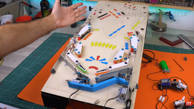
Pinball machines have something for everyone. They’re engaging, fast-paced games available in a variety of sizes and difficulties, and legend has it that they can be played even while deaf and blind. Wizardry aside, pinball machines have a lot to offer those of us around here as well, as they’re a complex mix of analog and digital components, games, computers, and artistry. [Daniele Tartaglia] is showing off every one of his skills to build a tabletop pinball machine completely from the ground up.
This is the latest in a series of videos documenting [Daniele]’s project, so he already has the general arrangement of the game set up. He has some improved ball-counting devices to enhance the game’s ability to keep track of ball position. [Daniele] also builds a few chutes and chimneys for the ball to pass outside of the play field. Next up are flippers and some of the bumpers. The video is rounded out with conductive targets built completely from scratch using metal zip ties. With a machine as complex as this, there are many points during the build where he has to stop and redesign parts. Prototyping as he goes, [Daniele] adds to the distinctive flair of this unique game.
This build truly puts every tool in [Daniele]’s toolbox to work, from a laser cutter, lathe, and 3D printer to various microcontrollers, solenoids, and electronics. He seamlessly blends the analog world of steel ball bearings and rubber bumpers with the digital world of scoring, automation, lighting, and sound. Pinball machines are experiencing a bit of a resurgence, meaning many of the classic tables are expensive collector’s items. If you want to build your own, we featured a great resource for others like [Daniele] who want to build one of these intricate machines themselves.