Posts with «infrared» label

IR Remote Tester Helps You Crack the Code

Even though some devices now use WiFi and Bluetooth, so much of our home entertainment equipment still relies on its own proprietary infrared remote control. By and large (when you can find them) they work fine, but what happens when they stop working?  First port of call is to change the batteries, of course, but once you’ve tried that what do you do next? [Hulk] has your back with this simple but effective IR Remote Tester / Decoder.

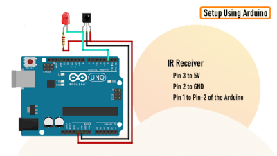
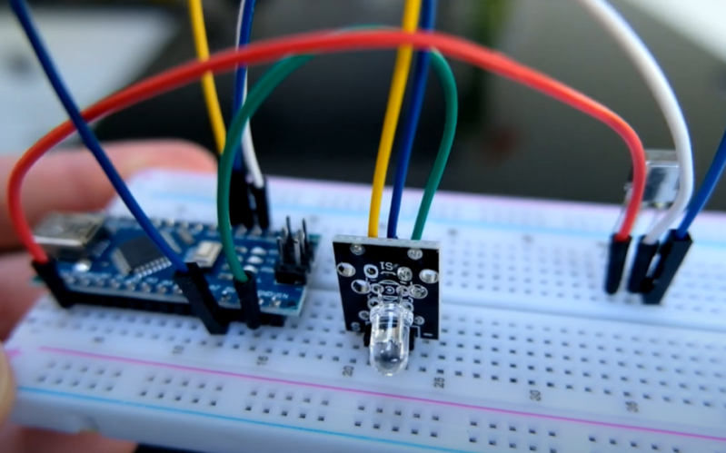
How to connect the TSOP4838 to an Arduino to read the transmitted codes

By using a cheap integrated IR receiver/decoder device (the venerable TSOP4838), most of the hard work is done for you! For a quick visual check that your remote is sending codes, it can easily drive a visible LED with just a resistor for a current-limit, and a capacitor to make the flickering easier to see.

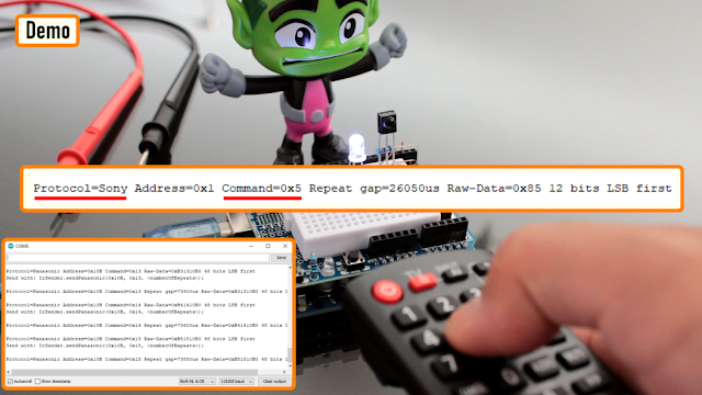
For an encore, [Hulk] shows how to connect this up to an Arduino and how to use the “IRremote” library to see the actual data being transmitted when the buttons are pressed.

It’s not much of a leap to imagine what else you might be able to do with this information once you’ve received it – controlling your own projects, cloning the IR remote codes, automating remote control sequences etc..

It’s a great way to make the invisible visible and add some helpful debug information into the mix.

We recently covered a more complex IR cloner, and if you need  to put together a truly universal remote control, then this project may be just what you need.

IR Translator Makes Truly Universal Remote

Universal remotes are a handy tool to have around if you have many devices that would all otherwise have their own remote controls. Merging them all into a single device leads to less clutter and less frustration, but they are often not truly “universal” as some of them may not support every infrared device that has ever been built. If you’re in a situation like that it’s possible to build a truly universal remote instead, provided you have a microcontroller and a few infrared LEDs on hand.

This was the situation that [Matt] found himself in when his Amazon Fire TV equipment control feature didn’t support his model of speakers. To get around this he programmed an Arduino to essentially translate the IR codes from the remote and output a compatible set of codes to the speakers.This requires both an IR photodiode and an IR LED but little else other than the codes for the remote and the equipment in question. With that all set up and programmed into the Aruino, [Matt]’s remote is one step closer to being truly “universal”.

While [Matt] was able to make use of existing codes in the Arduino library, it is also possible to capture the codes required manually by pointing a remote at a photodiode and programming a microcontroller to capture the codes that you need. [Matt] used a Raspberry Pi to do this when debugging this project, but we’ve also seen this method used with a similar build which uses an ESP8266 to control an air conditioner via its infrared remote control capabilities.

Universal Remote a Grove Infrared project


Description

This project will convert an ordinary Keyes infra-red (IR) remote
into a programmable universal remote.

 
A single button press on the Keyes remote will be converted into precise Sony IR signal combinations using an Arduino UNO and an assortment of Seeedstudio Grove modules.
You can assign signal combinations from more than one remote if desired.
An example combination could be to:
  • Turn on the TV and then switch channels.
  • Turn on the TV, sound system, and air-conditioner.
  • Turn up the volume x 3.
With only one button press of the Keyes remote, the entire cascade of Sony signals ensues. This project can be customised for other IR methodologies, however, you may have to modify the Arduino code to accommodate them.


Parts Required

  1. Arduino Uno (or compatible board)
  2. Grove Base Shield (v2)
  3. Grove Infrared Receiver
  4. Grove Infrared Emitter
  5. Grove Button
  6. Grove 16x2 LCD (White on Blue)
  7. Grove Universal 4 pin buckled cable: one supplied with each module.
  8. KEYES IR Remote Control
  9. SONY IR remote control
  10. USB cable - to power and program the Arduino
  11. Battery pack / Power bank


More information about the Grove modules can be found here:

**Please Note: The Grove Base shield has 14 pins on the Analog side, and 18 pins on the digital side. Check the number of pins on your Arduino UNO (or compatible board) to ensure the shield will sit nicely on top. NOT compatible with Arduino boards that have the Arduino Duemilanove pin header layout.


Arduino IDE

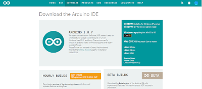
While there are many Arduino IDE alternatives out there, I would recommend that you use the official Arduino IDE for this project. I used the official Arduino IDE app (v1.8.5) for Windows 10.
Make sure to get the most up-to-date version for your operating system here.


Libraries required

The following libraries will be used in the Arduino code:

  1. Wire Library
  2. IRLib2 Library
  3. rgb_lcd Library

Wire Library

The Wire library is used for I2C communication for the Grove LCD screen and is built into the Arduino IDE - no additional download required for this library.
 

IRLib2 Library

The IRLib2 Library is actually a "set" of IR libraries, which can be downloaded from GitHub - here. In this project, I will be transmitting and receiving NEC and Sony IR remote signals.
The required libraries (within the set) will be:
  • IRLibRecv.h
  • IRLibDecodeBase.h
  • IRLibSendBase.h
  • IRLib_P01_NEC.h
  • IRLib_P02_Sony.h
  • IRLibCombo.h
Please see the IRLib2 GitHub Page for installation instructions.
 

rgb_lcd Library

The rgb_lcd.h library simplifies the operation of the LCD screen.
Download the rgb_lcd.h library from GitHub. Install the rgb_lcd.h library ZIP file into the Arduino IDE:
  1. Load the Arduino IDE
  2. Navigate to Sketch >Include library > Add .ZIP library...
  3. Select the downloaded zip file from GitHub, and press the "Open" button
  4. Check that it installed correctly by navigating to File > Examples > Grove-LCD RGB Backlight


Arduino Code

It is always best to upload the Arduino code to the board before you make any of the connections. This way you prevent the Arduino from sending current to a component accidentally. The code is available on my GitHub repository. Or you can have a look below. This code was written for an Arduino UNO, and may need to be modified if you are using a different board.


Connection instructions

If you are using the Grove Base Shield (v2). The connections are extremely simple. Use the following table as a guide. Please note that the code above assumes the following connections.


As per the table above, you would use a Grove universal 4-pin buckled cable and connect one side to D2 on the Grove base shield, and the other side would connect to the Grove Infrared Emitter.
D3 on the base shield would connect to the Grove Infrared Receiver, and so on.
You can connect the 16x2 LCD module to ANY of the four I2C connectors on the Grove base shield.

If you do not have a Grove Base shield, you have the option to use female-to-male jumper wires (together with a breadboard). But it is easier just to get the base shield and use the universal connectors.


Project Explained

When you apply power to the Arduino, the first thing that appears on the LCD screen is:


After pressing the Grove button (connected to D5), it displays the following message:


This is the cue to press and send a signal from the Keyes remote to the Infrared receiver (which is connected to D2). The Arduino will decode the Keyes remote signal, store the value in an array, and display the signal briefly on the LCD. The LCD should now show a message:


This message is a cue to press and send the FIRST signal from the Sony remote to the Infrared receiver. The Arduino will decode and store the Sony remote signal in a different array, and display it briefly on the LCD. You have the option to send a maximum of THREE Sony signal combinations to the Infrared receiver at this step in the process. The minimum number of Sony signals you can send is zero. The way to tell the Arduino that you do not want to send any further Sony signals to the receiver in this step, is by pressing the Grove Button (connected to D5).
 
The Arduino is programmed to receive a total of 5 Keyes signals, and each signal can be paired with a maximum of 3 Sony signal combinations. Once you have recorded all of the signal combinations, you will get a message:


The Arduino will now enter the final "Universal remote mode". In this mode, it will listen out for ANY of the 5 Keyes IR remote signals recorded previously, and will send the associated Sony signal combination in return. For example, if you press the number 1 on the Keyes remote, you could potentially have it so that the Arduino will transmit a Sony signal combination to turn on the TV and jump to a specific channnel.
 
The LCD will display each of the signals being transmitted. You will know you are in "Universal remote" mode because the LCD will display:


While you may be tempted to throw your Sony remote away at this stage (because you no longer have a use for it)... I would hold on to it just in case. The signals are not stored permanently. They disappear when the Arduino is powered off. But it doesn't have to be that way. You can easily modify the code to store it in eeprom memory or something.
 
That is not the only thing you can change.Technically, you could record the signal for any remote, however, you may need to include additional libraries or code to accommodate the alternate remote symbology. You can also modify the text messages on the LCD screen to make more sense to you. The LCD can only display 16 characters per row. So keep that it mind, when you come up with creative captions.
 
I would also like to mention the reason I chose not to use Seeedstudio's IR library, was because it took up too much memory. Their library probably accommodates for a wide range of symbologies. I chose the IRLib2 Library because I could select only the symbologies that I used (Sony and NEC). Thereby reducing the total amount of memory necessary to run the project. In fact, I have been finding that many of Seeedstudio's libraries to be very memory hungry. I originally wanted to create a gesture controlled remote. But the library combinations eliminated that possibility due to the cumulative memory requirements.


Conclusion

The IRLib2 library is the key to the success of this project. Without that library, this project would have been ten times harder. I was quite amazed by the effectiveness of this record / playback technique. It felt very weird to be operating my SONY TV with a cheap and nasty Keyes remote. It was quite surreal. While I chose to control my TV in this way, I could have just as easily recorded signals from one of my other remotes that use infrared signals. As more and more devices become controllable by remotes, the more I will consider turning this project into a permanent fixture in my house. A gesture controlled remote would have been nice, however, it looks like I will have to find some other use for that module now.

If you found this tutorial helpful, please consider supporting me by buying me a virtual coffee/beer.

$3.00 AUD only
 

Social Media

You can find me on various social networks:

Follow me on Twitter: ScottC @ArduinoBasics.
I can also be found on Instagram, Pinterest, and YouTube.
And if all else fails, I have a server on Discord.


Arduino Nano turned into universal IR translator

After purchasing a new television, maker Andreas Spiess’ remote no longer worked seamlessly with the controller his family had been using. While a universal remote could have solved the problem, in order to keep things simple to use, he instead came up with an infrared “babel fish” signal translator—named after the language translation animal Hitchhiker’s Guide to the Galaxy’s.

The device receives infrared signals from the original remote, then uses an Arduino Nano to pass the properly translated pulses on to his TV and receiver. A 3W IR diode transmits these new signals with the help of an N-channel MOSFET, giving it enough power to control each component, even without the proper line-of-sight orientation. 

It’s a hack that could be useful in many situations, and Speiss goes over how it was made, along with design requirements in the video below.

Tachometer Uses Light, Arduinos

To measure how fast something spins, most of us will reach for a tachometer without thinking much about how it works. Tachometers are often found in cars to measure engine RPM, but handheld units can be used for measuring the speed of rotation for other things as well. While some have mechanical shafts that must make physical contact with whatever you’re trying to measure, [electronoobs] has created a contactless tachometer that uses infrared light to take RPM measurements instead.

The tool uses an infrared emitter/detector pair along with an op amp to sense revolution speed. The signal from the IR detector is passed through an op amp in order to improve the quality of the signal and then that is fed into an Arduino. The device also features an OLED screen and a fine-tuning potentiometer all within its own self-contained, 3D-printed case and is powered by a 9 V battery, and can measure up to 10,000 RPM.

The only downside to this design is that a piece of white tape needs to be applied to the subject in order to get the IR detector to work properly, but this is an acceptable tradeoff for not having to make physical contact with a high-speed rotating shaft. All of the schematics and G code are available on the project site too if you want to build your own, and if you’re curious as to what other tools Arduinos have been used in be sure to check out the Arduino-based precision jig.

A Concept for a Robot that I am planning to build

A Concept for a Robot that I am planning to build

Pedal a Bike Through Virtual Reality for Under $100

Riding your bike on winter roads can be tough sometimes. Riding your bike through a virtual reality is easier and surprisingly affordable!

Read more on MAKE

The post Pedal a Bike Through Virtual Reality for Under $100 appeared first on Make: DIY Projects, How-Tos, Electronics, Crafts and Ideas for Makers.

Man Shoots Lamp

What do you get when you mix together all of the stuff that you can get for cheap over eBay with a bit of creativity and some PVC pipe? [Austiwawa] gets a table lamp, remote-controlled by a toy gun, that turns off and falls over when you shoot it. You’ve got to watch the video below the break.

This isn’t a technical hack. Rather it’s a creative use of a bunch of easily available parts, with a little cutting here and snipping there to make it work. For instance, [Austiwawa] took a remote control sender and receiver pair straight off the rack and soldered some wires to extend the LED and fit it inside the toy gun. A relay module controls the lamp, and plugs straight into the Arduino that’s behind everything. Plug and play.

Which is not to say the lamp lacks finesse. We especially like the screw used as an end-of-travel stop for the servo motor, and the nicely fabricated servo bracket made from two Ls. And you can’t beat the fall-over-dead effect. Or can you? Seriously, though, great project [Austiwawa]!


Filed under: home hacks

Slap my zombie hand for internet fame!

Halloween time is a great moment to explore nice interactive projects and get inspired for installations for other selfie occasions. To spice up the office Donnie Plumly, a creative technologist, decided to make and share with us a molded zombie arm that takes pictures and post them to Twitter.

He used a silicone arm (molded on his own hand ), a custom steel mount to clip to an office partition, and a vibration sensor hooked up to an Arduino Uno. Once the arm is slapped a photo will be taken using an IR Led and passed to the Eye-Fi card in the camera.

The photo is then saved into a Dropbox folder and, using If This Then That (IFTTT), posted to Twitter on the account @ZombieSelfie.

Donnie created also a very useful tutorial  on Instructable to make it yourself!