Posts with «pic» label

Simulate PIC and Arduino/AVR Designs with no Cloud

I’ve always appreciated simulation tools. Sure, there’s no substitute for actually building a circuit but it sure is handy if you can fix a lot of easy problems before you start soldering and making PCBs. I’ve done quite a few posts on LTSpice and I’m also a big fan of the Falstad simulator in the browser. However, both of those don’t do a lot for you if a microcontroller is a major part of your design. I recently found an open source project called Simulide that has a few issues but does a credible job of mixed simulation. It allows you to simulate analog circuits, LCDs, stepper and servo motors and can include programmable PIC or AVR (including Arduino) processors in your simulation.

The software is available for Windows or Linux and the AVR/Arduino emulation is built in. For the PIC on Linux, you need an external software simulator that you can easily install. This is provided with the Windows version. You can see one of several videos available about an older release of the tool below. There is also a window that can compile your Arduino code and even debug it, although that almost always crashed for me after a few minutes of working. As you can see in the image above, though, it is capable of running some pretty serious Arduino code as long as you aren’t debugging.

Looks and sounds exciting, right? It is, but be sure to save often. Under Linux, it seems to crash pretty frequently even if you aren’t debugging. It also suffers from other minor issues like sometimes forgetting how to move components. Saving, closing the application, and reopening it seems to fix that. Plus, we assume they will squash bugs as they are reported. One of my major hangs was solved by removing the default (old) Arduino IDE and making sure the most recent was on the path. But the crashing was frequent and seemed more or less random. It seemed that I most often had crashes on Linux with occasional freezes but on Windows it would freeze but not totally crash.

Basic Operation

The basic operation is pretty much what you’d expect. The window is broadly divided into three panes. The leftmost pane shows, by default, a palette of components. You can use the vertical tab strip on the left to also pick a memory viewer, a property inspector, or a file explorer.

The central pane is where you can draw your circuit and it looks like a yellow piece of engineering paper with a grid. Along the top are file buttons that do things like save and load files.

You’ll see a similar row of buttons above the rightmost pane. This is a code editor and debugging window that can interface with the Arduino IDE. It looks like it can also interface with GCBasic for the PIC, although I didn’t try that.

You drag components from the left onto the circuit. Wiring isn’t a distinct operation. You just let the mouse float over the connection until the cursor makes a cross. Click and then drag to the connection point and click again. Sometimes the program forgets to make the cross cursor and then I’ve had to save and restart.

Most of the components are just what you think they are. There are some fun ones including a keypad, an LED matrix, text and graphic LCDs, and even stepper and servo motors. You’ll also find several logic functions, 7400-series ICs, and there are annotation tools like text and boxes at the very bottom. You can right click on a category and hide components you never want to see.

At the top, you can add a voltmeter, an ammeter, or an oscilloscope to your circuit. The oscilloscope isn’t that useful because it is small. What you really want to do is use a probe. This just shows the voltage at some point but you can right click on it and add the probe to the plotter which appears at the bottom of the screen. This is a much more useful scope option.

There are a few quirks with the components. The voltage source has a push button that defaults to off. You have to remember to turn it on or things won’t work well. The potentiometers were particularly frustrating. The videos of older versions show a nice little potentiometer knob and that appears on my Windows laptop, too. On Linux the potentiometer (and the oscilloscope controls) look like a little tiny joystick and it is very difficult to set a value. It is easier to right click and select properties and adjust the value there. Just note that the value won’t change until you leave the field.

Microcontroller Features

If that’s all there was to it, you’d be better off using any of a number of simulators that we’ve talked about before. But the big draw here is being able to plop a microcontroller down in your circuit. The system provides PIC and AVR CPUs that are supported by the simulator code it uses. There’s also four variants of Arduinos: the Uno, Nano, Duemilanove, and the Leonardo.

You can use the built-in Arduino IDE — just make sure you have the real Arduino software on your path and it is a recent version. Also, unlike the real IDE, it appears you must save your file before a download or debug will notice the changes. In other words, if you make a change and download, you’ll compile the code before the change if you didn’t save the file first. You don’t have to use the built-in IDE. You can simply right click on the processor and upload a hex file. Recent Arduino IDEs have an option to export a hex file, and that works with no problem.

When you have a CPU in your design, you can right click it and open a serial monitor port which shows virtual serial output at the bottom of the screen and lets you provide input.

The debugging mode is simple but works until it crashes. Even without debugging, there is an option to the left of the screen to watch memory locations and registers inside the CPU.

Overall, the Arduino simulation seemed to work quite well. Connecting to the Uno pins was a little challenging at certain scales and I accidentally wired to the wrong pin on more than one occasion. One thing I found odd is that you don’t need to wire the voltage to the Arduino. It is powered on even if you don’t connect it.

Besides the crashing, the other issue I had was with the simulation speed which was rather slow. There’s a meter at the top of the screen that shows how slow the simulation is compared to real-time and mine was very low (10% or so) most of the time. There is a help topic explaining that this depends if you have certain circuit elements and ways to improve the run time, but it wasn’t bad enough that I bothered to explore it.

My first thought was that it would be difficult to handle a circuit with multiple CPUs in it since the debugging and serial monitors are all set up for a single CPU. However, as the video below shows, you can run multiple instances of the program and connect them via a serial port connection. The only issue would be if you had a circuit where both CPUs were interfacing with interrelated circuitry (for example, an op amp summing two signals, one from each CPU).

A Simple Example

As an experiment, I created a simple circuit that uses an Uno. It generates two PWM signals, integrates them with an RC circuit and then either drives a load or drives a load through a bipolar emitter follower. A pot lets you set the PWM percentages which are compliments of each other (that is, when one is at 10% the other is at 90%). Here’s the circuit:

Along with the very simple code:

int v;

const int potpin=0;
const int led0=5;
const int led1=6;

void setup() {
Serial.begin(9600);
Serial.println("Here we go!");
}

void loop() {
int v=analogRead(potpin)/4;
Serial.println(v);
analogWrite(led0,v);
analogWrite(led1,255-v);
delay(250);
}

Note that if the PWM output driving the transistor drops below 0.7V or so, the transistor will shut off. I deliberately didn’t design around that because I wanted to see how the simulator would react. It correctly models this behavior.

There’s really no point to this other than I wanted something that would work out the analog circuit simulation as well as the Arduino. You can download all the files from GitHub, including the hex file if you want to skip the compile step.

If you use the built-in IDE on the right side of the screen, then things are very simple. You just download your code. If you build your own hex file, just right click on the Arduino and you’ll find an option to load a hex file. It appears to remember the hex file, so if you run a simulation again later, you don’t have to repeat that step unless you moved the hex file.

However, the IDE doesn’t remember settings for the plotter, the voltage switches, or the serial terminal. You’ll especially want to be sure the 5V power switch above the transistor is on or that part of the circuit won’t operate correctly. You can right click on the Arduino to open the serial monitor and right click on the probes to bring back the plotter pane.

The red power switch at the top of the window will start your simulation. The screenshots above show close-ups of the plot pane and serial monitor.

Lessons Learned

This could be a really great tool if it would not crash so much. In all fairness, that could have something to do with my PC, but I don’t think that fully accounts for all of them. However, the software is still in pretty early development, so perhaps it will get better. There are a lot of fit and finish problems, too. For example, on my large monitor, many of the fonts were too large for their containers, which isn’t all that unusual.

The user interface seemed a little clunky, especially when you had to manipulate potentiometers and switches. Also, remember you can’t right-click on the controls but must click on the underlying component. In other words, the pot looks like a knob on top of a resistor. Right clicks need to go on the resistor part, not the knob. I also was a little put off that you can’t enter multiplier suffixes directly in component values. That is, you can’t enter a resistor value as 1K. You can enter 1000 or you can enter 1 and then change the units in a separate field to Kohms. But that’s not a big deal. You can get used to all of that if it would quit crashing.

I really wanted the debugging feature to work. While you can debug directly with simuavr or other tools, you can’t easily simulate all your I/O devices like you can with this tool. I’m hoping that becomes more robust in the future. Under Linux it would work for a bit and crash. On Windows, I never got it to work.

As I always say, though, simulation is great, but the real world often leads to surprises that don’t show up in simulation. Still, a simulation can help you clear up a host of problems before you commit to heating up the soldering iron or pulling out the breadboard. Simuide has the potential to be a great tool for simulating the kind of designs we see most on Hackaday.

If you want to explore other simulation options, we’ve talked a lot about LTSpice, including our Circuit VR series. There’s also the excellent browser-based Falstad simulator.

Sensing Soil Moisture: You’re Doing it Wrong!

If you compulsively search online for inexpensive microcontroller add-ons, you will see soil moisture measurement kits. [aka] built a greenhouse with a host of hacked hardware including lights and automatic watering. What caught our attention among all these was Step 5 in their instructions where [aka] explains why the cheap soil sensing probes aren’t worth their weight in potting soil. Even worse, they may leave vacationers with a mistaken sense of security over their unattended plants.

The sensing stakes, which come with a small amplifier, work splendidly out of the box, but if you recall, passing current through electrodes via moisture is the recipe for electrolysis and that has a pretty profound effect on metal. [Aka] shows us the effects of electrolysis on these probes and mentions that damaged probes will cease to give useful information which could lead to overworked pumps and flooded helpless plants.

There is an easy solution. Graphite probes are inexpensive to make yourself. Simply harvest them from pencils or buy woodless pencils from the art store. Add some wires and hold them with shrink tube, and you have probes which won’t fail you or your plants.

Here’s some garden automation if this only whet your whistle, and here’s a robotic friend who takes care of the weeds for you.


Filed under: green hacks

Arduino with a… PIC?

Before the Arduino took over the hobby market (well, at least the 8-bit segment of it), most hackers used PIC processors. They were cheap, easy to program, had a good toolchain, and were at the heart of the Basic Stamp, which was the gateway drug for many microcontroller developers.

[AXR AMR] has been working with the Pinguino, an Arduino processor based on a PIC (granted, an 18F PIC, although you can also use a 32-bit device, too). He shows you how to build a compatible circuit on a breadboard with about a dozen parts. The PIC has built-in USB. Once you flash the right bootloader, you don’t need anything other than a USB cable to program. You can see a video of this below.

You will need a programmer to get the initial bootloader, but there’s plenty of cheap options for that. The IDE is available for Windows, Linux, and the Mac. Of course, you might wonder why you would use a PIC device instead of the more traditional Arduino devices. The answer is: it depends. Every chip has its own set of plusses and minuses from power consumption to I/O devices, to availability and price. These chips might suit you, and they might not. That’s your call.  Of course, the difference between Microchip and Atmel has gotten less lately, too.

We’ve covered Pinguino before with a dedicated board. If you never played with a Basic Stamp, you might enjoy learning more about it. If you’re looking for more power than a PIC 18F can handle, you might consider the Fubarino, a PIC32 board you can use with the Arduino IDE.


Filed under: Arduino Hacks, Microcontrollers

Rita’s Dolls Probably Live Better Than You Do

If it wasn’t for the weird Dutch-Norwegian techno you’d presumably have to listen to forever, [Gianni B.]’s doll house for his daughter, [Rita] makes living in a Barbie World seem like a worthwhile endeavor. True to modern form, it’s got LED lighting. It’s got IoT. It’s got an app and an elevator. It even has a tiny, working, miniature television.

It all started with a Christmas wish. [Rita] could no longer stand to bear the thought of her Barbie dolls living a homeless lifestyle on her floor, begging passing toys for enough monopoly money to buy a sock to sleep under. However, when [Gianni] visited the usual suspects to purchase a dollhouse he found them disappointing and expensive.

So, going with the traditional collaborating-with-Santa ruse, he and his family had the pleasure of collaborating on a dollhouse development project. Each room is lit by four ultra bright LEDs. There is an elevator that’s controlled by an H-bridge module, modified to have electronic braking. [Rita] doesn’t own a Dr. Barbie yet, so safety is paramount.

The brain of the home automation is a PIC micro with a Bluetooth module. He wrote some code for it, available here. He also went an extra step and used MIT’s scratch to make an app interface for the dollhouse. You can see it work in the video after the break. The last little hack was the TV. An old arduino, an SD Card shield, and a tiny 2.4 inch TFT combine to make what’s essentially a tiny digital picture frame.

His daughter’s are overjoyed with the elevation of their doll’s economic class and a proud father even got to show it off at a Maker Faire. Very nice!


Filed under: home hacks
Hack a Day 06 Sep 12:00
aqua  arduino  automation  barbie  doll  girl  home hacks  house  led  mit  pic  project  scratch  tft  world  

Before Arduino There was Basic Stamp: A Classic Teardown

Microcontrollers existed before the Arduino, and a device that anyone could program and blink an LED existed before the first Maker Faire. This might come as a surprise to some, but for others PICs and 68HC11s will remain as the first popular microcontrollers, found in everything from toys to microwave ovens.

Arduino can’t even claim its prominence as the first user-friendly microcontroller development board. This title goes to the humble Basic Stamp, a four-component board that was introduced in the early 1990s. I recently managed to get my hands on an original Basic Stamp kit. This is the teardown and introduction to the first user friendly microcontroller development boards. Consider it a walk down memory lane, showing us how far the hobbyist electronics market has come in the past twenty year, and also an insight in how far we have left to go.

The Basic Stamp 1. A Simple circuit with just a microcontroller, an EEPROM, crystal, and brownout circuit.

Teardown

The Basic Stamp kit on my workbench was made in 1993, and sold for a suggested retail price of $139 USD. Adjusted for inflation, this is nearly $230 in 2015 dollars. What do you get in the Basic Stamp starter kit? A single stamp, a programmer cable, and a surprising amount of documentation.

The Basic Stamp is an extremely minimalist board that does just enough to blink an LED, read a button, or drive an LCD. In the official documentation,  there are only a handful of parts: a microcontroller, an EEPROM with a few bytes of memory, a crystal, and a voltage regulator.

The PIC16C56XL is the brains of the outfit, featuring 1.5kilobits of Flash memory and 25 bytes of RAM. By modern standards, it’s tiny; the closest modern analog would be the ATtiny10, itself not a very recent chip. Microchip’s smallest and newest chip is the PIC12LF1522, featuring twice as much Flash and ten times the amount of RAM. We’re dealing with an old microcontroller when using the Basic Stamp

Like the Arduino, it was encouraged to use the Basic Stamp in product design.

Other components include a 93LC56 serial EEPROM. beside that is a 4MHz regulator, a 5V linear regulator, and a transistor and a few resistors for the ‘brown out’ circuit. Power is provided by a 9V battery connector soldered onto the board.

The electronic design of the Basic Stamp is simple, yes, but there’s a method to the madness. The code you write for the Basic Stamp is stored in 256 bytes of the EEPROM. This code is read by a PBASIC interpreter on the PIC, dutifully following commands to blink a LED or display a character on an LCD. No user code is actually stored on the microcontroller.

Programming

How about the programming environment? That’s a single executable running in a DOS shell. The system requirements are only, an IBM PC or compatible, DOS 2.0+, 128k of RAM, and a disk drive. Meager requirements, but this is not something that will run on your modern Windows workstation; it requires a proper parallel port.

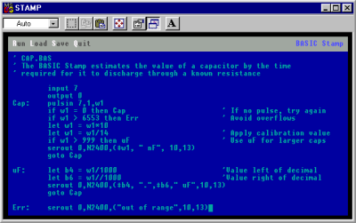
For an IDE, the Basic Stamp editor is comparable to earlier Arduino IDEs; Alt+R runs the program on the Stamp connected to the computer, Alt+L loads a program, Alt+S saves a program, and Alt+Q quits the editor.

The BASIC language implemented on the PIC is minimal, but it does everything you would expect; individual pins can be set as input and output, buttons are debounced, and PWM functions are baked into the language.

An ad for the Basic Stamp. From High Tech Entrepreneur, October/November 1993. Ads had text in the past.

Context

The Basic Stamp is now regarded as a slow, inconvenient artifact from the past. No one uses it, and the only place you’ll find one is in the back cabinet in a physics or EE classroom. This is an incredible disservice to a still-impressive piece of technology, and looking back at the Basic Stamp with our modern expectations is an incredible bias.

There were microcontroller development platforms before the Basic Stamp, but these were engineering tools, and expensive compared to the Stamp. Development platforms for the electrical hobbyist were around after the stamp, too: the Micromint Domino packed an entire development platform into a rectangular brick of plastic. None of these designs could match the popularity of the Basic Stamp despite the platform’s shortcomings.

The Arduino receives a lot of hate. Detractors say it’s too high-level for proper embedded programming, not high-level enough for a modern workflow, is based on old, obsolete chips, doesn’t have the features of modern ARM microcontrollers, and the IDE is a mess. Despite an even less capable IDE, meager memory, and a slow processor, the Basic Stamp proved incredibly popular. The fact that you could pick up a Basic Stamp development kit at any Radio Shack probably didn’t hurt it’s popularity, either.

Now, with our fancy IDEs, mbed microcontrollers, powerful ARMs, and huge libraries, the ease of use of the Basic Stamp has still not been equaled. It may be slow, outdated, but all of us owe a great debt to the Basic Stamp for introducing an entire generation to the world of embedded programming, microcontrollers, and electronics tinkering.


Filed under: classic hacks, Featured, Microcontrollers

Hackaday Prize Entry: PICs and Arduinos, Cats and Dogs Living Together

Half of our little corner of the Internet complains about the Arduino, how the pin headers of the Arduino standard don’t make any sense, how the Arduino IDE is rubbish, gives well-reasoned arguments why the Arduino language is hindering the next generation of embedded programmers, and laments the fact that everything is commoditized into Arduino-compatible packages. The other half of our little corner of the Internet uses Microchip PICs.

[Jarrett] is stubborn, and he wants to use a PIC with the distinctive Arduino pin layout. Thus was born PIC-On-The-Go. It’s a PIC18F4520 in the familiar goofy-pin package, made specifically for everyone who just wants to buckle down and get some work done.

This isn’t the only PIC-become-Arduino board out there; the Fubarino is a great board that speaks Arduino, but that doesn’t take advantage of our favorite Arduino shields. Either way, we’re surprised something like [Jarrett]’s project doesn’t exist yet, making it a great entry for The Hackaday Prize.

The 2015 Hackaday Prize is sponsored by:


Filed under: The Hackaday Prize

3d printed hexapod robot

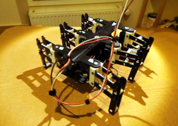
This hexapod was made almost entirely via 3d printing (translated). The parts that you need to supply include a few fasteners to make connections, twelve servo motors, and a method of driving them. As you can see in the video after the break, all those parts come together into a little robot that functions quite well. The only thing that we think is missing are some grippy feet to help prevent slipping.

[Hugo] calls the project Bleuette. It is completely open source, with the cad files and source code available on his Github repository. There is additional information in the wiki page of that repo. This gives us a good look at the electronic design. He’s controlling the legs with an Arduino, but it’s all dependent on his own shield which features a PIC 18F452 to take care of the signals used to drive all of the servo motors. The board also has some peripherals to monitor the current draw and regulate the incoming power.


Filed under: robots hacks
Hack a Day 30 Jan 20:01

The PICnDuino Review

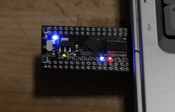
For those of you that can’t make a decision between buying an Arduino and a PIC processor, [Brad] has come up with a novel solution, the PICnDuino. We’ve featured him before with his [Retroball] project, but this time Brad has been full funded on Kickstarter, and is pre-selling boards for delivery in March.

[HAD], specifically I, was fortunate enough to be sent one of the boards to try out early. I’ve worked with an Arduino before, but never a PIC processor, so read on to see if it was actually as easy as the tutorial video (at the end of the article) would have you believe it is to get started.

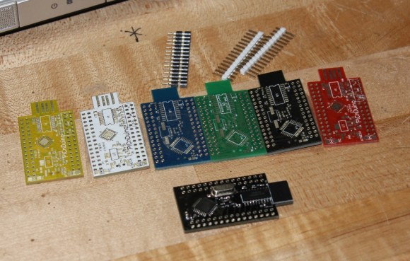
I was sent both a black board fully populated, as well as several blanks in the various colors pictured below.  After loosely attaching the headers, I found that the oscillator on the bottom makes the board sit up a bit when placed into a breadboard. This is actually a clever design feature to make sit up a bit to allow USB attachment while breadboarded. After a quick physical inspection, the real trick would be seeing if it worked as advertised.

The first challenge for me was that, according to the documentation, this board runs in Windows or a virtualisation environment. I normally run Ubuntu, so, grabbing my wife’s circa 2000 vintage XP notebook, I downloaded and Amicus and Arduino software as explained in the video tutorial. The tutorial really spells out how to get the software running. This would be great for a total beginner, and made it so I didn’t have to even poke around for where to get the software.

The only issue I had connecting to the board(s?)was that I had to manually install the Amicus18 USB driver. I’m a total noob when it comes to the PIC processor, and only have limited experience with the Arduino, but once the driver was updated, it was quite easy to get everything going.

After programming a “blink” sketch using it as an Arduino, I then flipped a switch and opened the Amicus IDE. Programming the PIC was also simple, although I had to use a and modify a program called “LED_Flash” to match the video instead of the “blink” program as described in the tutorial. It was a bit strange to see the built in blinking light for the Arduino still working while the PIC was being programmed, as well as both built-in lights blinking slightly offset while running simultaneously.

The documentation is extremely well done for a product that won’t even be available for delivery until March 2013. I’m really excited to play with it more, and I think it will be a great tool for people to either run two processors simultaneously, or just have the option of learning to program both a PIC and (n) Arduino. So check it out here, and get it shipped worldwide straight out of Australia!

Side note, bonus points if you can tell from the two pictures what kind of computer I used for this review!


Filed under: arduino hacks, reviews

Review: Gooligum Electronics PIC Training Course and Development Board

Introduction

[Updated 18/06/2013]

There are many types of microcontrollers on the market, and it would be fair to say one of the two most popular types is the Microchip PIC series. The PICs are great as there is a huge range of microcontrollers available across a broad range of prices. However learning how to get started with the PIC platform isn’t exactly simple. Not that we expect it to be, however a soft start is always better. There are some older books, however they can cost more than $100 – and are generally outdated. So where do you start?

It is with this problem in mind that led fellow Australian David Meiklejohn to develop and offer his PIC Training Course and Development Board to the marketplace via his company Gooligum Electronics.

In his words:

There is plenty of material available on PICs, which can make it daunting to get started.  And some of the available material is dated, originally developed before modern “flash” PICs were available, or based on older devices that are no longer the best choice for new designs.  Our approach is to introduce PIC programming and design in easy stages, based on a solid grounding in theory, creating a set of building blocks and techniques and giving you the confidence to draw on as we move up to more complex designs.

So in this article we’ll examine David’s course package. First of all, let’s look at the development board and inclusions. Almost everything you will need to complete all the lessons is included in the package, including the following PIC microcontrollers:

You can choose to purchase the board in kit form or pre-assembled. If you enjoy soldering, save the money and get the kit – it’s simple to assemble and a nice way to spend a few hours with a soldering iron.

Although the board includes all the electronic components and PICs – you will need are a computer capable of running Microchip MPLAB software, a Microchip PICkit3 (or -2) programming device and an IC extractor. If you’re building the kit, a typical soldering iron and so on will be required. Being the  ultra-paranoid type, I bought a couple extra of each PIC to have as spares, however none were damaged in my experimenting. Just use common-sense when handling the PICs and you will be fine.

Assembly

Putting the kit board together wasn’t difficult at all. There isn’t any surface-mount parts to worry about, and the PCB is silk-screened very well:

The rest of the parts are shipped in antistatic bags, appropriately labelled and protected:

Assembly was straight forward, just start with the low-profile parts and work your way up. The assembly guide is useful to help with component placement. After working at a normal pace, it was ready in just over an hour:

The Hardware

Once assembled (or you’ve opened the packaging) the various sections of the board are obvious and clearly labelled – as they should be for an educational board. You will notice a large amount of jumper headers – they are required to bridge in and out various LEDs, select various input methods and so on. A large amount of jumper shunts is included with the board.

It might appear a little disconcerting at first, but all is revealed and explained as you progress through the lessons. The board has decent rubber feet, and is powered either by the PICkit3 programmer, or a regulated DC power source between 5 and 6V DC, such as from a plug-pack if you want to operate your board away from a PC.

However there is a wide range of functions, input and output devices on the board – and an adjustable oscillator, as shown in the following diagram:

The Lessons

There is some assumed knowledge, which is a reasonable understanding of basic electronics, some computer and mathematical savvy and the C programming language.

You can view the first group of lessons for free on the kit website, and these are included along with the additional lessons in the included CDROM. They’re in .pdf format and easy to read. The CDROM also includes all the code so you don’t have to transcribe it from the lessons. Students start with an absolute introduction to the system, and first learn how to program in assembly language in the first group of tutorials, followed by C in the second set.

This is great as you learn about the microcontroller itself, and basically start from the bottom. Although it’s no secret I enjoy using the Arduino system – it really does hide a lot of the actual hardware knowledge away from the end user which won’t be learned. With David’s system – you will learn.

If you scroll down to the bottom of this page, you can review the tutorial summaries. Finally here’s a quick demonstration of the 7-segment displays in action:

Update – 18/06/2013

David has continued publishing more tutorials for his customers every few months – including such topics as the EEPROM and pulse-width modulation. As part of the expanded lessons you can also get a pack which allows experimenting with electric motors that includes a small DC motor, the TI SN75441 h-bridge IC, N-channel and P-channel MOSFETS and more:

So after the initial purchase, you won’t be left on your own. Kudos to David for continuing to support and develop more material for his customers.

Where to from here? 

Once you run through all the tutorials, and feel confident with your knowledge, the world of Microchip PIC will be open to you. Plus you now have a great development board for prototyping with 6 to 14-pin PIC microcontrollers. Don’t forget all the pins are brought out to the row of sockets next to the solderless breadboard, so general prototyping is a breeze.

Conclusion

For those who have mastered basic electronics, and have some C or C-like programming experience from using other development environments or PCs – this package is perfect for getting started with the Microchip PIC environment. Plus you’ll learn about assembly language – which is a good thing. I genuinely recommend this to anyone who wants to learn about PIC and/or move into more advanced microcontroller work. And as the entire package is cheaper than some books –  you can’t go wrong. The training course is available directly from the Gooligum website.

Disclaimer – The Baseline and Mid-Range PIC Training Course and Development Board was a promotional consideration from Gooligum Electronics.

In the meanwhile have fun and keep checking into tronixstuff.com. Why not follow things on twitterGoogle+, subscribe  for email updates or RSS using the links on the right-hand column? And join our friendly Google Group – dedicated to the projects and related items on this website. Sign up – it’s free, helpful to each other –  and we can all learn something.

The post Review: Gooligum Electronics PIC Training Course and Development Board appeared first on tronixstuff.

Raspberry Pi teases finished Gertboard I/O extender, revs creative engines

The Raspberry Pi faithful have been looking forward to the Gertboard almost as much as the main device itself: Gert van Loo's I/O extender promises to flash lights, spin motors and otherwise take on the tasks that the Raspberry Pi doesn't directly manage on its own. While we've seen work on the project since late 2011, the expansion now looks to be closer to reality following a fresh teaser. The refined design's biggest tweak is replacing its original PIC controller with an Arduino-powered chip -- an element no doubt familiar to the crowd that would already be looking at a very hackable, miniature Linux computer. Most everything else is a refinement, although Gert has brought in three physical buttons and two-channel analog-to-digital and digital-to-analog converters. We'll learn the full story later this week, and until then we'll be dreaming of all the off-kilter Arduino projects that might be made better with a little Raspberry Pi companionship.

Filed under: Misc. Gadgets, Peripherals

Raspberry Pi teases finished Gertboard I/O extender, revs creative engines originally appeared on Engadget on Wed, 08 Aug 2012 18:41:00 EST. Please see our terms for use of feeds.

Permalink | Email this | Comments