Posts with «microchip» label

Learn Microchip AVR Programming with “AVR Workshop A Hands-On Introduction with 60 Projects”

After many years working with and teaching others about the Arduino development platform, it became apparent that there needed to be a useful guide to get people started in the world of AVR microcontrollers – used in Arduino and other development environments. The great people at No Starch Press agreed and we are now proud to have published “AVR Workshop – A Hands-On Introduction with 60 Projects“.

AVR Workshop is written for several groups of people:

  • Those of you who have used an Arduino but now want to learn how to harness the underlying AVR microcontrollers without the layer of Arduino abstraction.
  • Anyone interested in electronics and wanting to start with using microcontrollers.
  • Students who are going to learn how to use AVR microcontrollers in their coursework.
  • People tasked with making devices based around 8-bit AVR microcontrollers and don’t know where to start
  • AVR users who would like a neat reference on using popular devices with their microcontrollers and don’t have all day to scour the Internet for tested, quality resources.
  • You. Yes, you. Learning is for a lifetime, so why not get started with the world of electronics and microcontrollers? Or give a copy to someone who enjoys learning about technology?

Anyone can use this book. You don’t need any previous experience in electronics, programming, or making things. AVR Workshop will take you step-by-step from the beginning including installation of the required software, explain electronics when required, teach you the required coding and walk you through examples including sixty projects enabling you to harness popular 8-bit Microchip AVR microcontrollers.

Once you’ve worked through the book – you will have the knowledge, experience and confidence to branch out on your own and build complex projects, work with other Microchip AVR microcontrollers – and find success in this fascinating field. You will also have a useful reference tool that you can refer to when making your own devices.

Unlike other books or resources found online, I don’t hide any details from you in order to simplify things. Important functions aren’t hidden away in software libraries – instead you’ll learn how to control the microcontroller down to the register level to control all sorts of useful devices. Instead of relying on others – you’ll learn how to write your own libraries, so you can make your own parts and devices easier to work with.

You don’t need to spend a fortune, in fact I’ve written AVR Workshop to be as economical as possible for you, the reader. The required software is small, free to download and can operate on Linux, MacOS or Windows using machines that date back almost ten years. You don’t need any cloud-based tools or the latest i7 or M2-based computer… almost any will do.

AVR Workshop is printed using a convenient lie-flat technology, so you can have the book open to your side and not worry about the pages flapping about and losing your position while working on your projects. All the required code is included in the book, however you can also download them along with a list of parts and supplier information from the book’s website.

The Microchip AVR series of 8-bit microcontrollers are, in my opinion, an inexpensive and most approachable way of learning about electronics and microcontrollers – and open up a whole new world of creativity or even the pathway to a career in technology. A copy of AVR Workshop is the best guide to start anyone in this world.

To learn more about AVR Workshop, you can review the table of contents, download a sample chapter, code and parts list and order copies for yourself and others from the No Starch Press online store. Orders from No Starch Press also include a free electronic copy so you can get started immediately.

You can also purchase copies from amazonkindle, or your preferred bookseller. Readers in Australia can order directly from the Tronixlabs store.

And whatever you do, have fun and make something!

Tronixstuff 17 Oct 01:48
avr  microchip  

Arduino with a… PIC?

Before the Arduino took over the hobby market (well, at least the 8-bit segment of it), most hackers used PIC processors. They were cheap, easy to program, had a good toolchain, and were at the heart of the Basic Stamp, which was the gateway drug for many microcontroller developers.

[AXR AMR] has been working with the Pinguino, an Arduino processor based on a PIC (granted, an 18F PIC, although you can also use a 32-bit device, too). He shows you how to build a compatible circuit on a breadboard with about a dozen parts. The PIC has built-in USB. Once you flash the right bootloader, you don’t need anything other than a USB cable to program. You can see a video of this below.

You will need a programmer to get the initial bootloader, but there’s plenty of cheap options for that. The IDE is available for Windows, Linux, and the Mac. Of course, you might wonder why you would use a PIC device instead of the more traditional Arduino devices. The answer is: it depends. Every chip has its own set of plusses and minuses from power consumption to I/O devices, to availability and price. These chips might suit you, and they might not. That’s your call.  Of course, the difference between Microchip and Atmel has gotten less lately, too.

We’ve covered Pinguino before with a dedicated board. If you never played with a Basic Stamp, you might enjoy learning more about it. If you’re looking for more power than a PIC 18F can handle, you might consider the Fubarino, a PIC32 board you can use with the Arduino IDE.


Filed under: Arduino Hacks, Microcontrollers

Review: Gooligum Electronics PIC Training Course and Development Board

Introduction

[Updated 18/06/2013]

There are many types of microcontrollers on the market, and it would be fair to say one of the two most popular types is the Microchip PIC series. The PICs are great as there is a huge range of microcontrollers available across a broad range of prices. However learning how to get started with the PIC platform isn’t exactly simple. Not that we expect it to be, however a soft start is always better. There are some older books, however they can cost more than $100 – and are generally outdated. So where do you start?

It is with this problem in mind that led fellow Australian David Meiklejohn to develop and offer his PIC Training Course and Development Board to the marketplace via his company Gooligum Electronics.

In his words:

There is plenty of material available on PICs, which can make it daunting to get started.  And some of the available material is dated, originally developed before modern “flash” PICs were available, or based on older devices that are no longer the best choice for new designs.  Our approach is to introduce PIC programming and design in easy stages, based on a solid grounding in theory, creating a set of building blocks and techniques and giving you the confidence to draw on as we move up to more complex designs.

So in this article we’ll examine David’s course package. First of all, let’s look at the development board and inclusions. Almost everything you will need to complete all the lessons is included in the package, including the following PIC microcontrollers:

You can choose to purchase the board in kit form or pre-assembled. If you enjoy soldering, save the money and get the kit – it’s simple to assemble and a nice way to spend a few hours with a soldering iron.

Although the board includes all the electronic components and PICs – you will need are a computer capable of running Microchip MPLAB software, a Microchip PICkit3 (or -2) programming device and an IC extractor. If you’re building the kit, a typical soldering iron and so on will be required. Being the  ultra-paranoid type, I bought a couple extra of each PIC to have as spares, however none were damaged in my experimenting. Just use common-sense when handling the PICs and you will be fine.

Assembly

Putting the kit board together wasn’t difficult at all. There isn’t any surface-mount parts to worry about, and the PCB is silk-screened very well:

The rest of the parts are shipped in antistatic bags, appropriately labelled and protected:

Assembly was straight forward, just start with the low-profile parts and work your way up. The assembly guide is useful to help with component placement. After working at a normal pace, it was ready in just over an hour:

The Hardware

Once assembled (or you’ve opened the packaging) the various sections of the board are obvious and clearly labelled – as they should be for an educational board. You will notice a large amount of jumper headers – they are required to bridge in and out various LEDs, select various input methods and so on. A large amount of jumper shunts is included with the board.

It might appear a little disconcerting at first, but all is revealed and explained as you progress through the lessons. The board has decent rubber feet, and is powered either by the PICkit3 programmer, or a regulated DC power source between 5 and 6V DC, such as from a plug-pack if you want to operate your board away from a PC.

However there is a wide range of functions, input and output devices on the board – and an adjustable oscillator, as shown in the following diagram:

The Lessons

There is some assumed knowledge, which is a reasonable understanding of basic electronics, some computer and mathematical savvy and the C programming language.

You can view the first group of lessons for free on the kit website, and these are included along with the additional lessons in the included CDROM. They’re in .pdf format and easy to read. The CDROM also includes all the code so you don’t have to transcribe it from the lessons. Students start with an absolute introduction to the system, and first learn how to program in assembly language in the first group of tutorials, followed by C in the second set.

This is great as you learn about the microcontroller itself, and basically start from the bottom. Although it’s no secret I enjoy using the Arduino system – it really does hide a lot of the actual hardware knowledge away from the end user which won’t be learned. With David’s system – you will learn.

If you scroll down to the bottom of this page, you can review the tutorial summaries. Finally here’s a quick demonstration of the 7-segment displays in action:

Update – 18/06/2013

David has continued publishing more tutorials for his customers every few months – including such topics as the EEPROM and pulse-width modulation. As part of the expanded lessons you can also get a pack which allows experimenting with electric motors that includes a small DC motor, the TI SN75441 h-bridge IC, N-channel and P-channel MOSFETS and more:

So after the initial purchase, you won’t be left on your own. Kudos to David for continuing to support and develop more material for his customers.

Where to from here? 

Once you run through all the tutorials, and feel confident with your knowledge, the world of Microchip PIC will be open to you. Plus you now have a great development board for prototyping with 6 to 14-pin PIC microcontrollers. Don’t forget all the pins are brought out to the row of sockets next to the solderless breadboard, so general prototyping is a breeze.

Conclusion

For those who have mastered basic electronics, and have some C or C-like programming experience from using other development environments or PCs – this package is perfect for getting started with the Microchip PIC environment. Plus you’ll learn about assembly language – which is a good thing. I genuinely recommend this to anyone who wants to learn about PIC and/or move into more advanced microcontroller work. And as the entire package is cheaper than some books –  you can’t go wrong. The training course is available directly from the Gooligum website.

Disclaimer – The Baseline and Mid-Range PIC Training Course and Development Board was a promotional consideration from Gooligum Electronics.

In the meanwhile have fun and keep checking into tronixstuff.com. Why not follow things on twitterGoogle+, subscribe  for email updates or RSS using the links on the right-hand column? And join our friendly Google Group – dedicated to the projects and related items on this website. Sign up – it’s free, helpful to each other –  and we can all learn something.

The post Review: Gooligum Electronics PIC Training Course and Development Board appeared first on tronixstuff.

Low cost Ethernet shield with ENC28J60

Economical alternative to original Arduino ethernet shields, allows data rates up to 10 Mbps and is achieved with a traditional assembly components.

One of the most interesting shield that you can mount on the Arduino platform is certainly the ethernet shield, because enable numerous networking applications such as remote control of systems and users, web access and publication of data, and more yet, the simplicity of finding and integrating open-source libraries on Arduino IDE does the rest. The usefulness of LAN connectivity has meant that the market would respond by offering different ethernet shield, first of all the original Arduino Ethernet Shield, which was accompanied by the good shield by Seeed Studio, both of these circuits are based on the chipset WIZnet W5100, allow multiple socket connections and can work at 100 Mbps

This ethernet shield is low-cost thanks to components used: all traditional mounting (THT). This feature makes the circuit accessible to those who haven’t the equipment to assemble SMD components. The data-rate is limited to 10 Mbps.


Wiring diagram

The shield is based on a Microchip ENC28J60 chip that interfaces with Arduino and data conversion according to the ethernet protocol. It integrates the MAC controller, an 8 KB Transmit / Receive Packet Dual Port Buffer and a circular FIFO managed at the hardware level, allows the programming of data retransmission in case of collision.
The MAC controller supports both Unicast, Multicast and Broadcast packets, has a programmable 64-byte pattern within a margin allowed to the user and programmable wake-up on multiple packet formats (Magic Packet, Unicast, Multicast, Broadcast, specific packet match or any packet).


In the circuit we see that over all’ENC28J60 there are a standard RJ45 jack with integrated LEDs, filters and line transformers, and a voltage level shifter for the SPI interface to communicate with the Arduino.

MISO is the output data of the slave device and the input of Arduino, while MOSI is the opposite; SCK is the clock that marks the two-way communication on the SPI bus and RESET the reset line, which is also connected to a button that allows you to reset the Ethernet interface, if necessary, manually. The digital D10 and D2 lines of Arduino are used, respectively, for the control of CS (Chip Select, active logic zero) and the reading of INT. U3B is used to adapt the logic levels 0/3, 3 V to those of Arduino 0/5 V.

The ENC28J60 operates with a clock of 25 MHz, defined by the quartz Q1 connected between the pins 23 and 24; the capacitor connected to pin VCAP filters the output voltage (2.5 V) of the internal controller and should preferably be of the type low ESR (low series resistance parasite). The resistor connected to RBIAS is used to bias the LAN transceiver that is part of the pin TPIN + / – and TPOUT + / -.

We conclude the analysis of the circuit diagram of the shield with the power that is drawn by Arduino 5V and Vin through the strip: the first provides the 5 volts continuous stabilized points of the circuit that require them (basically the 74HC125 and the resistance of pull Line-up reset and Chip Select) and the second give power to the integrated regulator U2, which creates the 3.3 volts needed to power the microcontroller and circuits contained in the RJ45 jack.


The library for ENC28J60


The original library from which we derived can be downloaded from the site https://github.com/jcw/ethercard ; from our site you can download the library itself but with a higher number of application examples.

Here you will find a sketch example to build a Web Server, in particular, in the current web page you will see the hours: minutes: seconds elapsed from the ignition of Arduino.


// This is a demo of the RBBB running as webserver 
// with the Ether Card
// 2010-05-28 
// http://opensource.org/licenses/mit-license.php

#include

// ethernet interface mac address
static byte mymac[] = { 0x74,0x69,0x69,0x2D,0x30,0x31 };
// ethernet interface ip address
static byte myip[] = { 192,168,0,188 };
// gateway ip address
static byte gwip[] = { 192,168,0,1 };

byte Ethernet::buffer[500];
BufferFiller bfill;

void setup () {
  if (ether.begin(sizeof Ethernet::buffer, mymac) == 0)
    Serial.println( "Failed to access Ethernet controller");
  ether.staticSetup(myip);
}

static word homePage() {
  long t = millis() / 1000;
  word h = t / 3600;
  byte m = (t / 60) % 60;
  byte s = t % 60;
  bfill = ether.tcpOffset();
  bfill.emit_p(PSTR(
    "HTTP/1.0 200 OK\r\n"
    "Content-Type: text/html\r\n"
    "Pragma: no-cache\r\n"
    "\r\n"
    "<meta http-equiv='refresh' content='1'/>"
    "<title>RBBB server</title>" 
    "<h1>$D$D:$D$D:$D$D</h1>"),
      h/10, h%10, m/10, m%10, s/10, s%10);
  return bfill.position();
}

void loop () {
  word len = ether.packetReceive();
  word pos = ether.packetLoop(len);

  if (pos)  // check if valid tcp data is received
    ether.httpServerReply(homePage()); // send web page data
}


Library Ethernet shild with ENC28J60 

Store

Arduino WiFi Shield


The shield most used in practice are those that expand the communication of the Arduino board and in particular those that allow to add a network connection to a TCP / IP.
The first shield of this kind were those based on Ethernet technology, which helps the Arduino to connect to a LAN based on Ethernet TCP / IP, and so to Internet.
The convenience of Wi-Fi is now known to all: no more cables to spread (which increases the cost and time of construction of any plant) and full freedom in the positioning of the different nodes of the wireless network.

One of the first companies to focus on Wi-Fi was the AsyncLabs, who proposed a famous WiFi shield, including the appropriate libraries.
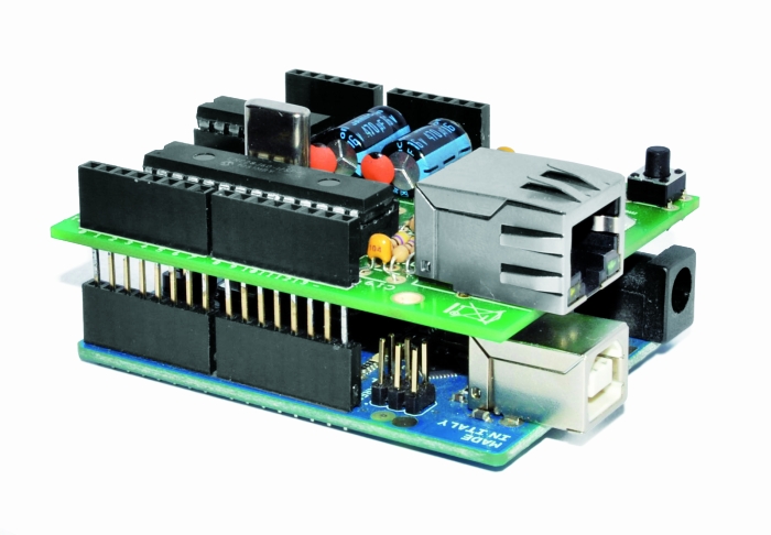
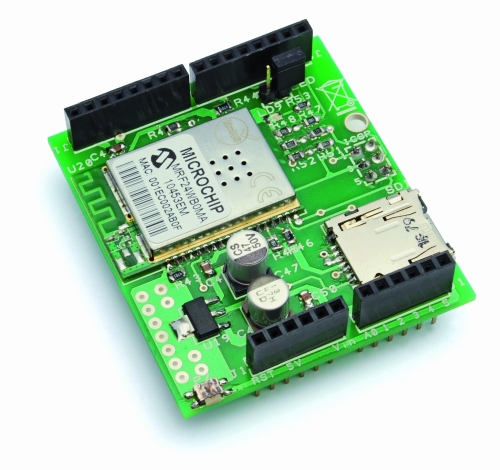
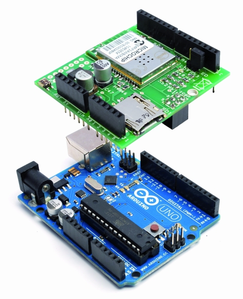
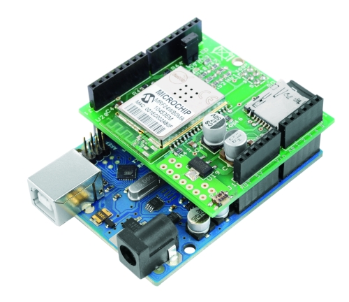
What we propose is a new solution for Wi-Fi: this is a shield that the hardware was inspired by that of AsyncLabs, but in addition, we have provided a slot for microSD memory.

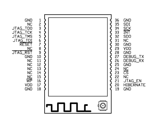
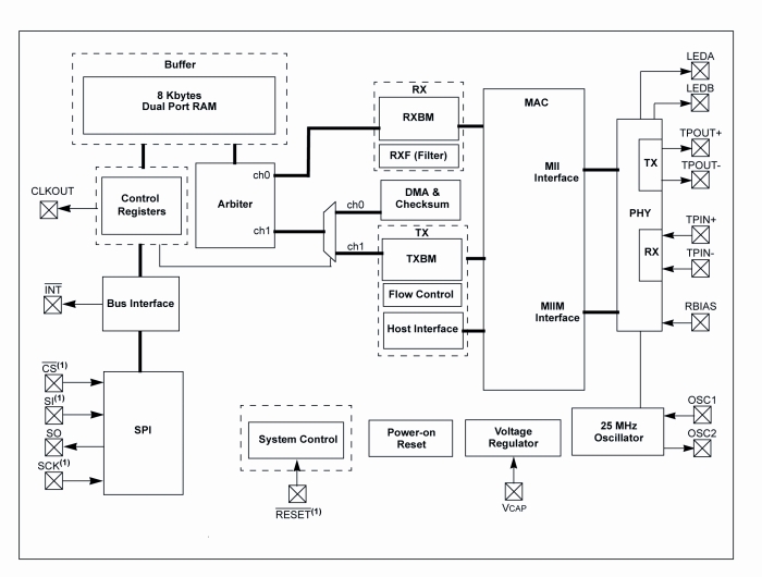
The basic component of the shield that we have made is a Wi-Fi module MRF24WB0MA manufactured by Microchip.
The device is a Wi-Fi IEEE 802.11 RF transceiver, with a data rate between 1 and 2 Mbps, and with an internal antenna.
The WiFi shield supports both types of wireless networks infrastructure (BSS) and ad-hoc (IBSS) and is also allowed to connect to secure networks (cryptographers and are supported 64 and 128-bit WEP, WPA/WPA2 and TKIP, AES and PSK).

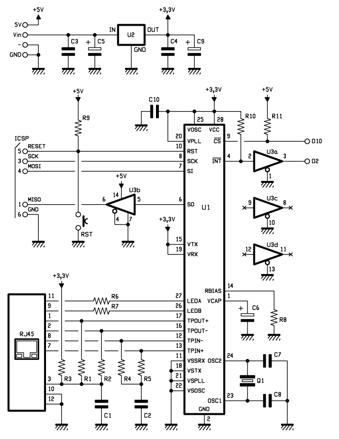
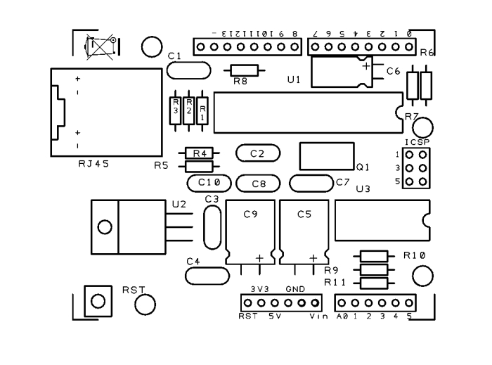
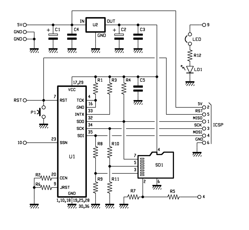
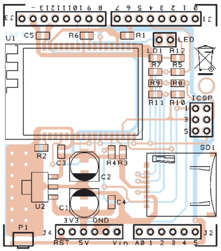
In our project is using the SPI connection for communication with the WiFi controller through the SDO, SCK and SDI (pin 32, 34 and 35) and, if necessary, can be reset using a button (P1 in the diagram).
Peculiarities of our shield is that it has a SD card slot (SD1 signed in the schematic), managed by Arduino always through the SPI port.
There is also a LED (LD1 signed) used to indicate whether the Wi-Fi is active or not, its management is implemented through a hardware port, so you usually can not be used by software. In the event that was needed precisely this port, you still have a jumper that, when opened, making it available again disconnect the LED pin I / O.
Finally, to complete the hardware of the shield there is a section dedicated to the power, consists of a 3.3 V voltage regulator (indicated with U2).

BOM

R1: 4,7 kohm (0805)
R2: 4,7 kohm (0805)
R3: 4,7 kohm (0805)
R4: 4,7 kohm (0805)
R5: 1 kohm (0805)
R6: 4,7 kohm (0805)
R7: 2,2 kohm (0805)
R8: 1 kohm (0805)
R9: 2,2 kohm (0805)
R10: 1 kohm (0805)
R11: 2,2 kohm (0805)
R12: 330 ohm (0805)

C1: 220 µF 6,3 VL (D)
C2: 220 µF 6,3 VL (D)
C3: 100 nF (0805)
C4: 100 nF (0805)
C5: 100 nF (0805)

LD1: Led (0805)

U1: MRF24WB0MA/RM
U2: TC1262-3.3 (SOT-223)

SD1: µSD-Card (MICROSDSOCK2)

P1: switch SMD

Varie:
- headers  male 2 via
- headers  M/F 6 via(2 pz.)
- headers  M/F 8 via(2 pz.)
- headers  M/F 3 via(2 pz.)
- Jumper
- PCB

The library supports various operating modes, which are Web Server, Web Client, Socket, UDP and WiServer.

The library is constantly evolving, so we have provided a space where they will be published on code.google.com various versions available.

Code Example for WiFi shield

 Web Client

/******************************************************
 SoftwareDemo2WebClientWiFi
 Esempio codice Web Client tramite Wi-Fi
 Autori: Ingg. Tommaso Giusto e Ing. Alessandro Giusto
 Email:  tommro@libero.it
******************************************************/

// Inclusione Libreria per Server Web WiFi
#include <WiServer.h>

// Definizione Parametri Rete Wireless
#define WIRELESS_MODE_INFRA	1  // Infrastrutturata (basata su Access Point)
#define WIRELESS_MODE_ADHOC	2  // Ad-hoc (senza Access Point)

unsigned char local_ip[] = {192, 168, 1, 250};      // Indirizzo IP
unsigned char gateway_ip[] = {192, 168, 1, 91};	    // Indirizzo gateway IP
unsigned char subnet_mask[] = {255, 255, 255, 0};   // Subnet Mask
const prog_char ssid[] PROGMEM = {"Sitecom"};	    // SSID access point

// Selezione tipo di cifratura rete Wireless
unsigned char security_type = 0;  // 0 -> nessuna cifratura
                                  // 1 -> cifratura WEP
                                  // 2 -> cifratura WPA
                                  // 3 -> cifratura WPA2

// Password cifratura per WPA/WPA2 (max. 64 cratteri)
const prog_char security_passphrase[] PROGMEM = {"12345678"};

// Password cifratura per WEP 128-bit keys
prog_uchar wep_keys[] PROGMEM = {0x01, 0x02, 0x03, 0x04, 0x05, 0x06, 0x07, 0x08, 0x09, 0x0a, 0x0b, 0x0c, 0x0d,
				 0x00, 0x00, 0x00, 0x00, 0x00, 0x00, 0x00, 0x00, 0x00, 0x00, 0x00, 0x00, 0x00,
				 0x00, 0x00, 0x00, 0x00, 0x00, 0x00, 0x00, 0x00, 0x00, 0x00, 0x00, 0x00, 0x00,
				 0x00, 0x00, 0x00, 0x00, 0x00, 0x00, 0x00, 0x00, 0x00, 0x00, 0x00, 0x00, 0x00};

// Selezione tipo di rete Wireless infrastrutturata
unsigned char wireless_mode = WIRELESS_MODE_INFRA;

// Variabili per lunghezza SSID e password di cifratura
unsigned char ssid_len;
unsigned char security_passphrase_len;

// Definizione Parametri Google Search
// Indirizzo IP per server www.google.it
uint8 google_ip[] = {209, 85, 148, 106};

// Richiesta GET verso GOOGLE
GETrequest getGoogleSearch (google_ip, 80, "www.google.it", "/search?q=ElettronicaIn");

// Inizializzazione Scheda
void setup() {
  // Inizializzo WiServer (NULL indica non dobbiamo servire pagine Web)
  WiServer.init (NULL);
  // Inizializzo porta seriale
  Serial.begin (9600);
  WiServer.enableVerboseMode (false);

  // Inizializzazione richiesta GET (parametro indica funzione a cui verra' passata la risposta)
  getGoogleSearch.setReturnFunc (Gestione_Risposte_Web);
}

// Variabile memorizzazione riavvio (millisecondi) di esecuzione ricerca
long updateSearch = 0;

// Programma Principale
void loop() {
  // Se passato periodo di attesa esecuzione ricerca
  if (millis() >= updateSearch) {
    // Eseguo ricerca
    getGoogleSearch.submit();
    // Aggiorno tempo di riavvio (attensa di 1 ora)
    updateSearch = updateSearch + (1000 * 60 * 60);
  }

  // Avvio WiServer
  WiServer.server_task();

  // Attesa
  delay(10);
}

// Gestione diverse risposte provenienti dal WEB
void Gestione_Risposte_Web (char* data, int len) {
  // Stampo la risposta proveniente dal WEB su porta seriale
  int i;

  // Stampo i singoli caratteri della risposta proveniente dal WEB su porta seriale
  for (i = 0; i < len; i++) {
    Serial.print(*(data));
    data++;
  }
}

Web Server

/******************************************************
 SoftwareDemo1WebServerWiFi
 Esempio codice Web Server tramite Wi-Fi
 Autori: Ingg. Tommaso Giusto e Ing. Alessandro Giusto
 Email:  tommro@libero.it
******************************************************/

// Inclusione Libreria per Server Web WiFi
#include <WiServer.h>

// Definizione pin INPUT/OUTPUT
int Pin_Led_Rosso = 7;  // Led rosso uscita digitale 7

// Definizione Variabili Globali Stato Led
byte Stato_Led_Rosso = 0;  // Stato led rosso

// Definizione Parametri Rete Wireless
#define WIRELESS_MODE_INFRA	1  // Infrastrutturata (basata su Access Point)
#define WIRELESS_MODE_ADHOC	2  // Ad-hoc (senza Access Point)

unsigned char local_ip[] = {192, 168, 1, 250};      // Indirizzo IP
unsigned char gateway_ip[] = {192, 168, 1, 91};	    // Indirizzo gateway IP
unsigned char subnet_mask[] = {255, 255, 255, 0};   // Subnet Mask
const prog_char ssid[] PROGMEM = {"Sitecom"};	    // SSID access point

// Selezione tipo di cifratura rete Wireless
unsigned char security_type = 0;  // 0 -> nessuna cifratura
                                  // 1 -> cifratura WEP
                                  // 2 -> cifratura WPA
                                  // 3 -> cifratura WPA2

// Password cifratura per WPA/WPA2 (max. 64 cratteri)
const prog_char security_passphrase[] PROGMEM = {"12345678"};

// Password cifratura per WEP 128-bit keys
prog_uchar wep_keys[] PROGMEM = {0x01, 0x02, 0x03, 0x04, 0x05, 0x06, 0x07, 0x08, 0x09, 0x0a, 0x0b, 0x0c, 0x0d,
				 0x00, 0x00, 0x00, 0x00, 0x00, 0x00, 0x00, 0x00, 0x00, 0x00, 0x00, 0x00, 0x00,
				 0x00, 0x00, 0x00, 0x00, 0x00, 0x00, 0x00, 0x00, 0x00, 0x00, 0x00, 0x00, 0x00,
				 0x00, 0x00, 0x00, 0x00, 0x00, 0x00, 0x00, 0x00, 0x00, 0x00, 0x00, 0x00, 0x00};

// Selezione tipo di rete Wireless infrastrutturata
unsigned char wireless_mode = WIRELESS_MODE_INFRA;

// Variabili per lunghezza SSID e password di cifratura
unsigned char ssid_len;
unsigned char security_passphrase_len;

// Inizializzazione Scheda
void setup() {
  // Inizializzo pin usati come INPUT/OUTPUT
  pinMode (Pin_Led_Rosso, OUTPUT);

  // Inizializzo WiServer (Gestione_Richieste_Web per creare/trasmettere pagine HTML)
  WiServer.init (Gestione_Richieste_Web);
  // Inizializzo porta seriale
  Serial.begin (9600);
  WiServer.enableVerboseMode (false);

  // Spengo led rosso
  Led_Rosso_OFF();
}

// Programma Principale
void loop() {
  // Avvio WiServer
  WiServer.server_task();
}

// Gestione diverse richieste provenienti dal WEB
// INPUT:   URL pagina web richiesta
// OUTPUT:  Flag URL riconosciuto/non riconosciutoo
boolean Gestione_Richieste_Web (char* URL) {
  // Se URL richieso corrisponde a "/" (pagina index)
  if (strcmp (URL, "/") == 0) {
    // Secondo gli I/O creo e invio le pagine Web
    Invia_Pagina_Web();

    // Ritorno URL è stato riconosciuto
    return (true);
  }    // Chiusura if URL richieso corrisponde a "/" (pagina index)

  // Se URL richieso corrisponde a "?OPERATION=ACCENDI_ROSSO
  if (strcmp (URL, "/?OPERATION=ACCENDI_ROSSO") == 0) {
    // Accendo led rosso
    Led_Rosso_ON();
    Stato_Led_Rosso = 1;

    // Secondo gli I/O creo e invio le pagine Web
    Invia_Pagina_Web();

    // Ritorno URL è stato riconosciuto
    return (true);
  }    // Chiusura if URL richieso corrisponde a "?OPERATION=ACCENDI_ROSSO"

  // Se URL richieso corrisponde a "?OPERATION=SPEGNI_ROSSO"
  if (strcmp (URL, "/?OPERATION=SPEGNI_ROSSO") == 0) {
    // Spengo led rosso
    Led_Rosso_OFF();
    Stato_Led_Rosso = 0;

    // Secondo gli I/O creo e invio le pagine Web
    Invia_Pagina_Web();

    // Ritorno URL è stato riconosciuto
    return (true);
  }    // Chiusura if URL richieso corrisponde a "?OPERATION=SPEGNI_ROSSO"

  // Ritorno URL non riconosciuto
  return (false);
}

// Funzione che, secondo gli I/O, crea e invia le pagine Web
void Invia_Pagina_Web() {
  // Usando le funzioni WiServer.print trasmette al pagina Web da visualizzare
  WiServer.print ("<html>");
  WiServer.print ("<head>");
  WiServer.print ("<meta http-equiv=""refresh"" content=""10;url=http://");
  WiServer.print (local_ip[0], DEC);
  WiServer.print (".");
  WiServer.print (local_ip[1], DEC);
  WiServer.print (".");
  WiServer.print (local_ip[2], DEC);
  WiServer.print (".");
  WiServer.print (local_ip[3], DEC);
  WiServer.print ("/"" />");
  WiServer.print ("</head>");
  WiServer.print ("<p align=""center"">");
  WiServer.print ("Hello World!<br>");
  WiServer.print ("Esempio Web Server tramite librerie WiShield<br>");
  WiServer.print ("By Ingg. Tommaso Giusto e Ing. Alessandro Giusto<br>");
  WiServer.print ("(tommro@libero.it)<br>");

  // Se led rosso spento
  if (Stato_Led_Rosso == 0) {
    WiServer.print ("<form>Led rosso spento<br>");
    WiServer.print ("<method=GET>");
    WiServer.print ("<input type=submit name=OPERATION value=ACCENDI_ROSSO></form><br>");
  }    // Chiusura if led rosso spento
  // Se led rosso acceso
  else {
    WiServer.print ("<form>Led rosso acceso<br>");
    WiServer.print ("<method=GET>");
    WiServer.print ("<input type=submit name=OPERATION value=SPEGNI_ROSSO></form><br>");
  }    // Chiusura if led rosso acceso

  // Termino pagina HTML
  WiServer.print ("</html>");
}

// Accende il led rosso
void Led_Rosso_ON() {
  digitalWrite (Pin_Led_Rosso, LOW);
}

// Spegne il led rosso
void Led_Rosso_OFF() {
  digitalWrite (Pin_Led_Rosso, HIGH);
}


WiFi Module for Arduino Projects

Microchip offers a small (21 mm x 31 mm) WiFi module-- the MRF24WB0MA (rolls off the tongue, eh?), datasheet here (pdf)-- for under $24. Talking to it looks straightforward, and a few people have folded it into their projects with great results.

THANKS to the fine folks at Farnell (Newark if you're in the US, like me), I find myself with one of these amazing little modules, and I'm starting to explore using it in a project or two.

The module is wired up for easy use in the products listed below (and probably more), but the prices all seem high to me given that you're paying more for the supporting circuitry than for the WiFi module itself:
  • AsyncLabs used to sell a few products based on the MRF24WB0MA: the BlackWidow Arduino-compatible board ($75), compact YellowJacket ($55) Arduino-compatible, and the WiShield Arduino shield ($55). AsyncLabs stopped sales last March, but fortunately EAGLE-format schematics and board files are still online (eg. WiShield V1 and V2) and the library for Arduino too.
  • Diligent sells a PmodWiFi ($60) module with a 12-pin (2x6, .1" pitch) header.
  • Microchip sells a Wi-Fi PICtail/PICtail Plus breakout module ($60) with a 28-pin (2x14, .1" pitch) header,
  • MikroElektronika has two options using MRF24WB0MA's: WiFi PROTO ($54) and EasyWiFi ($59).
  • OpenPICUS sells the Flyport module (€49, ~$64) which includes a Microchip PIC 24F and has an IDE for programming as a standalone module.
  • Seeed Studio sells the WiFi Bee ($70) with 2.0mm XBee header breakouts and an ATmega328 on board.
I first saw details on using the module on its own on i/o Blog, where Manis chronicled his success using the module with minimal components, building a stripped down version of the AsyncLabs WiShield and building a sketch with the library. More on that in the next post...