Posts with «shield» label

Tutorial – LED Real Time Clock Temperature Sensor Shield for Arduino

In this tutorial we look at how to use the neat LED Real Time Clock Temperature Sensor Shield for Arduino from PMD Way. That’s a bit of a mouthful, however the shield does offer the following:

  • four digit, seven-segment LED display
  • DS1307 real-time clock IC
  • three buttons
  • four LEDs
  • a active buzzer
  • a light-dependent resistor (LDR)
  • and a thermistor for measuring ambient temperature

The shield also arrives fully-assembled , so you can just plug it into your Arduino Uno or compatible board. Neat, beginners will love that. So let’s get started, by showing how each function can be used – then some example projects. In no particular order…

The buzzer

A high-pitched active buzzer is connected to digital pin D6 – which can be turned on and off with a simple digitalWrite() function. So let’s do that now, for example:

void setup() {
  // buzzer on digital pin 6
  pinMode(6, OUTPUT);
}

// the loop function runs over and over again forever
void loop() {
  digitalWrite(6, HIGH);   // turn the buzzer on (HIGH is the voltage level)
  delay(1000);                       // wait for a second
  digitalWrite(6, LOW);    // turn the buzzer off by making the voltage LOW
  delay(1000);                       // wait for a second
}

If there is a white sticker over your buzzer, remove it before uploading the sketch. Now for a quick video demonstration. Turn down your volume before playback.

The LEDs

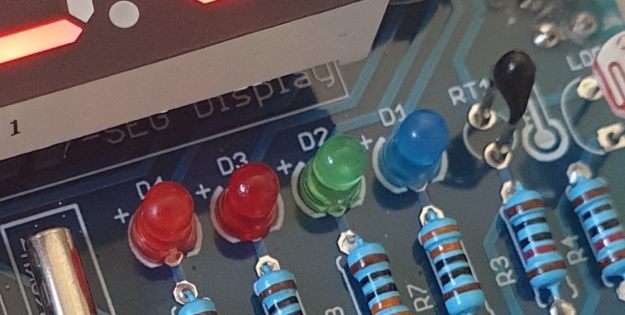
Our shield has four LEDs, as shown below:

They’re labelled D1 through to D4, with D1 on the right-hand side. They are wired to digital outputs D2, D3, D4 and D5 respectively. Again, they can be used with digitalWrite() – so let’s do that now with a quick demonstration of some blinky goodness. Our sketch turns the LEDs on and off in sequential order. You can change the delay by altering the variable x:

void setup() {
  // initialize digital pin LED_BUILTIN as an output.
  pinMode(2, OUTPUT); // LED 1
  pinMode(3, OUTPUT); // LED 2
  pinMode(4, OUTPUT); // LED 3
  pinMode(5, OUTPUT); // LED 4
}

int x = 200;

void loop() {
  digitalWrite(2, HIGH);    // turn on LED1
  delay(x);
  digitalWrite(2, LOW);    // turn off LED1. Process repeats for the other three LEDs
  digitalWrite(3, HIGH);
  delay(x);
  digitalWrite(3, LOW);
  digitalWrite(4, HIGH);
  delay(x);
  digitalWrite(4, LOW);
  digitalWrite(5, HIGH);
  delay(x);
  digitalWrite(5, LOW);
}

And in action:

The Buttons

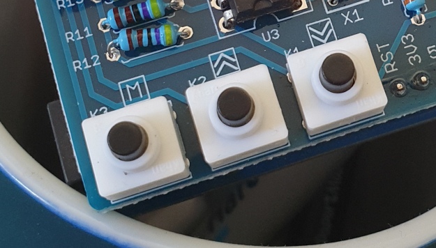
It is now time to pay attention to the three large buttons on the bottom-left of the shield. They look imposing however are just normal buttons, and from right-to-left are connected to digital pins D9, D10 and D11:

They are, however, wired without external pull-up or pull-down resistors so when initialising them in your Arduino sketch you need to activate the digital input’s internal pull-up resistor inside the microcontroller using:

pinMode(pin, INPUT_PULLUP);

Due to this, buttons are by default HIGH when not pressed. So when you press a button, they return LOW. The following sketch demonstrates the use of the buttons by lighting LEDs when pressed:

void setup() {
  // initalise digital pins for LEDs as outputs
  pinMode(2, OUTPUT); // LED 1
  pinMode(3, OUTPUT); // LED 2
  pinMode(4, OUTPUT); // LED 3

  // initalise digital pins for buttons as inputs
  // and initialise internal pullups
  pinMode(9, INPUT_PULLUP); // button K1
  pinMode(10, INPUT_PULLUP); // button K2
  pinMode(11, INPUT_PULLUP); // button K3
}

void loop()
{
  if (digitalRead(9) == LOW)
  {
    digitalWrite(2, HIGH);
    delay(10);
    digitalWrite(2, LOW);
  }

  if (digitalRead(10) == LOW)
  {
    digitalWrite(3, HIGH);
    delay(10);
    digitalWrite(3, LOW);
  }

  if (digitalRead(11) == LOW)
  {
    digitalWrite(4, HIGH);
    delay(10);
    digitalWrite(4, LOW);
  }
}

You can see these in action via the following video:

The Numerical LED Display

Our shield has a nice red four-digit, seven-segment LED clock display. We call it a clock display as there are colon LEDs between the second and third digit, just as a digital clock would usually have:

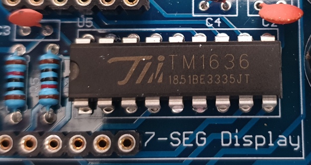
The display is controlled by a special IC, the Titan Micro TM1636:

The TM1636 itself is an interesting part, so we’ll explain that in a separate tutorial in the near future. For now, back to the shield.

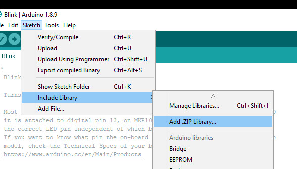
To control the LED display we need to install an Arduino library. In fact the shield needs four, so you can install them all at once now. Download the .zip file from here. Then expand that into your local download directory – it contains four library folders. You can then install them one at a time using the Arduino IDE’s Sketch > Include library > Add .zip library… command:

The supplied library offers five functions used to control the display.

.num(x);

…this displays a positive integer (whole number) between 0 and 9999.

.display(p,d);

… this shows a digit d in location p (locations from left to right are 3, 2, 1, 0)

.time(h,m)

… this is used to display time data (hours, minutes) easily. h is hours, m is minutes

.pointOn();
.pointOff();

… these turn the colon on … and off. And finally:

.clear();

… which clears the display to all off. At the start of the sketch, we need to use the library and initiate the instance of the display by inserting the following lines:

#include <TTSDisplay.h>
TTSDisplay rtcshield;

Don’t panic – the following sketch demonstrates the five functions described above:

#include <TTSDisplay.h>
TTSDisplay rtcshield;

int a = 0;
int b = 0;

void setup() {}

void loop()
{
  // display some numbers
  for (a = 4921; a < 5101; a++)
  {
    rtcshield.num(a);
    delay(10);
  }

  // clear display
  rtcshield.clear();

  // display individual digits
  for (a = 3; a >= 0; --a)
  {
    rtcshield.display(a, a);
    delay(1000);
    rtcshield.clear();
  }
  for (a = 3; a >= 0; --a)
  {
    rtcshield.display(a, a);
    delay(1000);
    rtcshield.clear();
  }

  // turn the colon and off
  for (a = 0; a < 5; a++)
  {
    rtcshield.pointOn();
    delay(500);
    rtcshield.pointOff();
    delay(500);
  }

  // demo the time display function
  rtcshield.pointOn();
  rtcshield.time(11, 57);
  delay(1000);
  rtcshield.time(11, 58);
  delay(1000);
  rtcshield.time(11, 59);
  delay(1000);
  rtcshield.time(12, 00);
  delay(1000);
}

And you can see it in action through the video below:

The LDR (Light Dependent Resistor)

LDRs are useful for giving basic light level measurements, and our shield has one connected to analog input pin A1. It’s the two-legged item with the squiggle on top as shown below:

The resistance of LDRs change with light levels – the greater the light, the less the resistance. Thus by measuring the voltage of a current through the LDR with an analog input pin – you can get a numerical value proportional to the ambient light level. And that’s just what the following sketch does:

#include <TTSDisplay.h>
TTSDisplay rtcshield;

int a = 0;

void setup() {}
void loop()
{
  // read value of analog input
  a = analogRead(A1);
  // show value on display
  rtcshield.num(a);
  delay(100);
}

The Thermistor

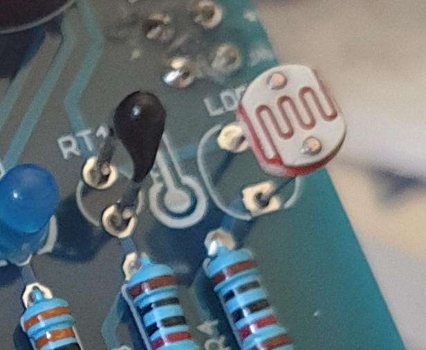
A thermistor is a resistor whose resistance is relative to the ambient temperature. As the temperature increases, their resistance decreases. It’s the black part to the left of the LDR in the image below:

We can use this relationship between temperature and resistance to determine the ambient temperature. To keep things simple we won’t go into the theory – instead, just show you how to get a reading.

The thermistor circuit on our shield has the output connected to analog input zero, and we can use the library installed earlier to take care of the mathematics. Which just leaves us with the functions.

At the start of the sketch, we need to use the library and initiate the instance of the thermistor by inserting the following lines:

#include <TTSTemp.h>
TTSTemp temp;

… then use the following which returns a positive integer containing the temperature (so no freezing cold environments):

.get();

For our example, we’ll get the temperature and show it on the numerical display:

#include <TTSDisplay.h>
#include <TTSTemp.h>

TTSTemp temp;
TTSDisplay rtcshield;

int a = 0;

void setup() {}

void loop() {

  a = temp.get();
  rtcshield.num(a);
  delay(500);
}

And our thermometer in action. No video this time… a nice 24 degrees C in the office:

The Real-Time Clock 

Our shield is fitted with a DS1307 real-time clock IC circuit and backup battery holder. If you insert a CR1220 battery, the RTC will remember the settings even if you remove the shield from the Arduino or if there’s a power blackout, board reset etc:

The DS1307 is incredibly popular and used in many projects and found on many inexpensive breakout boards. We have a separate tutorial on how to use the DS1307, so instead of repeating ourselves – please visit our specific DS1307 Arduino tutorial, then return when finished.

Where to from here? 

We can image there are many practical uses for this shield, which will not only improve your Arduino coding skills but also have some useful applications. An example is given below, that you can use for learning or fun.

Temperature Alarm

This projects turns the shield into a temperature monitor – you can select a lower and upper temperature, and if the temperature goes outside that range the buzzer can sound until you press it.

Here’s the sketch:

#include <TTSDisplay.h>
#include <TTSTemp.h>

TTSTemp temp;
TTSDisplay rtcshield;

boolean alarmOnOff = false;
int highTemp = 40;
int lowTemp = 10;
int currentTemp;

void LEDsoff()
{
  // function to turn all alarm high/low LEDs off
  digitalWrite(2, LOW);
  digitalWrite(4, LOW);
}

void setup() {
  // initalise digital pins for LEDs and buzzer as outputs
  pinMode(2, OUTPUT); // LED 1
  pinMode(3, OUTPUT); // LED 2
  pinMode(4, OUTPUT); // LED 3
  pinMode(5, OUTPUT); // LED 4
  pinMode(6, OUTPUT); // buzzer

  // initalise digital pins for buttons as inputs
  // and initialise internal pullups
  pinMode(9, INPUT_PULLUP); // button K1
  pinMode(10, INPUT_PULLUP); // button K2
  pinMode(11, INPUT_PULLUP); // button K3
}

void loop()
{
  // get current temperature
  currentTemp = temp.get();

  // if current temperature is within set limts
  // show temperature on display

  if (currentTemp >= lowTemp || currentTemp <= highTemp)
    // if ambient temperature is less than high boundary
    // OR if ambient temperature is grater than low boundary
    // all is well
  {
    LEDsoff(); // turn off LEDs
    rtcshield.num(currentTemp);
  }

  // if current temperature is above set high bounday, show red LED and
  // show temperature on display
  // turn on buzzer if alarm is set to on (button K3)

  if (currentTemp > highTemp)
  {
    LEDsoff(); // turn off LEDs
    digitalWrite(4, HIGH); // turn on red LED
    rtcshield.num(currentTemp);
    if (alarmOnOff == true) {
      digitalWrite(6, HIGH); // buzzer on }
    }
  }

  // if current temperature is below set lower boundary, show blue LED and
  // show temperature on display
  // turn on buzzer if alarm is set to on (button K3)

  if (currentTemp < lowTemp)
  {
    LEDsoff(); // turn off LEDs
    digitalWrite(2, HIGH); // turn on blue LED
    rtcshield.num(currentTemp);
    if (alarmOnOff == true)
    {
      digitalWrite(6, HIGH); // buzzer on }
    }
  }
  // --------turn alarm on or off-----------------------------------------------------
  if (digitalRead(11) == LOW) // turn alarm on or off
  {
    alarmOnOff = !alarmOnOff;
    if (alarmOnOff == 0) {
      digitalWrite(6, LOW); // turn off buzzer
      digitalWrite(5, LOW); // turn off alarm on LED
    }
    // if alarm is set to on, turn LED on to indicate this
    if (alarmOnOff == 1)
    {
      digitalWrite(5, HIGH);
    }
    delay(300); // software debounce
  }
  // --------set low temperature------------------------------------------------------
  if (digitalRead(10) == LOW) // set low temperature. If temp falls below this value, activate alarm
  {
    // clear display and turn on blue LED to indicate user is setting lower boundary
    rtcshield.clear();
    digitalWrite(2, HIGH); // turn on blue LED
    rtcshield.num(lowTemp);

    // user can press buttons K2 and K1 to decrease/increase lower boundary.
    // once user presses button K3, lower boundary is locked in and unit goes
    // back to normal state

    while (digitalRead(11) != LOW)
      // repeat the following code until the user presses button K3
    {
      if (digitalRead(10) == LOW) // if button K2 pressed
      {
        --lowTemp; // subtract one from lower boundary
        // display new value. If this falls below zero, won't display. You can add checks for this yourself :)
        rtcshield.num(lowTemp);
      }
      if (digitalRead(9) == LOW) // if button K3 pressed
      {
        lowTemp++; // add one to lower boundary
        // display new value. If this exceeds 9999, won't display. You can add checks for this yourself :)
        rtcshield.num(lowTemp);
      }
      delay(300); // for switch debounce
    }
    digitalWrite(2, LOW); // turn off blue LED
  }
  // --------set high temperature-----------------------------------------------------
  if (digitalRead(9) == LOW) // set high temperature. If temp exceeds this value, activate alarm
  {

    // clear display and turn on red LED to indicate user is setting lower boundary
    rtcshield.clear();
    digitalWrite(4, HIGH); // turn on red LED
    rtcshield.num(highTemp);

    // user can press buttons K2 and K1 to decrease/increase upper boundary.
    // once user presses button K3, upper boundary is locked in and unit goes
    // back to normal state

    while (digitalRead(11) != LOW)
      // repeat the following code until the user presses button K3
    {
      if (digitalRead(10) == LOW) // if button K2 pressed
      {
        --highTemp; // subtract one from upper boundary
        // display new value. If this falls below zero, won't display. You can add checks for this yourself :)
        rtcshield.num(highTemp);
      }
      if (digitalRead(9) == LOW) // if button K3 pressed
      {
        highTemp++; // add one to upper boundary
        // display new value. If this exceeds 9999, won't display. You can add checks for this yourself :)
        rtcshield.num(highTemp);
      }
      delay(300); // for switch debounce
    }
    digitalWrite(4, LOW); // turn off red LED
  }
}

Operating instructions:

  • To set lower temperature, – press button K2. Blue LED turns on. Use buttons K2 and K1 to select temperature, then press K3 to lock it in. Blue LED turns off.
  • To set upper temperature – press button K1. Red LED turns on. Use buttons K2 and K1 to select temperature, then press K3 to lock it in. Red LED turns off.
  • If temperature drops below lower or exceeds upper temperature, the blue or red LED will come on.
  • You can have the buzzer sound when the alarm activates – to do this, press K3. When the buzzer mode is on, LED D4 will be on. You can turn buzzer off after it activates by pressing K3.
  • Display will show ambient temperature during normal operation.

You can see this in action via the video below:

Conclusion

This is a fun and useful shield – especially for beginners. It offers a lot of fun and options without any difficult coding or soldering – it’s easy to find success with the shield and increase your motivation to learn more and make more.

You can be serious with a clock, or annoy people with the buzzer. And at the time of writing you can have one for US$14.95, delivered. So go forth and create something.

A little research has shown that this shield was based from a product by Seeed, who discontinued it from sale. I’d like to thank them for the library.

This post brought to you by pmdway.com – everything for makers and electronics enthusiasts, with free delivery worldwide.

To keep up to date with new posts at tronixstuff.com, please subscribe to the mailing list in the box on the right, or follow us on twitter @tronixstuff.

ESP-13 WiFi Shield Web Server

Description

This tutorial will show you how to setup a simple webserver on your ESP-13 WiFi Shield and display a table of all of the WiFi Access Points within it's range (and refreshed every 5 seconds).
The ESP-13 shield will create it's own WiFi access point, which means that you can take this project anywhere you want to. You do not have to be connected to your home/work WiFi network to see the webpage. The limitation however, is that your device must be within WiFi range of the ESP-13 WiFi shield in order to see the results of the WiFi scan.

Let me show you how to put this project together:
COMING SOON....

ScottC 16 Sep 18:13

Getting Started with the Keyes ESP-13 WiFi Shield

Description

This tutorial will help you get started with the KEYES ESP-13 WiFi Shield.

The ESP-13 WiFi Shield is compatible with an Arduino UNO and has the same form-factor. Essentially this shield will give your Arduino project WiFi capabilities. While it interfaces nicely with the Arduino, it can operate without it. However, if I were planning on using the shield independantly, then I probably would opt for an ESP module rather than a shield.

I bought my shield from Jaycar (CAT.NO: XC4614), however you can get it much cheaper from other online retailers at about a quarter of the price. The instructions on the Jaycar website are not that good, and at first I thought I had bought myself a useless product. It just didn't seem to work regardless of what I tried. There were some tutorials online that gave me hope, only to find that my shield was not quite the same and therefore I did not get the same results. But after countless hours of trial and error and patching various bits of knowledge together, I finally worked out how to use this shield. Everything has fallen into place. And it is easier that you would think... let me show you how.

Parts Required

  1. Arduino UNO (or compatible board)
  2. KEYES ESP-13 WiFi Shield - from Jaycar (Cat. No: XC4614)
  3. USB cable - to connect Arduino to Computer
  4. 4 wires: 4 x Male to Male connectors


Libraries and IDE

Arduino IDE

While there are many Arduino IDE alternatives out there, I would recommend that you use the official Arduino IDE for this project. I used the official Arduino IDE app (v1.8.5) for Windows 10.
Make sure to get the most up-to-date version for your operating system here.


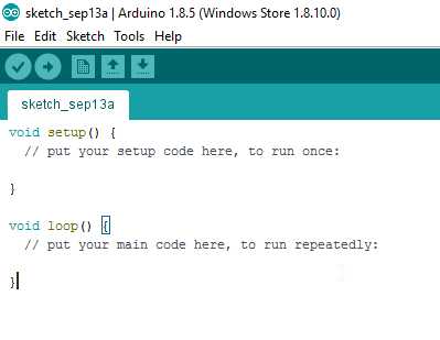
Upload BareMinimum Sketch

Upload a BareMinimum Sketch to the Arduino UNO (or compatible board) before making any connections to the ESP-13. We want to upload the BareMinimum sketch because we don't want the Arduino UNO interfering with our setup in anyway. Here is how to do that:

  1. Start your Arduino IDE
  2. Connect the Arduino UNO to the Computer using a USB cable
  3. Select: File > New (or Ctrl + N)
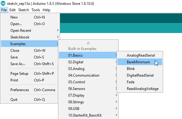
  4. Select: File > Examples > 01.Basics > BareMinimum
  5. Select: Tools > Board > Arduino/Genuino UNO
  6. Select: Tools > Port > COM4 (Your Arduino may be on a different COM port)
  7. Select: Sketch > Upload (or Ctrl + U) - or click on right arrow symbol
  8. After the sketch has uploded. Disconnect the USB cable from the computer/Arduino.


IDE Configuration for ESP-13

Now for the fun part. The ESP-13 WiFi Shield is itself a microcontroller, however, the Arduino IDE is not by default, configured to communicate with or program the ESP-13 WiFi Shield. We are about to change that:

  1. Select File > Preferences from the Arduino IDE menu (or Ctrl+Comma)
  2. Insert the following text into the Additional Boards Manager URLs field:
    If there is a URL in that space already, then insert a comma, and append the URL to the end:

    http://arduino.esp8266.com/stable/package_esp8266com_index.json


  3. Once the URL is added, press OK.
    This will allow us to install the ESP8266 package in the next step.


Installing the ESP8266 board

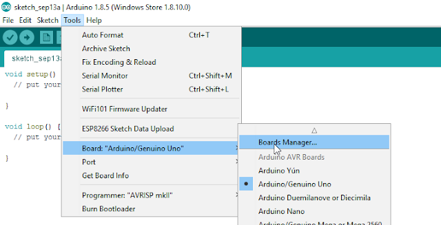
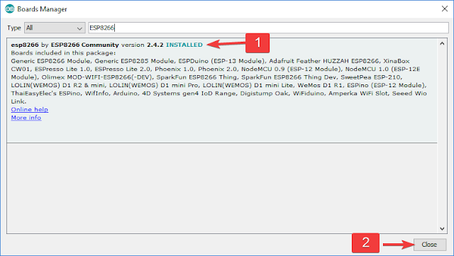
  1. Select: Tools > Board: "xxxx" > Boards Manager
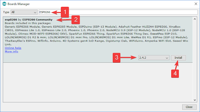
  2. Search for ESP8266 using the Search bar
  3. Select the "esp8266 by ESP8266 Community" board from the list.
  4. Select the latest or most up-to-date version from the drop-down box (eg. 2.4.2)
  5. Press the Install button.
  6. Make sure that the esp8266 board is installed. Then press the "Close" button
  7. Choose the ESPDuino(ESP-13 Module) from the ESP8266 Modules list:
    Tools > Board: "xxxx" > ESPDuino(ESP-13 Module)


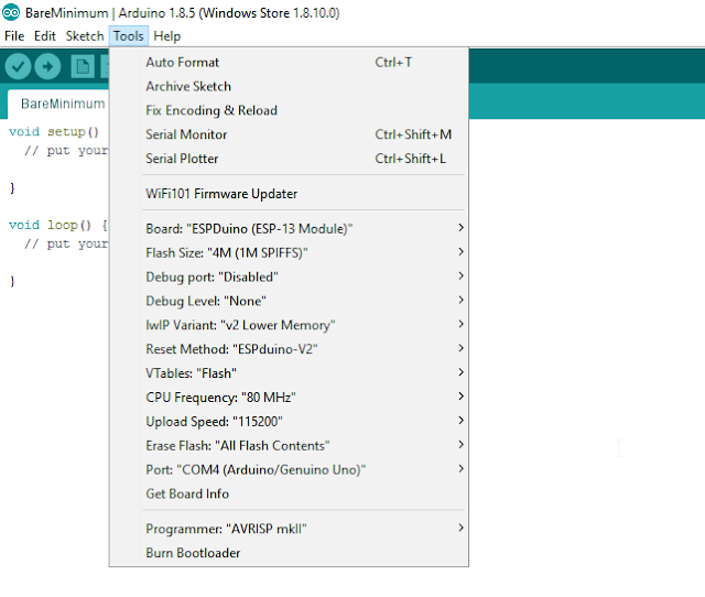
ESP-13 Flash Settings

You will then want to check that you have the following settings in the Tools menu of the Arduino IDE:

  • Board: "ESPDuino (ESP-13 Module)"
  • Flash Size: "4M (1M SPIFFS)"
  • Debug port: "Disabled"
  • Debug Level: "None"
  • IwIP Variant: "v2 Lower Memory"
  • Reset Method: "ESPduino-V2"
  • VTables: "Flash"
  • CPU Frequency: "80MHz"
  • Upload Speed: "115200"
  • Erase Flash: Only Sketch
  • Port: - (we will select that later)

The Arduino IDE is now able to communicate with, and program the ESP-13 WiFi shield.
Now let us have a look at how to use the default AI-Thinker AT-firmware that comes pre-loaded on the shield.


Preparing the WiFi Shield for Communication

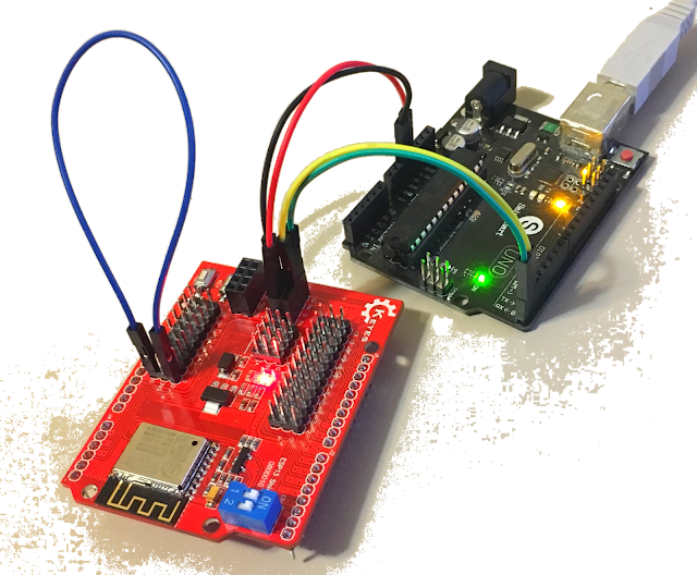
The Keyes ESP-13 WiFi shield comes pre-loaded with AI-Thinker firmware. I thought I just had to place the WiFi shield on top of the Arduino UNO, and I should be able to send through some AT commands via the Serial monitor. Yes - it is a shield, and yes, we will use it as a shield later on, but if you want to use the Serial monitor while the shield is sitting on-top of the Arduino UNO, you will need to make use of the SoftwareSerial library. You can go down this path, but it is cumbersome. There is a better way. We will still need the Arduino UNO, but we need to connect it to the ESP-13 Shield in the following manner:

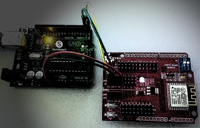
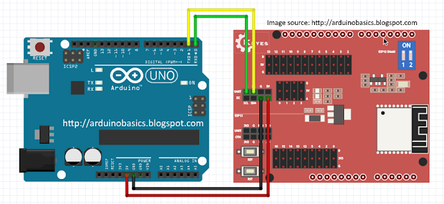
Wire Connections

  1. Make sure that the Arduino UNO is OFF (i.e. not connected to power or USB port)
  2. Place the ESP-13 WiFi shield NEXT TO the Arduino UNO
  3. Connect a Red wire between 5V on Arduino UNO, and 5V (Arduino side) of the ESP-13 shield
  4. Connect a Black wire between GND on Arduino, and G (Arduino side) of the ESP-13 shield
  5. Connect a Green wire between D0(RX) on Arduino, and TX (UART - Arduino side) of ESP-13
  6. Connect a Yellow wire between D1(TX) on Arduino, and RX (UART - Arduino side) of ESP-13
  7. Make sure that both of the switches on the ESP-13 WiFi Shield are in the "ON" position.

Serial Monitor Setup

  1. Plug the USB cable into the computer, and the other end into the Arduino
  2. You should see a Red LED ignite on the ESP-13 Shield.
  3. In your Arduino IDE, make sure the correct COM port is selected:
    Tools > Port > COM4 (Arduino/Genuino UNO) - your port may be different.
  4. The IDE recognises that an Arduino is using that COM port, even though ESP-13 Board selected
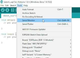
  5. Open the Serial Monitor: Tools > Serial Monitor (or Ctrl + Shift + M)
  6. Select: Both NL & CR from the drop-down box at the bottom right side of the Serial Monitor.
  7. Select: 115200 baud from the other drop-down box in the Serial Monitor window.
  8. Press the RESET (RST) button on the bottom left of the ESP-13 WiFi Shield.
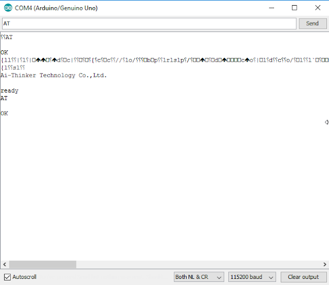
  9. You may see some garbled information come through, but you should see "Ai-Thinker Technology Co.,Ltd" and "ready" messages in the debug window.
  10. You can now send through your AT-commands to the ESP-13 WiFi shield.


Using default AI-Thinker AT-firmware

Now is a good time to test the AI-Thinker AT-firmware. It is possible to program the Arduino to send a sequence of AT commands to the ESP-13 WiFi Shield, but for demonstration purposes, I will show you how to send the commands manually via the Serial monitor.

  1. If you see "ready" within the Serial Monitor window, the ESP-13 is ready to receive AT commands.
  2. Type: AT into the box at the top and press the Send button (or Enter)
  3. You should now see the AT command in the debug window, and a response "OK"

If you received the OK message, then your communication with the ESP-13 was successful.
A good list of AT commands and explanations can be found here.
Another list of AT commands can be found here.

The commands allow you to test, query and configure the ESP-13 shield. Essentially a command-line interface. Try out the following commands to get a feel for these functions/queries. The commands are in bold, and I placed some of the responses that I got in the line below.

  1. AT
    Response: OK

  2. AT+RST
    This resets the ESP-13 board. It provides some info about the board.

  3. AT+GMR
    AT version: 0.40.0.0 (Aug 8 2015)
    SDK version: 1.3.0
    Ai-Thinker Technology Co.,Ltd.
    Build:1.3.0.2 Sep 11 2015

  4. AT+CIFSR
    +CIFSR:APIP, "192.168.4.1"

  5. AT+CWMODE?
    +CWMODE:2 [1=STA, 2=AP, 3=BOTH]

  6. AT+CWLAP
    ERROR

  7. AT+CWMODE=3

  8. AT+CWLAP
    +CWLAP:(3,"MYACCESSPOINT", -53, "xx:xx:xx:xx:xx:xx",6,-12)

So there you go. Now you have everything need to configure your ESP-13 WiFi shield. Once you are tired of playing around with AT commands, I will show you how to re-program and upload sketches to the ESP-13 WiFi Shield, and use it the way it was designed to be used (i.e. as a shield). To upload sketches to the Shield, you will need one extra wire. But I think that deserves to be another tutorial. Stay tuned.

Summary

In this tutorial, I showed you how to configure your Arduino IDE for the ESP-13 shield. I also explained how to wire the ESP-13 WiFi shield so that you can communicate with it using the Serial monitor. I hope this tutorial helped you in some way. If it did, please let me know in the comments below. I will be following up with another tutorial, which will show you how to upload sketches to the ESP-13 WiFi Shield, and free it from your computer.


Social Media

You can find me on various social networks:


Visit my ArduinoBasics Google + page.
Follow me on Twitter by looking for ScottC @ArduinoBasics.
I can also be found on Pinterest and Instagram.
Have a look at my videos on my YouTube channel.


Getting Started with the Keyes ESP-13 WiFi Shield

Description

This tutorial will help you get started with the KEYES ESP-13 WiFi Shield.
The ESP-13 WiFi Shield is compatible with an Arduino UNO and has the same form-factor. Essentially this shield will give your Arduino project WiFi capabilities. While it interfaces nicely with the Arduino, it can operate without it. However, if I were planning on using the shield independantly, then I probably would opt for an ESP module rather than a shield.
I bought my shield from Jaycar (CAT.NO: XC4614), however you can get it much cheaper from other online retailers at about a quarter of the price. The instructions on the Jaycar website are not that good, and at first I thought I had bought myself a useless product. It just didn't seem to work regardless of what I tried. There were some tutorials online that gave me hope, only to find that my shield was not quite the same and therefore I did not get the same results. But after countless hours of trial and error and patching various bits of knowledge together, I finally worked out how to use this shield. Everything has fallen into place. And it is easier that you would think... let me show you how.


Coming soon......................

Don’t Forget Your Mints When Using This Synthesizer

While synthesizers in the music world are incredibly common, they’re not all keyboard-based instruments as you might be imagining. Especially if you’re trying to get a specific feel or sound from a synthesizer in order to mimic a real instrument, there might be a better style synth that you can use. One of these types is the breath controller, a synthesizer specifically built to mimic the sound of wind instruments using the actual breath from a physical person. Available breath controllers can be pricey, though, so [Andrey] built his own.

To build the synthesizer, [Andrey] used a melodica hose and mouthpiece connected to a pressure sensor. He then built a condenser circuit on a custom Arduino shield and plugged it all into an Arduino Mega (although he notes that this is a bit of overkill). From there, the Arduino needed to be programmed to act as a MIDI device and to interact with the pressure sensor, and he was well on his way to a wind instrument synthesizer.

The beauty of synthesizers is not just in their ability to match the look and sound of existing instruments but to do things beyond the realm of traditional instruments as well, sometimes for a greatly reduced price point.

Roboshield Helps Your Robot Walk and Talk

The joy of building robots comes from being able to imbue them with as much or as little personality and functionality as you wish during the design and build process. While creative flair and originality is always a good thing, there’s a lot of basic needs many robots have in common with each other, so where possible it’s good to avoid reinventing the wheel so more time can be spent on more advanced features. Roboshield aims to help make the basics easy so you can let your robot freak flag fly!

At its core, it’s an Arduino shield that packs in a host of hardware to get your robot up and running. As far as motion is concerned, a PCA9685 module is used to allow the control of 8 servos, plus there’s a TB6621FNG dual motor speed controller that offers both speed control and forward/reverse. That’s enough to get your electronic buddy scooting about the floor and waving its arms in the air.

The party piece, however, is the Vstamp text-to-speech module. This device produces a beautiful cliche electronic voice, which your robot is legally required to use to recite Asimov’s Laws of Robotics. Overall, it’s a tidy project that can take the hassle out of getting your robot design up and running, leaving you to focus on the fun bits like death rays and tractor beams. We can’t wait to see it powering the next wave of sassy DIY robots.

Stomping On Microcontrollers: Arduino Mega Guitar Effects Pedal

Effects pedals: for some an object of overwhelming addiction, but for many, an opportunity to hack. Anyone who plays guitar (or buys presents for someone who does) knows of the infinite choice of pedals available. There are so many pedals because nailing the tone you hear in your head is an addictive quest, an itch that must be scratched. Rising to meet this challenge are a generation of programmable pedals that can tweak effects in clever ways.

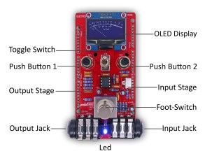
With this in mind, [ElectroSmash] are back at it with another open source offering: the pedalSHIELD MEGA. Aimed at musicians and hackers who want to learn more about audio, DSP and programming, this is an open-hardware/open-software shield for the Arduino MEGA which transforms it into an effects pedal.

The hardware consists of an analog input stage which amplifies and filters the incoming signal before passing it to the Arduino, as well as an output stage which does the DAC-ing from the Arduino’s PWM outputs, and some more filtering/amplifying. Two 8-bit PWM outputs are used simultaneously to make pseudo 16-bit resolution — a technique you can read more about in their handy forum guide.

The list of effects currently implemented covers all the basics you’d expect, and provides a good starting point for writing custom effects. Perhaps a library for some of the commonly used config/operations would be useful? Naturally, there are some computational constraints when using an Arduino for DSP, though it’s up to you whether this is a frustrating fact, or an opportunity to write some nicely optimised code.

[ElectroSmash] don’t just do pedals either: here’s their open source guitar amp.

The Adafruit Feather Is A Thing

A few years ago, Adafruit launched the Feather 32u4 Basic Proto. This tiny development board featured — as you would expect — an ATMega32u4 microcontroller, a USB port, and a battery charging circuit for tiny LiPo batteries. It was, effectively, a small Arduino clone with a little bit of extra circuitry that made it great for portable and wearable projects. In the years since, and as Adafruit has recently pointed out, the Adafruit Feather has recently become a thing. This is a new standard. Maxim is producing compatible ‘wings’ or shields. If you’re in San Fransisco, the streets are littered with Feather-compatible boards. What’s the deal with these boards, and why are there so many of them?

The reason for Adafruit’s introduction of the Feather format was the vast array of shields, hats, capes, clicks, props, booster packs, and various other standards. The idea was to bring various chipsets under one roof, give them a battery charging circuit, and not have a form factor that is as huge as the standard Arduino. The Feather spec was finalized and now we have three-phase energy monitors, a tiny little game console, LoRaWAN Feathers, and CAN controllers.

Of course, the Feather format isn’t just limited to Adafruit products and indie developers. The recently introduced Particle hardware is built on the Feather format, giving cellular connectivity to this better-than-Arduino format. Maxim is producing some development boards with the same format.

So, do we finally have a form factor for one-off embedded development that isn’t as huge or as wonky as the gigantic Arduino with weirdly offset headers? It seems so.

Tracktorino Shields You From Poor Interfaces

On-screen controls in a digital audio workstation expand the power of a DJ or musician, but they are not intuitive for everyone. The tactility of buttons, knobs, sliders and real-world controls feels nothing like using a mouse, trackpad, or even a touchscreen. Unfortunately, devices meant to put control into a DJs hands can be unavailable due to location or cost. [Gustavo Silveira] took charge of the situation so he could help other DJs and musicians take control of their workstations with a customized MIDI interface for Traktor DJ software.

MIDI is a widely used serial protocol which has evolved from a DIN connector to USB, and now it is also wireless. This means that the Traktorino is not locked to Traktor despite the namesake. On the Hackaday.io page, there’s even a list of other workstations it will work with, but since many workstations, all the good ones anyway, accept MIDI hardware like this, the real list is a lot longer.

The custom circuit board is actually a shield. Using an Arduino UNO, the current poster child of the Arduino world, opens up the accessibility for many people who don’t know specialized software. A vector drawing for a lasercut enclosure is also included. This means that even the labeling on the buttons are not locked into English language.

Here’s another project which combined laser cutting and MIDI to make some very clever buttons or turn your DIN MIDI connector into USB.

Make Your Own Arduino Header Pins

There are two kinds of people in the world (and, no, this isn’t a binary joke). People who love the Arduino, and people who hate it. If you’ve ever tried to use a standard prototype board to mount on an Arduino, you’ll know what kind of person you are. When you notice the pins aren’t on 0.1 inch centers, you might think, “What the heck were those idiots thinking!” Or, you might say, “How clever! This way the connectors are keyed to prevent mistakes.” From your choice of statement, we can deduce your feelings on the subject.

[Rssalnero] clearly said something different. We weren’t there, but we suspect it was: “Gee. I should 3D print a jig to bend headers to fit.” Actually, he apparently tried to do it by hand (we’ve tried it, too). The results are not usually very good.

He created two simple 3D printed jigs that let you bend an 8-pin header. The first jig bends the correct offset and the second helps you straighten out the ends again. You can see the result in the picture above.

[Rssalnero] notes that the second jig needed reinforcement, so it is made to take 8 pins to use as fulcrums. Probably doesn’t hurt to print the jigs fairly solid and using harder plastic like ABS or PETG, too. Even if you don’t have a 3D printer, this is about a 15 or 30 minute print on any sort of reasonable printer, so make a friend. Worst case, you could have one of the 3D printing vendors make it for you, or buy local.

We love little tool hacks like this. If you are too lazy to snap 8 pins off a 40 pin strip, maybe you’d like some help. If you’d rather go with a custom PC board, you might start here.


Filed under: Arduino Hacks, tool hacks