A Repeater for WWVB
For those living in the continental US who, for whatever reason, don’t have access to an NTP server or a GPS device, the next best way to make sure the correct time is known is with the WWVB radio signal. Transmitting out of Colorado, the 60-bit 1 Hz signal reaches all 48 states in the low-frequency band and is a great way to get a clock within a few hundred nanoseconds of the official time. But in high noise situations, particularly on the coasts or in populated areas these radio-based clocks might miss some of the updates. To keep that from happening [Mike] built a repeater for this radio signal.
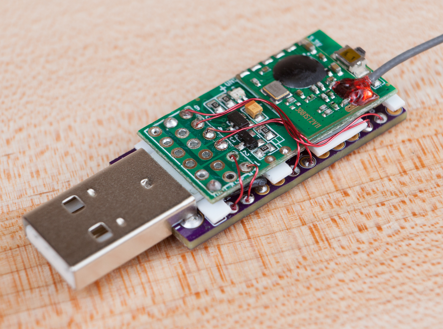
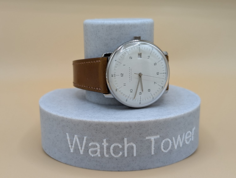
The repeater works by offloading most of the radio components to an Arduino. The microcontroller listens to the WWVB signal and re-transmits it at a lower power to the immediate area, in this case no further than a few inches away or enough to synchronize a few wristwatches. But it has a much better antenna for listening to WWVB so this eliminates the (admittedly uncommon) problem of [Mike]’s watches not synchronizing at least once per day. WWVB broadcasts a PWM signal which is easy for an Arduino to duplicate, but this one needed help from a DRV8833 amplifier to generate a meaningfully strong radio signal.
Although there have been other similar projects oriented around the WWVB signal, [Mike]’s goal for this was to improve the range of these projects so it could sync more than a single timekeeping device at a time as well as using parts which are more readily available and which have a higher ease of use. We’d say he’s done a pretty good job here, and his build instructions cover almost everything even the most beginner breadboarders would need to know to duplicate it on their own.