Posts with «rfid» label

Kids’ Jukebox Based on Arduino with RFID

Consumer electronics aimed at young children tend to be quite janky and cheap-looking, and they often have to be to survive the extreme stress-testing normal use in this situation. You could buy a higher quality item intended for normal use, but this carries the risk of burning a hole in the pockets of the parents. To thread the needle on this dilemma for a child’s audiobook player, [Turi] built the Grimmboy for a relative of his.

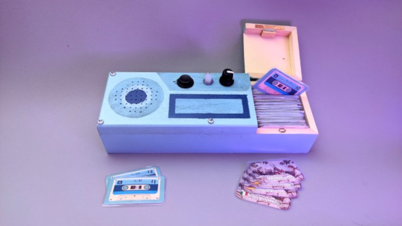
Taking its name from the Brothers Grimm, the player is able of playing a number of children’s stories and fables in multiple languages, with each physically represented by a small cassette tape likeness with an RFID tag hidden in each one. A tape can be selected and placed in the player, and the Arduino at the center of it will recognize the tag and play the corresponding MP3 file stored locally on an SD card. There are simple controls and all the circuitry to support its lithium battery as well. All of the source code that [Turi] used to build this is available on the project’s GitHub page.

This was also featured at the Arudino blog as well, and we actually featured a similar project a while ago with a slightly different spin. Both are based on ideas from Tonuino, an open source project aimed at turning Arduinos into MP3 players. If you’re looking to build something with a few more features, though, take a look at this custom build based on the RP2040 microcontroller instead.

Hack a Day 17 Dec 06:00

Son of Rothult

We are continuously inspired by our readers which is why we share what we love, and that inspiration flows both ways. [jetpilot305] connected a Rothult unit to the Arduino IDE in response to Ripping up a Rothult. Consider us flattered. There are several factors at play here. One, the Arduino banner covers a lot of programmable hardware, and it is a powerful tool in a hardware hacker’s belt. Two, someone saw a tool they wanted to control and made it happen. Three, it’s a piece of (minimal) security hardware, but who knows where that can scale. The secure is made accessible.

The Github upload instructions are illustrated, and you know we appreciate documentation. There are a couple of tables for the controller pins and header for your convenience. You will be compiling your sketch in Arduino’s IDE, but uploading through ST-Link across some wires you will have to solder. We are in advanced territory now, but keep this inspiration train going and drop us a tip to share something you make with this miniature deadbolt.

Locks and security are our bread and butter, so enjoy some physical key appreciation and digital lock love.

Capture the Flag, Along with the Game Data

With events of all sizes on hold and live sports mostly up in the air, it’s a great time to think of new ways to entertain ourselves within our local circles. Bonus points if the activity involves running around outside, and/or secretly doubles as a team-building exercise, like [KarelBousson]’s modernized version of Capture the Flag.

Much like the original, the point of this game is to capture the case and keep it for as long as possible before the other team steals it away. Here, the approach is much more scientific: the box knows exactly who has it and for how long, and the teams get points based on the time the case spends in any player’s possession.

Each player carries an RFID tag to distinguish them from each other. Inside the case is an Arduino Mega with a LoRa shield and a GPS unit. Whenever the game is afoot, the case communicates its position to an external Raspi running the game server.

If you haven’t met LoRa yet, check out this seven-part introductory tutorial.

An RFID-powered seating chart for your wedding

Seating charts at weddings and other formal events are usually handled by small cards at each table, but Gabrielle Martinfortier had other plans. 

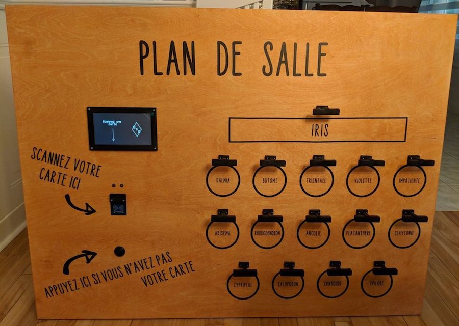
For her big event, she along with help from her now-husband and friends constructed a seating arrangement on a 3’ x 4’ wood canvas, equipped with a 7” TFT display and an RFID reader. An Arduino Mega serves as the brains of the device, taking advantage of its expanded IO capabilities to control an LED assembly over each table on the chart.

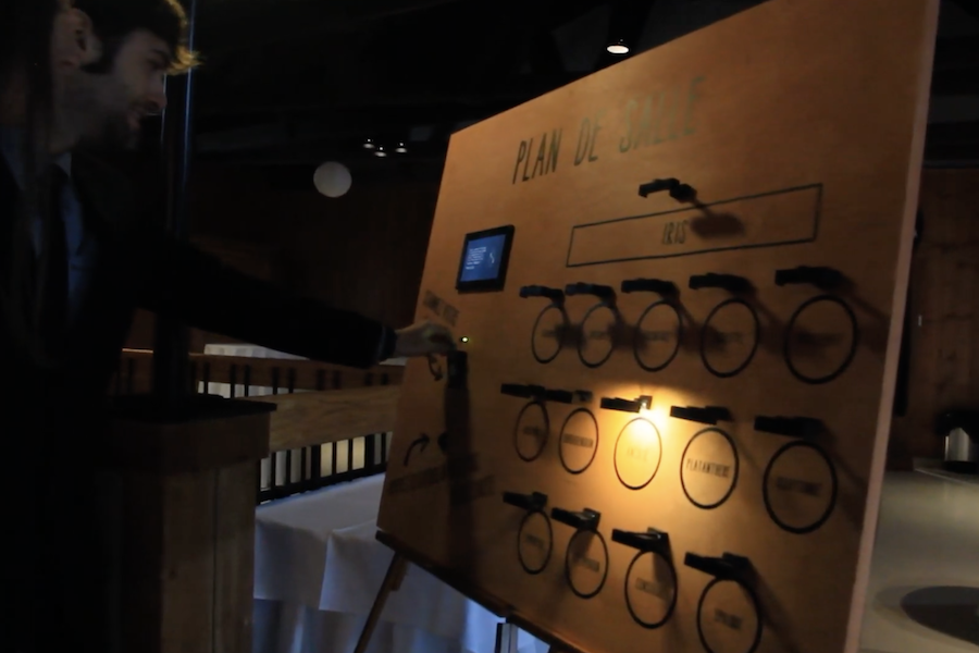
Wedding guests simply had to present the card they received with the invitation, then their proper table was lit. As seen in the video below, this eliminated seating confusion, and provided a bit of extra entertainment for those involved. 

I wanted to make something special for my wedding tables chart, and I thought this was a good way of making it personal, as it reflects my love (addiction) for electronic projects.

So the plan was to make a big wood panel with the plan of the room on it, including, of course, the tables and their names (they are plant names, in French). The guests received a card with an RFID sticker on it along with their invitation. On the back of the card was written (in French) something like “This card is of great importance, keep it safe and carry it on you at the wedding.” I didn’t want them to know what it was for until the wedding.

The chart has several elements  a TFT display, an RFID reader, a green LED and a red LED, a push button and one strip of 3 LEDs for each table. When the RFID tags are scanned, the green LED turns on if it is recognized, and a personalized message is displayed on the screen, including the name of the table where the guest is seated. In addition, the LED strip associated with the table is turned on, shedding light on the table on the room’s plan. If the card is misread or unrecognized, the red LED is turned on with an “access denied” message on the screen. The button is for those who did not succeed in not losing or forgetting the card. It displays a message on the screen, asking them to go to the bar and say something like “I am not reliable,” in exchange of which they get a backup chart to find their seat.

I changed a few things along the way: I wanted to paint the wood panel but changed my mind because I was scared I’d make a mess and have to start over with a new panel. Since I have a circuit machine I decided to make the writings and drawings with vinyl.

I also had a 20×04 character LCD screen in the beginning, but I upgraded to a 7″ TFT screen because it’s bigger and not as limiting in terms of message length.

An Arduino-based RFID tag system perfect for escape rooms

As seen here, “Annaane!” has come up with what could form the guts of a very interesting escape room puzzle. 

Her build features four RFID card readers, which cause an Arduino Uno to release a door lock or other device via a 5V relay, only when the corresponding tags are arranged correctly.

From the looks of the video below, the design is very much a prototype, but could easily be morphed into an arrangement to frustrate and entertain participants. As noted, the project uses all but the TX and RX pins on the Uno, but this could be expanded by using a Mega or an I2C port expander. 

Code for the system can be found on GitHub.

Held Captive by Arduino and Multiple RFID Readers

If you’re the kind of person who has friends, and/or leaves the confines of the basement from time to time, we hear that these “Escape Rooms” are all the rage. Basically you get locked into a room with a couple other people and have to solve various problems and puzzles until you’ve finally made enough progress that they let you out. Which actually sounds a lot like the working conditions here at Hackaday HQ, except they occasionally slip some pizza rolls under the door for us which is nice.

Whichever side you find yourself on in one of these lighthearted hostage situations, knowledge of this multi-tag RFID lock created by [Annaane] may come in handy. By connecting multiple MFRC522 RFID readers to an Arduino Uno, she’s come up with a method of triggering a device (like an electronic door lock) only when the appropriate combination of RFID tags have been arranged. With a little imagination, this allows for some very complex puzzle scenarios which are sure to keep your prisoners enthralled until you can lower the lotion down to them.

Her code allows you to configure the type and number of RFID cards required to trigger one of the Arduino’s digital pins, which usually would be connected to a relay to fire off whatever device you want. The Arduino sketch is also setup to give “hints” to the player by way of a status LED: fast blinking let’s you know the tag scanned is wrong, and slow blinking means you don’t have enough scanned in yet.

The video after the break shows some highlights of the build, as well as a quick demonstration of how both the RFID “combination” and manual override can be used to trigger the attached relay.

Hackers do love RFID. Using them for physical access control is a fairly common project around these parts, and we’ve even seen similar setups for the digital realm.

RFID Unlock Your PC, Because You’re 1337

Ever wanted to feel like one of those movie hackers from the late 90s? Yes, your basement’s full of overclocked Linux rigs and you’ve made sure all your terminal windows are set to green text on a black background, but that’s not always enough. What you need is an RFID tag that unlocks your PC when you touch the reader with your RFID cardOnly then may you resume blasting away at your many keyboards in your valiant attempts to hack the mainframe.

[Luke] brings us this build, having wanted an easier way to log in quickly without foregoing basic security. Seeing as an RC522 RFID reader was already on hand, this became the basis for the project. The reader is laced up with a Sparkfun Pro Micro Arduino clone, with both devices serendipitously running on 3.3V, obviating the need for any level shifters. Code is simple, based on the existing Arduino RC522 library. Upon a successful scan of the correct tag, the Arduino acts as a HID keyboard and types the user’s password into the computer along with a carriage return, unlocking the machine. Simple!

Overall, it’s a tidy build that achieves what [Luke] set out to do. It’s something that could be readily replicated with a handful of parts and a day’s work. If you’re interested in the underlying specifics, we’ve discussed turning Arduinos into USB keyboards before.

Hack a Day 18 Mar 06:00

RFID Stethoscope Wheezes and Murmurs for Medical Training

You’d think that with as many sick people as there are in the world, it wouldn’t be too difficult for a doctor in training to get practice. It’s easy to get experience treating common complaints like colds and the flu, but it might take the young doctor a while to run across a dissecting abdominal aortic aneurysm, and that won’t be the time for on the job training.

Enter the SP, or standardized patient – people trained to deliver information to medical students to simulate a particular case. There’s a problem with SPs, though. While it’s easy enough to coach someone to deliver an oral history reflecting a medical condition, the student eventually needs to examine the SP, which will reveal none of the signs and symptoms associated with the simulated case. To remedy this, [Chris Sanders] and [J Scott Christianson] from the University of Missouri developed an open-source RFID stethoscope to simulate patient findings.

This is one of those “why didn’t I think of that?” ideas. A cheap stethoscope is fitted with an Arduino, and RFID reader, and a small audio board. RFID tags are placed at diagnostic points over an SP’s chest and abdomen. When the stethoscope is placed over a tag, a specific sound file is fetched from an SD card and played over earbuds. The student doesn’t have to ask, “What am I hearing?” anymore – the actual sound of bruits or borborygmi are heard.

We can easily see expanding this system – RFID tags that trigger a faux ultrasound machine to display diagnostic images, or tiny OLED screens displaying tagged images into an otoscope. A good place to start expanding this idea might be this digital stethoscope recorder and analyzer.


Filed under: Medical hacks

Huge Interactive Crossword

Give kids some responsible and challenging tasks, and you’d be surprised at the results. The “Anything Goes” exhibit at the National Museum in Warsaw was aimed as a museological and educational experiment. A group of 69 children aged 6–14 was divided into teams responsible for preparing the main temporary exhibition at the museum. Over six months, they worked on preparing the exhibition during weekly four-hour meetings. They prepared scripts, provided ideas for multimedia presentations, and curated almost 300 works for display. One of those was [Robert Mordzon]’s Giant Interactive Crossword.

The build is in two parts. The letter tiles, which have embedded RFID tags, obviously look like the easiest part of the build. The table, looking at the video (after the break), probably needed a lot more effort and labour. It is built in two halves to make construction easier. There are a 130 boxes that need to be filled in with the right letters to complete the crossword. Each box contains a bunch of electronics consisting of an Arduino Nano, a RFID Reader and a bunch of sixteen WS2812B LEDs, all assembled on a custom PCB. Do the math, and you’ll figure out that there’s 2080 LEDs, each capable of sipping 60 mA at full brightness. That’s a total current requirement of almost 125 amps at 5 V. Add in all the Arduino’s, and [Robert] needed a beefy 750 W of power, supplied via four switch mode power supplies.

Each Arduino Nano is a slave on the I²C bus. The I²C master is an Arduino Mega 2560, which in turn communicates with a computer over serial. When a box is empty, the LEDs are dim, when a wrong letter is placed, they turn Red, and when the right letter is placed, they turn Green. If a word gets completed, a special word animation is played. This information is also passed on to the computer, which then projects an animation related to the word on a giant wall screen. Upon the crossword getting completed, the table erupts in to a sound (via the computer) and light “disco” show and also reveals the main motto of this section of the exhibit – “Playing the Hero”.


Filed under: Arduino Hacks

Arduino based Security Project Using Cayenne


Description

This is an Arduino based home security project that uses the power of "Cayenne" for extraordinary capabilities.

Cayenne Beta

Cayenne is a new IoT drag and drop platform originally released for the Raspberry Pi, but now available for Arduino. Cayenne makes the task of connecting your Arduino to the internet as simple as possible. All of the complexity of internet connectivity is hidden within the Cayenne library.

You can easily create a Network of Arduinos and build an IoT system which can be managed and operated within the Cayenne dashboard. This dashboard is accessible through your browser or via the Cayenne smart phone app (on IOS or Android).

The feature I liked the most, was the ability to change the position of sensors or actuators on the Arduino without having to re-upload Arduino code. I could manage the changed position from within the Cayenne platform. The other feature that I liked was the ability to setup actions based on custom triggers. You can use Cayenne to trigger a whole range of functions, for example: play a sound, move a motor, light up an LED, or to send alert notifications via email or SMS.

Cayenne is in Beta at the moment, so there are a few minor bugs here and there, but overall - I give it a thumbs up - it is definitely worth checking out.
 

Here is a link to the Cayenne Beta Program:
**Cayenne Beta Link**


              Source: myDevices Media Kit


Home Security Project Summary

In order to fully experience this new IoT platform, I decided to create a project to really put it through its paces. This is what my Security Project will need:

  1. It will use two Arduinos, one connected to the internet via an Ethernet shield, and the other via WIFI.
  2. Two detectors - a PIR sensor and a laser trip wire.
  3. If the sensors are tripped, the person has 10 seconds to present an RFID tag to the Grove RFID reader:
    • If a valid RFID tag is SUCCESSFULLY presented within the time limit, a nice personalised greeting will be played to that person using a Grove - Serial MP3 player
    • If a valid RFID FAILS to be presented within the time limit, an Alarm will sound, and I will be notified of the intrusion via an SMS alert.
  4. The Cayenne dashboard will show the status of the sensors, and I will have full control over my security system via the web interface (or smartphone app).
  5. The sensors will be attached to a different Arduino to that of the Grove MP3 player and the RFID tag reader, which means that there will have to be some level of communication between the two Arduinos. In fact, the cross communication will be vital to the success of this project.


Project Video


Flow Diagrams:

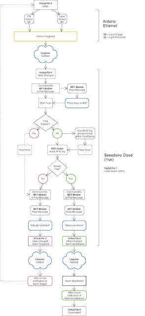
Main Flow Diagram

The following flow diagram shows the Security project process. It is a high level view of the decisions being made by each Arduino in response to various events.  


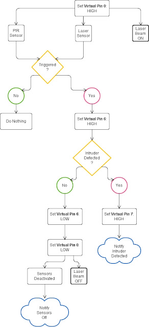
Triggers Flow Diagram

The following flow diagram aims to highlight the various triggers set up within Cayenne to get this Security system to work.  


Arduino IDE and Library Downloads

You will need an Arduino IDE to upload code to the Arduino and the Seeeduino Cloud.
Here is the link to the Arduino IDE: Arduino IDE - download location

The Cayenne service requires that you download and install the Cayenne Library into your Arduino IDE.
You can get the Cayenne Library from here: Cayenne Library File - Download


Cayenne Connectivity Setup

The Seeeduino Cloud needs to be prepared for use with Cayenne.
Normal operating/setup instructions can be found here: Seeeduino Cloud WIKI page
 
Once you have successfully connected Seeeduino Cloud to your WIFI network, you can add it to the Cayenne Dashboard by making the following selections from within the Cayenne Web application:

  1. Add New
  2. Device/Widget
  3. Microcontrollers
  4. Arduino
  5. Ensure Seeeduino Cloud is connected to WIFI network - the select the NEXT button
  6. Select - Arduino Yun: Built-in Ethernet - ticked
  7. Providing you have already installed the Cayenne library as described above - you should be able to copy and paste the code to the Arduino IDE and upload to the Seeeduino Cloud.
  8. If successful, you should see the Arduino Yun board appear within the Cayenne Dashboard. If not, then seek help within the Cayenne forum.


The Arduino UNO with WIZNET 5100 - Ethernet Shield
also needs to be prepared with Cayenne

  1. Add New
  2. Device/Widget
  3. Microcontrollers
  4. Arduino
  5. Ensure Arduino is powered, and Ethernet shield is connected to your internet router via an Ethernet cable
  6. Select - Arduino Uno: Ethernet Shield W5100 - ticked
  7. Copy and paste the code to the Arduino IDE and upload to the Arduino UNO.
  8. If successful, you should see the Arduino Uno board appear within the Cayenne Dashboard. If not, then seek help within the Cayenne forum.


If you have the Ethernet shield with the WIZNET 5200 chip, then you may need to download a specific Ethernet library in addition to the Cayenne library.
 
Just follow the instructions within the Automatically generated sketch provided - when you select your specific Arduino/Ethernet/WIFI shield combination. If you need further instructions on connecting your device to Cayenne - then please visit the myDevices website for the online documentation.


ARDUINO CODE (1)


Code for Arduino UNO with Ethernet Shield:

The following code will need to be uploaded to the Arduino UNO:


ARDUINO CODE (2)


Code for Seeeduino Cloud:

The following code will need to be uploaded to the Seeeduino Cloud:


Fritzing diagram (1)


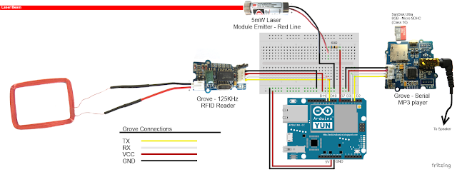
Fritzing diagram for Arduino UNO with Ethernet

Please click on the picture below for an enlarged version of this fritzing diagram


Fritzing diagram (2)


Fritzing diagram for Seeeduino Cloud

Please click on the picture below for an enlarged version of this fritzing diagram


Cayenne Dashboard Setup - GUI


The Arduino code only provides half of the functionality of this project. The Cayenne Dashboard needs to be setup to provide the rest of the functionality. The following instructions will show you how to add each of the widgets required for this Home Security project.


Arduino Ethernet - Master Switch

The master switch allows me to turn the security system on and off. When I turn the MASTER SWITCH ON, the laser beam will turn on, and the sensors will start monitoring the area for intruders. This widget is NOT associated with a physical switch/sensor on the Arduino - it uses virtual channel 0. We need to add the Master switch to the dashboard:


  1. Add New
  2. Device/Widget
  3. Actuators
  4. Generic
  5. Digital Output - Control a Digital Output
  6. Widget Name: Master On Off Switch
  7. Select Device: Arduino Ethernet
  8. Connectivity: Virtual
  9. Pin: V0
  10. Choose Widget: Button
  11. Choose Icon: Valve
  12. Step2: Add Actuator
We will add a trigger later to get this button to automatically turn the Laser beam on.


Arduino Ethernet - PIR Sensor

This sensor will be used to detect movement in the room. If a person walks into the room, this sensor will detect movement, and will trigger a message to be played on the Grove Serial MP3 player. The message will aim to get the person to identify themselves. They identify themselves by placing their RFID tag in close proximity to the Grove RFID reader. If the tag is valid, a "Welcome home" message is played on the Grove MP3 player. If a valid tag is not presented to the reader within 10 seconds, an Alarm will go off ("Alarm sound" played on Grove MP3 player.)
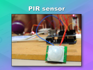
The PIR sensor is connected to digital Pin 6 of the Arduino, however, it is mapped to virtual pin 1 for better synchronisation with the Cayenne dashboard. This was done to capture ALL detections - as the PIR sensor could change from a LOW to HIGH and back to LOW state in between a Cayenne state check - and therefore, Cayenne could miss this motion detection.. Therefore we need to assign the PIR sensor to a virtual channel in the following way:
  1. Add New
  2. Device/Widget
  3. Sensors
  4. Motion
  5. Digital Motion Sensor - Motion Detector
  6. Widget Name: PIR sensor
  7. Select Device: Arduino Ethernet
  8. Connectivity: Virtual
  9. Pin: V1
  10. Choose Widget: 2-State Display
  11. Choose Icon: Light
  12. Step2: Add Sensor
  13. Select Settings from the PhotoResistor
  14. Choose Display: Value
  15. Save


Arduino Ethernet - Photoresistor

This sensor will be used with the laser beam to create a laser tripwire. If the sensor detects a change in light levels (drops below the threshold), it will activate the laser trigger button on the dashboard. The person will then be required to identify themselves etc etc (similar to the motion detection by the PIR sensor). The photoresistor widget will display the raw analog reading from the sensor (connected to A2), but is associated with virtual channel 2. I used a virtual channel for more control over this sensor. To add the Photoresistor to the dashboard:

  1. Add New
  2. Device/Widget
  3. Sensors
  4. Luminosity
  5. Photoresistor - Luminosity sensor
  6. Widget Name: PhotoResistor
  7. Select Device: Arduino Ethernet
  8. Connectivity: Virtual
  9. Pin: V2
  10. Choose Widget: Value
  11. Choose Icon: Light
  12. Step2: Add Sensor


Arduino Ethernet - Laser Trigger

The laser trigger is just an indicator that someone tripped the laser beam. The state of this widget is used to notify the Seeeduino that a presence has been detected. This widget is associated with virtual pin 4 on the Arduino UNO with Ethernet.

  1. Add New
  2. Device/Widget
  3. Actuators
  4. Generic
  5. Digital Output - Control a Digital Output
  6. Widget Name: Laser Trigger
  7. Select Device: Arduino Ethernet
  8. Connectivity: Virtual
  9. Pin: V4
  10. Choose Widget: Button
  11. Choose Icon: Lock
  12. Step2: Add Actuator


Arduino Ethernet - Laser Threshold

The laser threshold is used to manually configure the light level at which the laser trigger will trip. When the photoresistor value drops below the threshold value, the laser trigger icon will activate. This allows the threshold value to be updated from the Cayenne dashboard, rather than having to manually adjust the value in the Arduino code. Also, this threshold can be set remotely, in that you don't have to be near the Arduino to change this value. A very useful feature of this Security system. This widget is associated with virtual pin 5 on the Arduino UNO with Ethernet.

  1. Add New
  2. Device/Widget
  3. Actuators
  4. Generic
  5. PWM Output - Control a PWM Output
  6. Widget Name: Laser Threshold
  7. Select Device: Arduino Ethernet
  8. Connectivity: Virtual
  9. Pin: V5
  10. Choose Widget: Slider
  11. Slider Min Value: 0
  12. Slider Max Value: 10
  13. Step2: Add Actuator
The max value of the slider is 10 - due to a current bug in the Cayenne software. Once resolved, this value (as well as the relevant Arduino code) will need to be updated.


Seeeduino Cloud - Presence Detected

The presence detected widget is there to notify the Seeeduino Cloud that a presence has been detected on the Arduino Uno with Ethernet shield. When the PIR sensor detects movement or if the laser tripwire is tripped, Cayenne will change the state of the Presence Detected widget from LOW to HIGH. This is used within the Seeeduino Cloud to trigger the message "Place your keys on the Mat"
. If a valid RFID tag is read by the Grove RFID reader, then this widget's state will change back from HIGH to LOW, and the MasterSwitch will be deactivated - turning the Security system off. This widget is associated with Virtual pin 6 on the Seeeduino Cloud.

  1. Add New
  2. Device/Widget
  3. Actuators
  4. Generic
  5. Digital Output - Control a Digital Output
  6. Widget Name: Presence Detected
  7. Select Device: Seeeduino Cloud
  8. Connectivity: Virtual
  9. Pin: V6
  10. Choose Widget: Button
  11. Choose Icon: Lock
  12. Step2: Add Actuator


Seeeduino Cloud - Intruder Alert

If a valid RFID tag is not read by the Grove RFID reader within 10 seconds of a presence detection event, an alarm will sound, and this widget will be activated. This will trigger a notification event - to notify me of the unauthorised intrusion - via SMS or email. I will also have a visual indicator on the Cayenne dashboard that an intrusion has taken place. This widget is associated with Virtual pin 7 on the Seeeduino Cloud.

  1. Add New
  2. Device/Widget
  3. Actuators
  4. Generic
  5. Digital Output - Control a Digital Output
  6. Widget Name: Laser Trigger
  7. Select Device: Seeeduino Cloud
  8. Connectivity: Virtual
  9. Pin: V7
  10. Choose Widget: Button
  11. Choose Icon: Thermometer
  12. Step2: Add Actuator


Seeeduino Cloud - Laser Beam

The laser beam widget was created to allow for full control over the laser beam. The laser beam can be turned on or off from the Cayenne dashboard, and a connected to digital pin 7 on the Seeeduino Cloud.


  1. Add New
  2. Device/Widget
  3. Actuators
  4. Light
  5. Light Switch - Turn On/Off a Light
  6. Widget Name: xLaser Beam
  7. Select Device: Seeeduino Cloud
  8. Connectivity: Digital
  9. Pin: D7
  10. Choose Widget: Button
  11. Choose Icon: Light
  12. Step2: Add Actuator


Cayenne Triggers

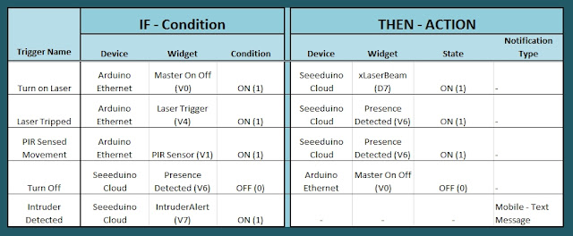
Now that all of the widgets have been added to the Dashboard, there is just one more step to complete the Security System. We need to setup the triggers. These triggers provide a level of automation that is easy to create within Cayenne, but would be very complicated otherwise. I set my triggers up as per the table below. Each row represents one of the triggers within my Cayenne dashboard. If you would like to see an example of how to add a trigger - please have a look at the video at the top of this tutorial.  


Concluding comments

I used many different elements to put this home/office security project together - Multiple Arduinos were connected to the internet, both controlled by a web/smart phone app, cross-communication/synchronisation between the Arduinos, and the use of multiple sensors and modules including a laser beam !
 
This was way more than just a simple PIR sense and alarm project. I now have a personalised greeting and reminder system when I walk in the door. Everyone else has their own personalised greeting. I can enable my Security System remotely, from two blocks away, and if I wanted to - I could enable it from the other side of the world. I know instantly when someone has entered my house/office.... with an SMS alert straight to my phone.
 
This project could easily be extended:

  1. Press a button on my phone to manually trigger/play a specific message/sound/song
  2. Take a picture of the intruder
  3. Introduce fire or leak detection aswell
  4. Add other environmental sensors - Temperature / Humidity
  5. Connect it to lamp/light - creating a security light
I am sure you can think of more things I could do with this system. In fact, why don't you mention your ideas in the comments below.
 
Cayenne was instrumental in getting this project to work. I don't think I would know where to start if I had to do this project without this cool IoT platform. I think I will definitely be trying out a few more projects using Cayenne, and should you want to do the same, then please make sure to join Cayenne Beta:
 
Here is the link you need to get to the right place: Cayenne Beta Link
 

If you like this page, please do me a favour and show your appreciation :

 
Visit my ArduinoBasics Google + page.
Follow me on Twitter by looking for ScottC @ArduinoBasics.
I can also be found on Pinterest and Instagram.
Have a look at my videos on my YouTube channel.


ScottC 02 Sep 05:11
alarm  arduino  arduinobasics  cayenne  laser  mp3  mydevices  pir  rfid  security  sms  tutorial