Posts with «2018 hackaday prize» label

SENSEation Shows The Importance of Good Physical Design

Sensor network projects often focus primarily on electronic design elements, such as architecture and wireless transmission methods for sensors and gateways. Equally important, however, are physical and practical design elements such as installation, usability, and maintainability. The SENSEation project by [Mario Frei] is a sensor network intended for use indoors in a variety of buildings, and it showcases the deep importance of physical design elements in order to create hardware that is easy to install, easy to maintain, and effective. The project logs have an excellent overview of past versions and an analysis of what worked well, and where they fell short.

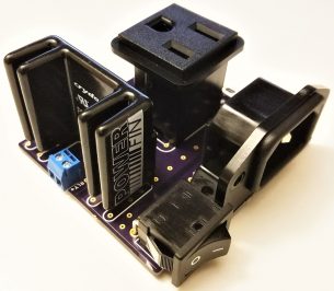
One example is the power supply for the sensor nodes. Past designs used wall adapters to provide constant and reliable power, but there are practical considerations around doing so. Not only do power adapters mean each sensor requires some amount of cable management, but one never really knows what one will find when installing a node somewhere in a building; a power outlet may not be nearby, or it may not have any unoccupied sockets. [Mario] found that installations could take up to 45 minutes per node as a result of these issues. The solution was to move to battery power for the sensor nodes. With careful power management, a node can operate for almost a year before needing a recharge, and removing any cable management or power adapter meant that installation time dropped to an average of only seven minutes.

That’s just one example of the practical issues discovered in the deployment of a sensor network in a real-world situation, and the positive impact of some thoughtful design changes in response. The GitHub repository for SENSEation has all the details needed to reproduce the modular design, so check it out.

An Unmanned Ground Vehicle, Compatable With An Arduino

Building your own robot is something everyone should do, and [Ahmed] has already built a few robots designed to be driven around indoors. An indoor robot is easy, though: you have flat surfaces to roll around on, and the worst-case scenario you have a staircase to worry about. An outdoor robot is something else entirely, which makes this project so spectacular. It’s the M1 Rover, an unmanned ground vehicle, built around the Arduino platform.

The design goal of the M1 Rover isn’t just to be a remote-controlled car that can be driven around indoors. This robot is meant for rough terrain, and is a robot that can be programmed, can also be driven around by a computer, a video game controller, or custom joysticks.

To this end, the M1 rover is designed around high-quality laser cut plywood, powered by a few DC motors controlled through a dual H-bridge, and loaded up with sensors, including a front-mounted ultrasonic sensor. All the electronics are tucked away in the chassis, and the software is just fantastic. In fact, with the addition of a smartphone skillfully mounted to the top of the chassis, this little robot can became an autonomous rover, complete with a webcam. It’s one of the better robotic rover projects we’ve seen, and amazing addition to this year’s Hackaday Prize.

DIY Puff-Suck Interface Aims for Faster Text Input

Puff and Suck (or Sip and Puff) systems allow people with little to no arm mobility to more easily interact with computers by using a straw-like unit as an input device. [Ana] tells us that the usual way these devices are used to input text involves a screen-based keyboard; a cursor is moved to a letter using some method (joystick, mouse emulator, buttons, or eye tracking) and that letter is selected with a sip or puff into a tube.

[Ana] saw such systems as effective and intuitive to use, but also limited in speed because there’s only so fast that one can select letters one at a time. That led to trying a new method; one that requires a bit more work on the user’s part, but the reward is faster text entry. The Puff-Suck Interface for Fast Text Input turns a hollow plastic disk and a rubber diaphragm into bipolar pressure switch, able to detect three states: suck, puff, and idle. The unit works by having an IR emitter and receiver pair on each side of a diaphragm (one half of which is shown in the image above). When air is blown into or sucked out of the unit, the diaphragm moves and physically blocks one or the other emitter-receiver pair. The resulting signals are interpreted by an attached Arduino.

How does this enable faster text input? By throwing out the usual “screen keyboard” interface and using Morse code, with puffs as dots and sucks as dashes. The project then acts as a kind of Morse code keyboard. It does require skill on the user’s part, but the reward is much faster text entry. The idea got selected as a finalist in the Human-Computer Interface Challenge portion of the 2018 Hackaday Prize!

Morse code may seem like a strange throwback to some, but not only does the bipolar nature of [Ana]’s puff-suck switch closely resemble that of Morse code input paddles, it’s also easy to learn. Morse code is far from dead; we have pages of projects and news showing its involvement in everything from whimsical projects to solving serious communication needs.

Energy Harvesting Design Doesn’t Need Sleep

Every scrap of power is precious when it comes to power harvesting, and working with such designs usually means getting cozy with a microcontroller’s low-power tricks and sleep modes. But in the case of the Ultra Low Power Energy Harvester design by [bobricius], the attached microcontroller doesn’t need to worry about managing power at all — as long as it can finish its job fast enough.

The idea is to use solar energy to fill a capacitor, then turn on the microcontroller and let it run normally until the power runs out. As a result, a microcontroller may only have a runtime in the range of dozens of microseconds, but that’s just fine if it’s enough time to, for example, read a sensor and transmit a packet. In early tests, [bobricius] was able to reliably transmit a 16-bit value wirelessly every 30 minutes using a small array of photodiodes as the power supply. That’s the other interesting thing; [bobricius] uses an array of BPW34 photodiodes to gather solar power. The datasheet describes them as silicon photodiodes, but they can be effectively used as tiny plastic-enclosed solar cells. They are readily available and can be arranged in a variety of configurations, while also being fairly durable.

Charging a capacitor then running a load for a short amount of time is one of the simplest ways to manage solar energy, and it requires no unusual components or fancy charge controllers. As long as the load doesn’t mind a short runtime, it can be an effective way to turn even indoor light into a figuratively free power source.

SPINES Design Makes for Modular Energy Harvesting

The SPINES (Self-Powered IoT Node for Environmental Sensing) Mote is a wireless IoT environmental sensor, but don’t let the neatly packed single PCB fool you into thinking it’s not hackable. [Macro Yau] specifically designed SPINES to be highly modular in order to make designing an energy harvesting sensor node an easier task. The way [Macro] sees it, there are two big hurdles to development: one is the energy harvesting itself, and the other is the software required to manage the use of every precious joule of that harvested energy.

[Macro] designed the single board SPINES Mote in a way that the energy harvesting portion can be used independently, and easily integrated into other designs. In addition, an Arduino library is being developed to make it easy for the power management to be done behind the scenes, allowing a developer to concentrate on the application itself. A solar-powered wireless sensor node is one thing, but helping people get their ideas up and running faster in the process is wonderful to see.

Roboshield Helps Your Robot Walk and Talk

The joy of building robots comes from being able to imbue them with as much or as little personality and functionality as you wish during the design and build process. While creative flair and originality is always a good thing, there’s a lot of basic needs many robots have in common with each other, so where possible it’s good to avoid reinventing the wheel so more time can be spent on more advanced features. Roboshield aims to help make the basics easy so you can let your robot freak flag fly!

At its core, it’s an Arduino shield that packs in a host of hardware to get your robot up and running. As far as motion is concerned, a PCA9685 module is used to allow the control of 8 servos, plus there’s a TB6621FNG dual motor speed controller that offers both speed control and forward/reverse. That’s enough to get your electronic buddy scooting about the floor and waving its arms in the air.

The party piece, however, is the Vstamp text-to-speech module. This device produces a beautiful cliche electronic voice, which your robot is legally required to use to recite Asimov’s Laws of Robotics. Overall, it’s a tidy project that can take the hassle out of getting your robot design up and running, leaving you to focus on the fun bits like death rays and tractor beams. We can’t wait to see it powering the next wave of sassy DIY robots.

Your Own Sinclair Scientific Calculator

We’ve talked about the Sinclair scientific calculator before many times, and for some of us it was our first scientific calculator. If you can’t find yours or you never had one, now you can build your own using — what else — an Arduino thanks to [Arduino Enigma]. There’s a video, below and the project’s homepage on Hackaday.io describes it all perfectly:

The original chip inside the Sinclair Scientific Calculator was reverse engineered by Ken Shirriff, its 320 instruction program extracted and an online emulator written. This project ports that emulator, written in Javascript, to the Arduino Nano and interfaces it to a custom PCB. The result is an object that behaves like the original calculator, with its idiosyncrasies and problems. Calculating PI as arctan(1)*4 yields a value of 3.1440.

Special care was taken in the design of the emulator to match the execution speed of the
original calculator, which varies from acceptable to atrocious for trigonometric functions involving small angles.

Oddly, the calculator started life as a hack on the KIM-1 UNO. However, six board revisions changed the layout quite a bit and made the emulation more and more accurate both software-wise and physically. If you fancy a close look at an original Sinclair we subjected one to a teardown.

The KIM-1 UNO board has had a lot of life poured into it. We used it as a clock and an 1802 emulator. Oscar even built off of the 1802 code to add video output.

Reflowduino: Put That Toaster Oven To Good Use

There are few scenes in life more moving than the moment the solder paste melts as the component slides smoothly into place. We’re willing to bet the only reason you don’t have a reflow oven is the cost. Why wouldn’t you want one? Fortunately, the vastly cheaper DIY route has become a whole lot easier since the birth of the Reflowduino – an open source controller for reflow ovens.

This Hackaday Prize entry by [Timothy Woo] provides a super quick way to create your own reflow setup, using any cheap means of heating you have lying around. [Tim] uses a toaster oven he paid $21 for, but anything with a suitable thermal mass will do. The hardware of the Reflowduino is all open source and has been very well documented – both on the main hackaday.io page and over on the project’s GitHub.

The board itself is built around the ATMega32u4 and sports an integrated MAX31855 thermocouple interface (for the all-important PID control), LiPo battery charging, a buzzer for alerting you when input is needed, and Bluetooth. Why Bluetooth? An Android app has been developed for easy control of the Reflowduino, and will even graph the temperature profile.

When it comes to controlling the toaster oven/miscellaneous heat source, a “sidekick” board is available, with a solid state relay hooked up to a mains plug. This makes it a breeze to setup any mains appliance for Arduino control.

We actually covered the Reflowduino last year, but since then [Tim] has also created the Reflowduino32 – a backpack for the DOIT ESP32 dev board. There’s also an Indiegogo campaign now, and some new software as well.

If a toaster oven still doesn’t feel hacky enough for you, we’ve got reflowing with hair straighteners, and even car headlights.

Building Badges The Hard Way

What’s a hacker to do to profess his love for his dearest beloved? [Nitesh Kadyan] built his lady-love this awesome LED pendant – the LED BLE Hearty Necklace Badge.

The hardware is pretty vanilla by today’s hacker standards. An ATMega328p  does most of the heavy lifting. An HM-11 BLE module provides connection to an Android mobile app. Two 74HC595 shift registers drive 16 columns of red LEDs and a ULN2803 sinks current from the 8 rows. The power section consists of a charger for the 320mAh LiPo and an LDO for the BLE module. All the parts are SMD with the passives mostly being 0603, including the 128 LEDs.

128 LEDs soldered wrong way around

[Nitesh] didn’t get a stencil made for his first batch of boards, so all the parts were painstakingly soldered manually and not in a reflow oven. And on his first board, he ended up soldering all of the LED’s the wrong way around. Kudos to him for his doggedness and patience.

The Arduino code on the ATmega is also quite straightforward. All characters are stored as eight bytes each in program memory and occupy 8×8 pixels on the matrix. The bytes to be displayed are stored in a buffer and the columns are left shifted fast enough for the marquee text effect. The Android app is built by modifying a demo BLE app provided by Google. The firmware, Android app, and the KiCAD design files are all hosted on his Github repository.

[Nitesh] is now building a larger batch of these badges to bring them to hillhacks – the annual hacker-con for making and hacking in the Himalayas. Scheduled for later this month, you’ll have to sign up on the mailing list for details and if you’d like to snag one of these badges. To make it more interesting, [Nitesh] has added two games to the code – Tetris and Snakes. Hopefully, this will spur others to create more games for the badge, such as Pong.

A Well-Chronicled Adventure in Tiny Robotics

Some of us get into robotics dreaming of big heavy metal, some of us go in the opposite direction to build tiny robots scurrying around our tabletops. Our Hackaday.io community has no shortage of robots both big and small, each an expression of its maker’s ideals. For 2018 Hackaday Prize, [Bill Weiler] entered his vision in the form of Project Johnson Tiny Robot.

[Bill] is well aware of the challenges presented by working at a scale this small. (If he wasn’t before, he certainly is now…) Forging ahead with his ideas on how to build a tiny robot, and it’ll be interesting to see how they pan out. Though no matter the results, he has already earned our praise for setting aside the time to document his progress in detail and share his experience with the community. We can all follow along with his discoveries, disappointments, and triumphs. Learning about durometer scale in the context of rubber-band tires. Exploring features and limitations of Bluetooth hardware and writing code for said hardware. Debugging problems in the circuit board. And of course the best part – seeing prototypes assembled and running around!

As of this writing, [Bill] had just completed assembly of his V2 prototype which highlighted some issues for further development. Given his trend of documenting and sharing, soon we’ll be able to read about diagnosing the problems and how they’ll be addressed. It’s great to have a thoroughly documented project and we warmly welcome his robot to the ranks of cool tiny robots of Hackaday.io.