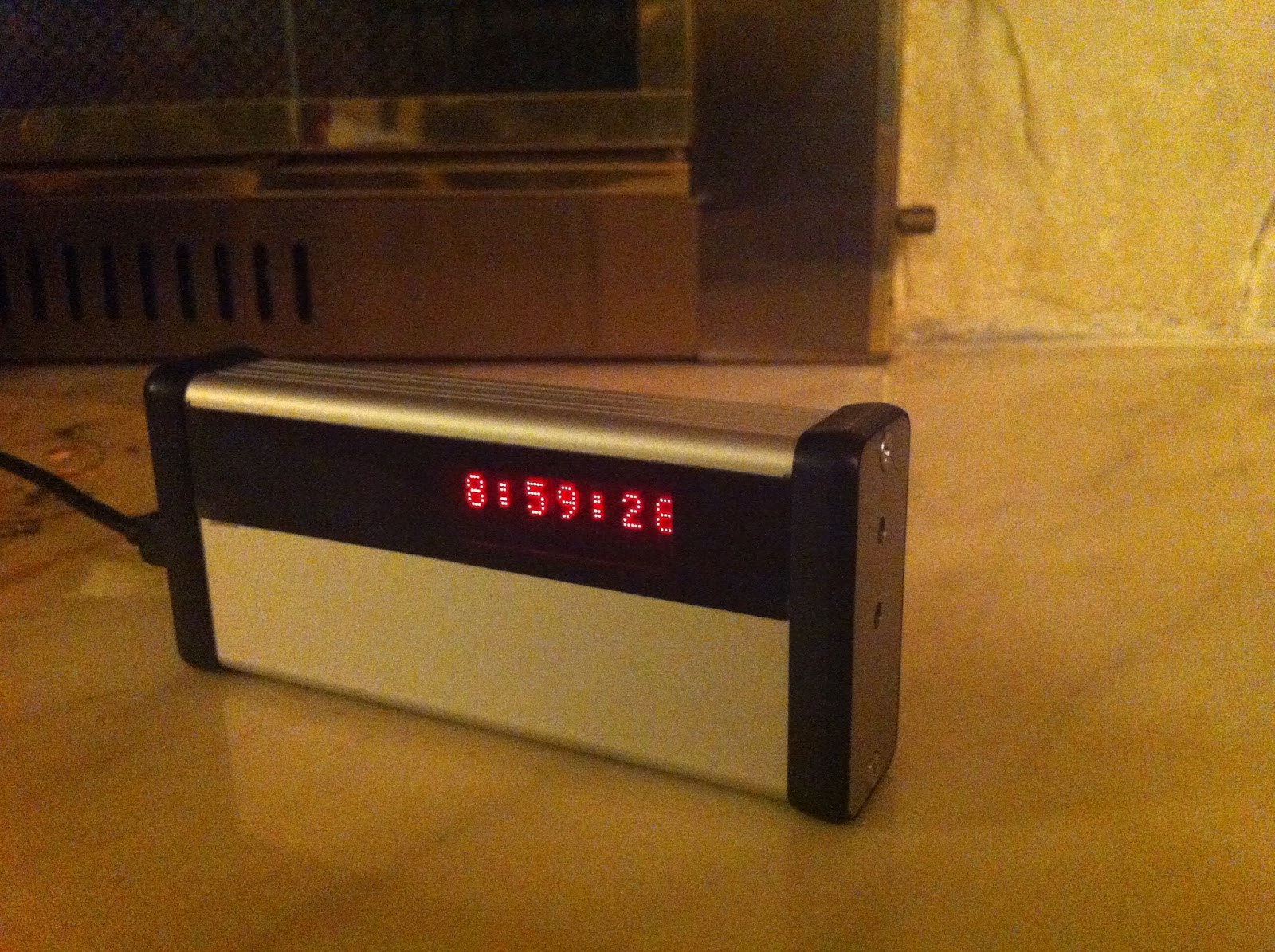
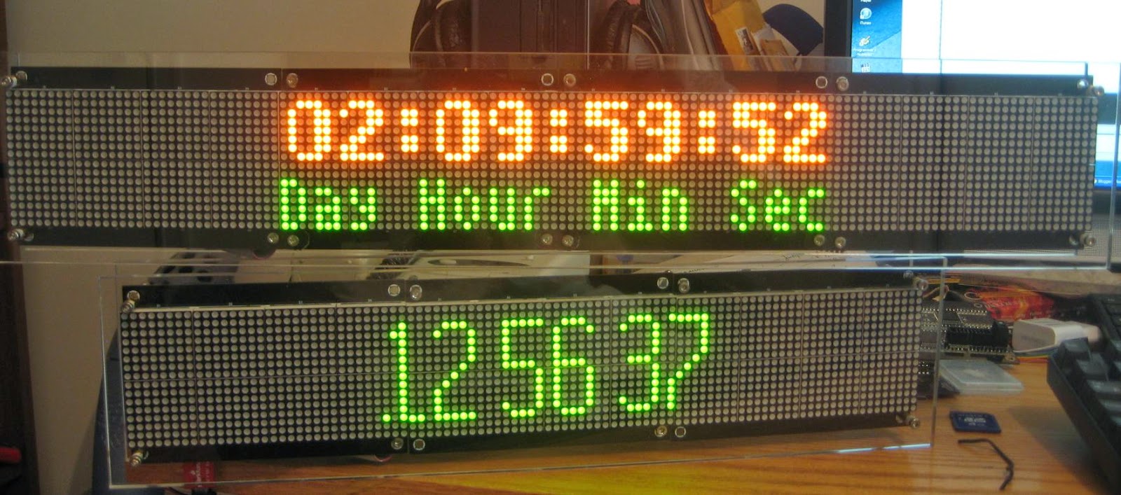
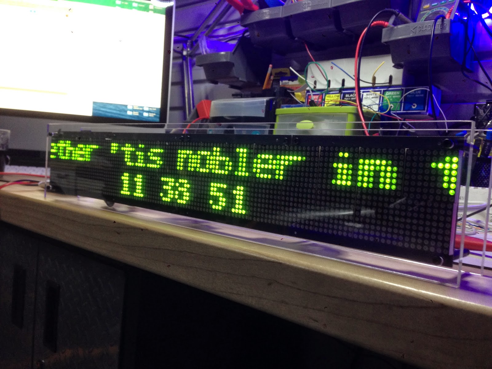
Sure 32x16 bicolor display (HT1632) driven by ESP32
I was recently awoken from the Netflix-infused lethargy by an email from LukeW, who needed help with running the Wise Clock 4 on ESP32. What a great idea that is!
I had an epiphany when I realized what a powerful platform ESP32 is: unbelievable price (about $10 on amazon), serious hardware (memory, speed, WiFi, BT, BLE, multiple USARTs etc.), amazing software support (Arduino IDE, libraries, examples etc.).
The latest Arduino IDE I had was version 1.6.7 (2017). Trying to install the support package for ESP32, I got a security error along the lines:
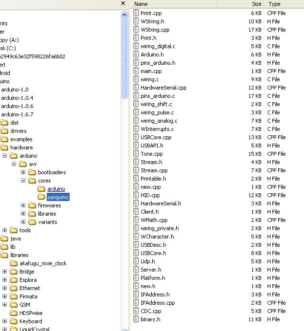
It works fine when downloading it through the browser (https://dl.espressif.com/dl/esptool-2.6.1-windows.zip), meaning that the server certificate that esspressif is using is not recognized by the JVM run by Arduino (folder "java" in the arduino directory). Identifying and adding the certificate to the JVM's keystore is time consuming, so I decided that it is just easier to upgrade to the latest Arduino IDE (currently 1.8.12), installed this time (a first for me) from Microsoft store. Even though the process is seamless, I have no idea where this software was placed (definitely not where I wanted it). I also learned the new way (where have I been for so long?) to include and manage libraries (through the "Add .ZIP library" menu item).
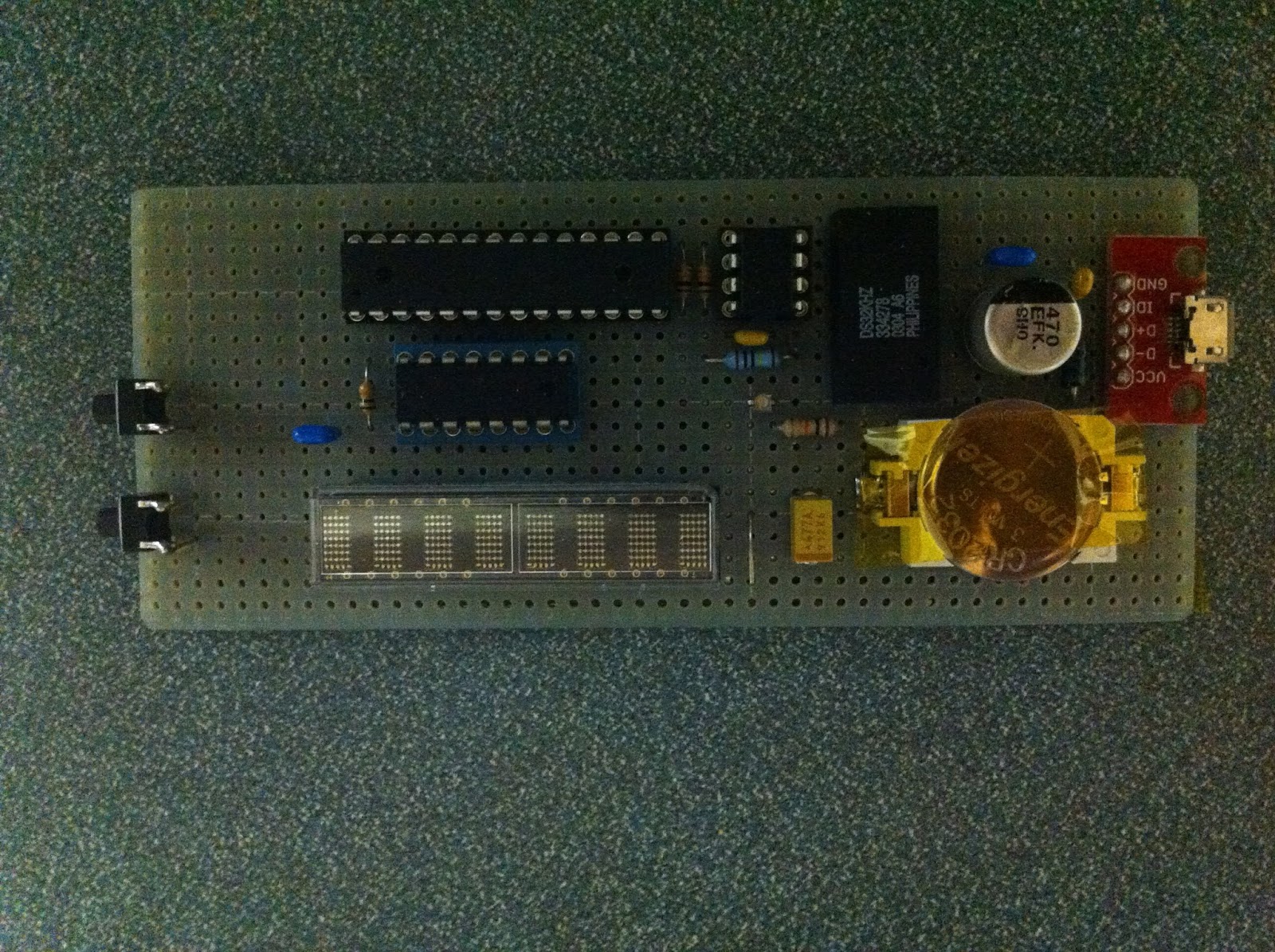
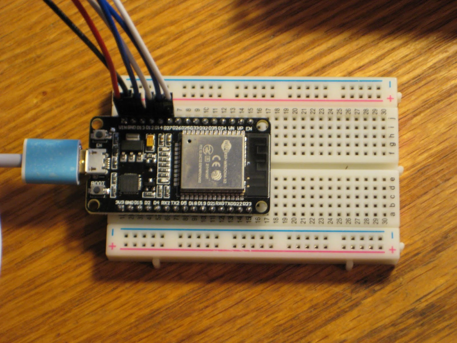
Using the ESP32 devkit is as easy as the first Arduino (Duemilanove). The only thing one needs is a solderless breadboard, which I was lucky to have one around, since I don't remember ever using one before. An interesting fact is that the ESP32 board, inserted in the breadboard I have, leaves room for connecting wires only on one side.

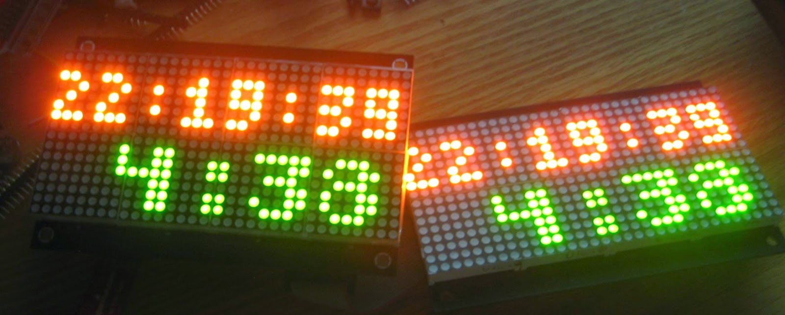
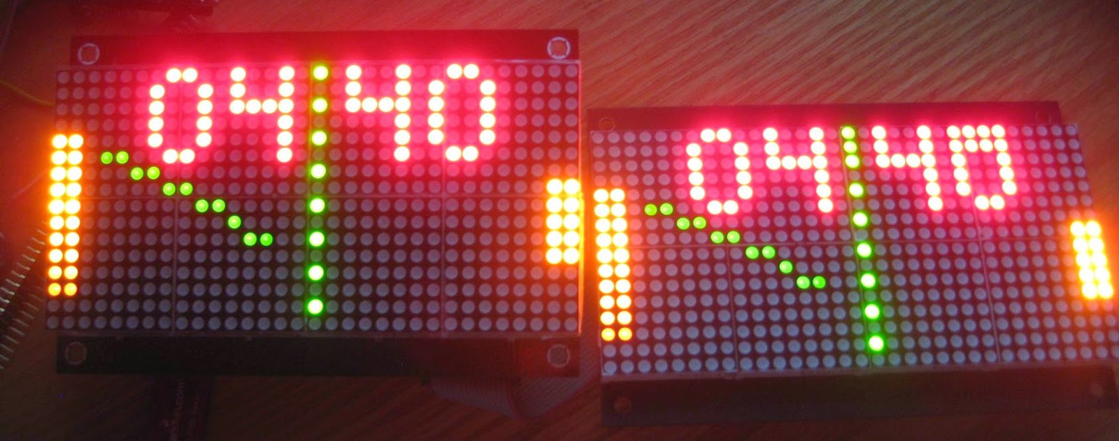
Next step was to connect the Sure 32x16 displays (two, daisy chained). I used these pins:
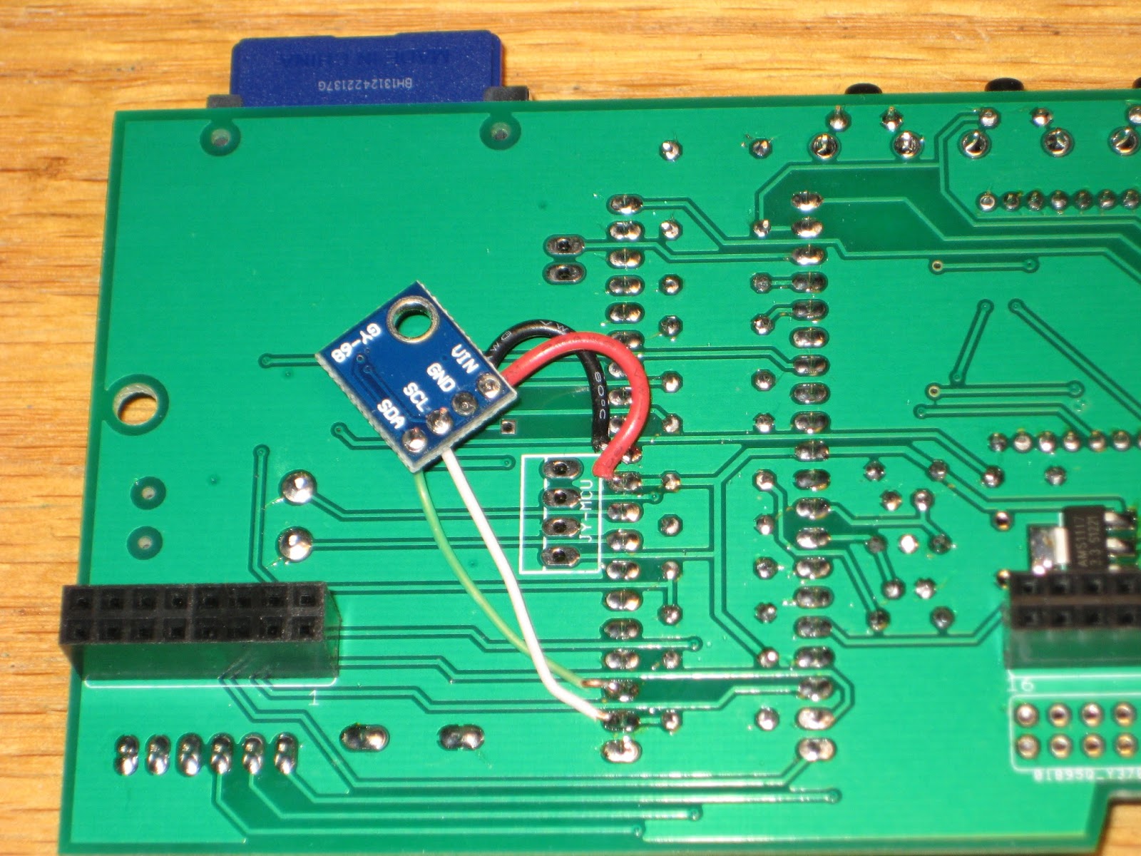
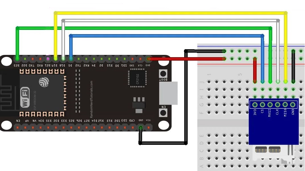
It did not take long to test the SD card, using this wiring:
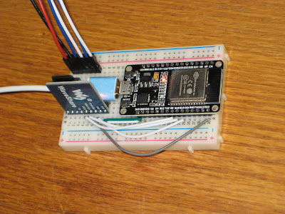
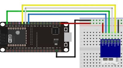 which looks like this on the breadboard:
Incredible, with no sweat at all, just out of the box. Wow again!
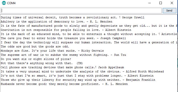
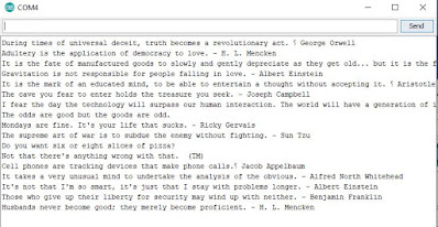
Another small step: modified the SD_Test.ino to read the content of the file, line by line:
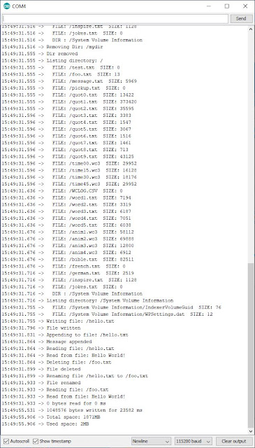
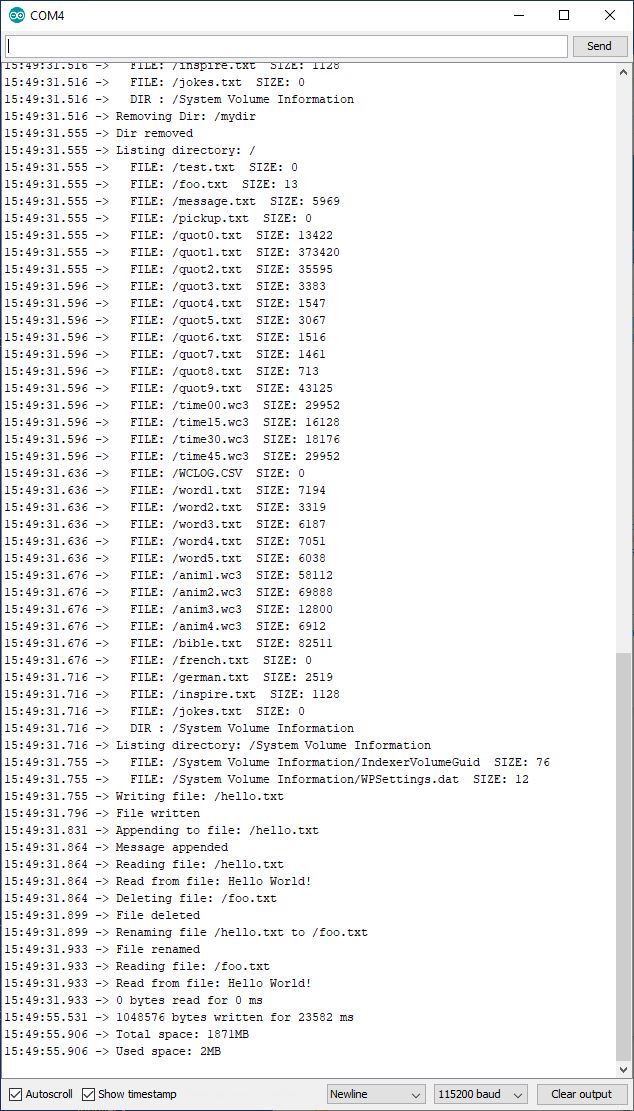
And the output, in serial monitor:
I had an epiphany when I realized what a powerful platform ESP32 is: unbelievable price (about $10 on amazon), serious hardware (memory, speed, WiFi, BT, BLE, multiple USARTs etc.), amazing software support (Arduino IDE, libraries, examples etc.).
The latest Arduino IDE I had was version 1.6.7 (2017). Trying to install the support package for ESP32, I got a security error along the lines:
javax.net.ssl.SSLHandshakeException: sun.security.validator.ValidatorException: PKIX path building failed:
sun.security.provider.certpath.SunCertPathBuilderException: unable to find valid certification path to requested target.
It works fine when downloading it through the browser (https://dl.espressif.com/dl/esptool-2.6.1-windows.zip), meaning that the server certificate that esspressif is using is not recognized by the JVM run by Arduino (folder "java" in the arduino directory). Identifying and adding the certificate to the JVM's keystore is time consuming, so I decided that it is just easier to upgrade to the latest Arduino IDE (currently 1.8.12), installed this time (a first for me) from Microsoft store. Even though the process is seamless, I have no idea where this software was placed (definitely not where I wanted it). I also learned the new way (where have I been for so long?) to include and manage libraries (through the "Add .ZIP library" menu item).
Using the ESP32 devkit is as easy as the first Arduino (Duemilanove). The only thing one needs is a solderless breadboard, which I was lucky to have one around, since I don't remember ever using one before. An interesting fact is that the ESP32 board, inserted in the breadboard I have, leaves room for connecting wires only on one side.
Next step was to connect the Sure 32x16 displays (two, daisy chained). I used these pins:
// pins used to connect to ESP32;
#define HT1632_DATA   12 // Data pin (pin 7 of display connector)
#define HT1632_CS     14 // Chip Select (pin 1 of display connector)
#define HT1632_WRCLK  13 // Write clock pin (pin 5 of display connector)
#define HT1632_CLK    27 // clock pin (pin 2 of display connector)
With only the pin changes, the HT1632 files used in Wise Clock 4 software work perfectly fine with ESP32. They can be found here, called from a test sketch that uses 2 displays (#define NUM_DISPLAYS 2 in file MyHT1632.h).
SD card should be next, using the ESP32 support libraries.
With ESP32, the sky is the limit: hopefully no more program memory limitations, no need for third party libraries (e.g. Sanguino), better support for sound, easier access to WiFi, support for extra peripherals etc. Wow!
With ESP32, the sky is the limit: hopefully no more program memory limitations, no need for third party libraries (e.g. Sanguino), better support for sound, easier access to WiFi, support for extra peripherals etc. Wow!

Running SD_Test.ino sketch example coming with ESP32 libraries on a Wise Clock 4 SD card, this is what serial monitor shows:
Another small step: modified the SD_Test.ino to read the content of the file, line by line:
void setup()
{
    Serial.begin(115200);
    if(!SD.begin()){
        Serial.println("Card Mount Failed");
        return;
    }
    uint8_t cardType = SD.cardType();

    if(cardType == CARD_NONE){
        Serial.println("No SD card attached");
        return;
    }

  openFile(SD, "/quot1.txt");
}

void openFile(fs::FS &fs, const char * path)
{
    Serial.printf("Reading file: %s\n", path);

    file = fs.open(path);
    if(!file){
        Serial.println("Failed to open file for reading");
        return;
    }
}

char lineBuf[500] = {0};

void readLine()
{
  int i = 0;
  lineBuf[0] = 0;

  while (file.available())
  {
    char c = (char) file.read();
    lineBuf[i++] = c;
    if (c == '\n')  break;
  }
  lineBuf[i] = 0;
}

void loop()
{
  readLine();
  Serial.write(lineBuf);
  delay(1000);
}