Tutorial – the Arduino AREF Pin
Learn how to measure smaller voltages with greater accuracy using your Arduino.
In this tutorial we’ll look at how you can measure smaller voltages with greater accuracy using the analogue input pins on your Arduino Uno R1 to R3 (not R4!) or compatible board in conjunction with the AREF pin. However first we’ll do some revision to get you up to speed. Please read this post entirely before working with AREF the first time.

Revision
You may recall from previous Arduino tutorials that we used the analogRead() function to measure the voltage of an electrical current from sensors and so on using one of the analogue input pins. The value returned from analogRead() would be between zero an 1023, with zero representing zero volts and 1023 representing the operating voltage of the Arduino board in use.
And when we say the operating voltage – this is the voltage available to the Arduino after the power supply circuitry. For example, if you have a typical Arduino Uno board and run it from the USB socket – sure, there is 5V available to the board from the USB socket on your computer or hub – but the voltage is reduced slightly as the current winds around the circuit to the microcontroller – or the USB source just isn’t up to scratch.
This can easily be demonstrated by connecting an Arduino Uno to USB and putting a multimeter set to measure voltage across the 5V and GND pins. Some boards will return as low as 4.8 V, some higher but still below 5V. So if you’re gunning for accuracy, power your board from an external power supply via the DC socket or Vin pin – such as 9V DC. Then after that goes through the power regulator circuit you’ll have a nice 5V, for example:

This is important as the accuracy of any analogRead() values will be affected by not having a true 5 V. If you don’t have any option, you can use some maths in your sketch to compensate for the drop in voltage. For example, if your voltage is 4.8V – the analogRead() range of 0~1023 will relate to 0~4.8V and not 0~5V. This may sound trivial, however if you’re using a sensor that returns a value as a voltage (e.g. the TMP36 temperature sensor) – the calculated value will be wrong. So in the interests of accuracy, use an external power supply.
Why does analogRead() return a value between 0 and 1023?
This is due to the resolution of the ADC. The resolution (for this article) is the degree to which something can be represented numerically. The higher the resolution, the greater accuracy with which something can be represented. We measure resolution in the terms of the number of bits of resolution.
For example, a 1-bit resolution would only allow two (two to the power of one) values – zero and one. A 2-bit resolution would allow four (two to the power of two) values – zero, one, two and three. If we tried to measure a five volt range with a two-bit resolution, and the measured voltage was four volts, our ADC would return a numerical value of 3 – as four volts falls between 3.75 and 5V. It is easier to imagine this with the following image:

So with our example ADC with 2-bit resolution, it can only represent the voltage with four possible resulting values. If the input voltage falls between 0 and 1.25, the ADC returns numerical 0; if the voltage falls between 1.25 and 2.5, the ADC returns a numerical value of 1. And so on. With our Arduino’s ADC range of 0~1023 – we have 1024 possible values – or 2 to the power of 10. So our Arduinos have an ADC with a 10-bit resolution.
So what is AREF?
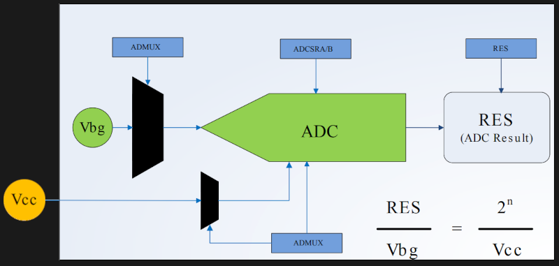
To cut a long story short, when your Arduino takes an analogue reading, it compares the voltage measured at the analogue pin being used against what is known as the reference voltage. In normal analogRead use, the reference voltage is the operating voltage of the board. For the more popular Arduino boards such as the Uno, Mega, Duemilanove and Leonardo/Yún boards, the operating voltage of 5V. If you have an Arduino Due board, the operating voltage is 3.3V. If you have something else – check the Arduino product page or ask your board supplier.
So if you have a reference voltage of 5V, each unit returned by analogRead() is valued at 0.00488 V. (This is calculated by dividing 1024 into 5V). What if we want to measure voltages between 0 and 2, or 0 and 4.6? How would the ADC know what is 100% of our voltage range?
And therein lies the reason for the AREF pin. AREF means Analogue REFerence. It allows us to feed the Arduino a reference voltage from an external power supply. For example, if we want to measure voltages with a maximum range of 3.3V, we would feed a nice smooth 3.3V into the AREF pin – perhaps from a voltage regulator IC. Then the each step of the ADC would represent around 3.22 millivolts (divide 1024 into 3.3).
Note that the lowest reference voltage you can have is 1.1V. There are two forms of AREF – internal and external, so let’s check them out.
External AREF
An external AREF is where you supply an external reference voltage to the Arduino board. This can come from a regulated power supply, or if you need 3.3V you can get it from the Arduino’s 3.3V pin. If you are using an external power supply, be sure to connect the GND to the Arduino’s GND pin. Or if you’re using the Arduno’s 3.3V source – just run a jumper from the 3.3V pin to the AREF pin.
To activate the external AREF, use the following in void setup():
analogReference(EXTERNAL); // use AREF for reference voltage
This sets the reference voltage to whatever you have connected to the AREF pin – which of course will have a voltage between 1.1V and the board’s operation voltage.
Very important note – when using an external voltage reference, you must set the analogue reference to EXTERNAL before using analogRead(). This will prevent you from shorting the active internal reference voltage and the AREF pin, which can damage the microcontroller on the board.
If necessary for your application, you can revert back to the board’s operating voltage for AREF (that is – back to normal) with the following:
analogReference(DEFAULT);
Now to demonstrate external AREF at work. Using a 3.3V AREF, the following sketch measures the voltage from A0 and displays the percentage of total AREF and the calculated voltage:
#include <LiquidCrystal.h>
LiquidCrystal lcd(8,9,4,5,6,7);

int analoginput = 0; // our analog pin
int analogamount = 0; // stores incoming value
float percentage = 0; // used to store our percentage value
float voltage =0; // used to store voltage value

void setup()
{
  lcd.begin(16, 2);
  analogReference(EXTERNAL); // use AREF for reference voltage
}

void loop()
{
  lcd.clear();
  analogamount=analogRead(analoginput);
  percentage=(analogamount/1024.00)*100;
  voltage=analogamount*3.222; // in millivolts
  lcd.setCursor(0,0);
  lcd.print("% of AREF: ");
  lcd.print(percentage,2);
  lcd.setCursor(0,1);
  lcd.print("A0 (mV): ");
  lcd.println(voltage,2);
  delay(250);
}
The results of the sketch above are shown in the following video:
Internal AREF
The microcontrollers on our Arduino boards can also generate an internal reference voltage of 1.1V and we can use this for AREF work. Simply use the line:
analogReference(INTERNAL);
For Arduino Mega boards, use:
analogReference(INTERNAL1V1);
in void setup() and you’re off. If you have an Arduino Mega there is also a 2.56V reference voltage available which is activated with:
analogReference(INTERNAL2V56);
Finally – before settling on the results from your AREF pin, always calibrate the readings against a known good multimeter.
Conclusion
The AREF function gives you more flexibility with measuring analogue signals. If you are interested in using specific ADC components, we have tutorials on the ADS1110 16-bit ADC and the NXP PCF 8591 8-bit A/D and D/A IC.
To keep up to date with new posts at tronixstuff.com, please subscribe to the mailing list in the box on the right, or follow us on X – @tronixstuff.
I hope you enjoyed making this or at least reading about it. If you find this sort of thing interesting, please consider ordering one or more of my books from amazon.
And as always, have fun and make something.