Posts with «digital audio hacks» label

How To Build Jenny’s Budget Mixing Desk

Jenny did an Ask Hackaday article earlier this month, all about the quest for a cheap computer-based audio mixer. The first attempt didn’t go so well, with a problem that many of us are familiar with: Linux applications really doesn’t like using multiple audio devices at the same time. Jenny ran into this issue, and didn’t come across a way to merge the soundcards in a single application.

I’ve fought this problem for a while, probably 10 years now. My first collision with this was an attempt to record a piano with three mics, using a couple different USB pre-amps. And of course, just like Jenny, I was quickly frustrated by the problem that my recording software would only see one interface at a time. The easy solution is to buy an interface with more channels. The Tascam US-4x4HR is a great four channel input/output audio interface, and the Behringer U-PHORIA line goes all the way up to eight mic pre-amps, expandable to 16 with a second DAC that can send audio over ADAT. But those are semi-pro interfaces, with price tags to match.

But what about Jenny’s idea, of cobbling multiple super cheap interfaces together? Well yes, that’s possible too. I’ll show you how, but first, let’s talk about how we’re going to control this software mixer monster. Yes, you can just use a mouse or keyboard, but the challenge was to build a mixing desk, and to me, that means physical faders and mute buttons. Now, there are pre-built solutions, with the Behringer X-touch being a popular solution. But again, we’re way above the price-point Jenny set for this problem. So, let’s do what we do best here at Hackaday, and build our own.

The Physical Goods

What we need is a microcontroller that has native USB client support, multiple digital I/O pins, and some analog inputs. I went with the Arduino MKRZero for the small size, decent price, and the fact that it’s actually in stock at Mouser. The other items we’ll need are some faders and buttons. I went for the full-sized 100 mm faders, and some LED toggle buttons made by Adafruit. The incidentals, like wire and resistors, was sourced from the local parts bin in the corner.

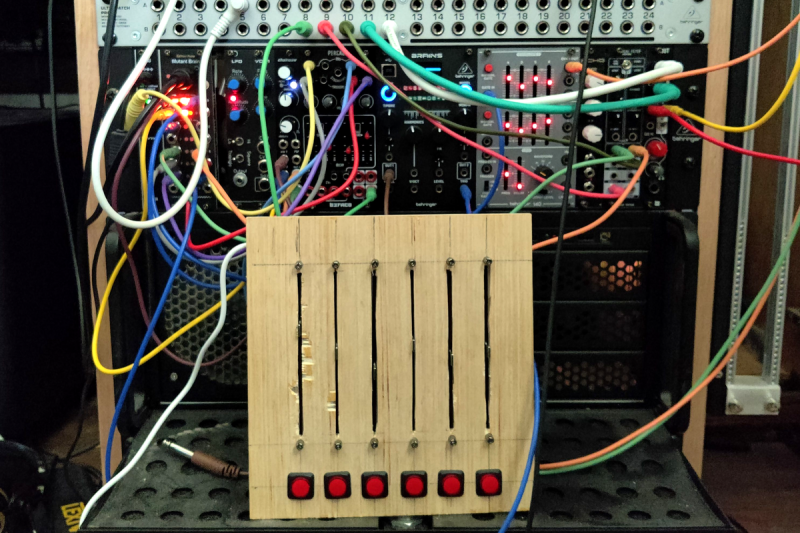
My first thought was to design and 3D print the panel, but after doing the layout on a scrap piece of plywood, the resulting size proved a bit too large for my printer. So we’re going retro, and making a “wood-grain” mixing desk. This would be a great project for a CNC router, but as I’m not part of that particular cool club yet, it was a drill press, table saw, and oscillating tool to the rescue. The results aren’t quite as pretty as I wanted, but maybe we’ll get a Mark II of this project one day.

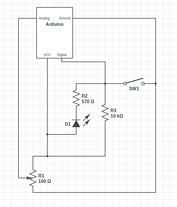
The wiring is relatively straightforward, with a current limiting resistor to protect the LEDs inside the buttons, and a pullup resistor to prevent the digital pin from floating when the button isn’t pushed. Now, that pullup might not be necessary, as I later learned that the Arduino has built-in pullup on its digital pins. And also of note, a 10 Ω resistor is *not* a good choice for a pullup. As Al eloquently put it, that’s a “pull way up resistor”. 10 kΩ is the better choice.

And to finish the build, we’ll need a sketch to run on the Arduino. Thankfully, there’s already a great library for exactly what we want to do: Control Surface. There’s a bunch of ways to set this up, but my sketch is pretty trivial:

#include <Control_Surface.h>
USBMIDI_Interface midi;

CCButtonLatching button1 {11, {MIDI_CC::General_Purpose_Controller_1, CHANNEL_1}, };
CCButtonLatching button2 {10, {MIDI_CC::General_Purpose_Controller_2, CHANNEL_1}, };
CCButtonLatching button3 {9, {MIDI_CC::General_Purpose_Controller_3, CHANNEL_1}, };
CCButtonLatching button4 {8, {MIDI_CC::General_Purpose_Controller_4, CHANNEL_1}, };
CCButtonLatching button5 {7, {MIDI_CC::General_Purpose_Controller_5, CHANNEL_1}, };
CCButtonLatching button6 {6, {MIDI_CC::General_Purpose_Controller_6, CHANNEL_1}, };
  
CCPotentiometer volumePotentiometers[] {
  {A0, {MIDI_CC::Sound_Controller_1, CHANNEL_1} },
  {A1, {MIDI_CC::Sound_Controller_2, CHANNEL_1} },
  {A2, {MIDI_CC::Sound_Controller_3, CHANNEL_1} },
  {A3, {MIDI_CC::Sound_Controller_4, CHANNEL_1} },
  {A4, {MIDI_CC::Sound_Controller_5, CHANNEL_1} },
  {A5, {MIDI_CC::Sound_Controller_6, CHANNEL_1} },
};
void setup() {
    Control_Surface.begin();
}
void loop() {
    Control_Surface.loop();
}

Pipewire to the Rescue

And now on to the meat and potatoes of this project. How do we convince an application to see inputs from multiple devices, and actually do some mixing? The problem here is de-sync. Each device runs on a different clock source, and so the bitstream from each may wander and go out of sync. That’s a serious enough problem that older sound solutions didn’t implement much in the way of card combining. Not long ago, the process of resampling those audio streams to get them to properly sync would have been a very CPU intensive procedure. But these days we all have multi-core behemoths, practical super-computers compared to 20 years ago.

So when Wim Taymans wrote Pipewire, he took a different approach. We have enough cycles to resample, so Pipewire will transparently do so when needed. Pipewire sees all your audio interfaces at once, and implements both the Jack and Pulseaudio APIs. Different distros handle this a bit differently, but generally you need the Pipewire packages, as well as the pipewire-jack and pipewire-pulseaudio packages to get that working.

And here’s the secret: The Jack routing tools work with Pipewire. The big three options are qjackctl, carla, and qpwgraph, though note that qpwgraph is actually Pipewire native. So even if an application can only select a single device at a time, if that app uses the Jack, Pulseaudio, or Pipewire API, you can use one of those routing control programs to arbitrary connect inputs and outputs.

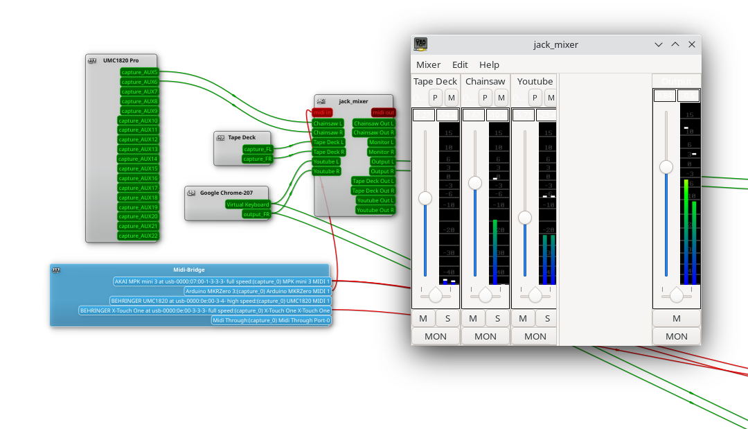
So let’s start with the simplest solution: jack_mixer. Launch the application, and then using your preferred routing controllers, take the MIDI output from our Arduino control surface, and connect it into jack_mixer‘s MIDI input. In jack_mixer, add a new input channel, and give it an appropriate name. Let’s call it “tape deck”, since I have a USB tape deck I’m testing this with. Now the controller magic kicks in: hit the “learn” button for the volume control, and wiggle the first fader on that controller. Then follow with the mute button, and save the new channel. We’ll want to add an output channel, too. Feel free to assign one of your faders to this one, too.

And finally, back to the routing program, and connect your tape deck’s output to jack_mixer input, and route jack_mixer‘s output to your speakers. Play a tape, and enjoy the full control you have over volume and muting! Want to add a Youtube video to the mix? Start the video playing, and just use the routing controller to disconnect it from your speakers, and feed it into a second channel on jack_mixer. Repeat with each of those five cheap and nasty sound cards. Profit!

You Want More?

There’s one more application to mention here. Instead of using jack_mixer, we can use Ardour to do the heavy lifting. To set it up this way, there are two primary Ardour settings, found under preferences: Under the monitoring tab make sure “Record monitoring handled by” is set to Ardour, and the “auto Input does talkback” option is checked. Then add your tracks, set the track input to the appropriate input hardware, and the track output to the master bus. Make sure the master bus is routed to where you want it, and you should be able to live mix with Ardour, too.

This gives you all sorts of goodies to play with, in the form of plugins. Want a compressor or EQ on a sound source? No problem. Want to autotune a source? X42 has a plugin that does that. And of course, Ardour brings recording, looping, and all sorts of other options to the party.

Ardour supports our custom mixing interface, too. Also under preferences, look for the Control Surfaces tab, and make sure General MIDI is checked. Then highlight that and click the “Show Protocol Settings” button. Incoming MIDI should be set to our Arduino device. You can then use the Ctrl + Middle Click shortcut on the channel faders and mute buttons, to put them in learn mode. Wiggle a control to assign it to that task. Or alternatively you can add a .map file to Ardour’s midi_maps directory. Mine looks like this:

 
  <?xml version="1.0" encoding="UTF-8"?>
<ArdourMIDIBindings version="1.1.0" name="Arduino Mapping">
  <Binding channel="1" ctl="16" uri="/route/mute B1"/>
  <Binding channel="1" ctl="70" uri="/route/gain B1"/>
  <Binding channel="1" ctl="17" uri="/route/mute B2"/>
  <Binding channel="1" ctl="71" uri="/route/gain B2"/>
  <Binding channel="1" ctl="18" uri="/route/mute B3"/>
  <Binding channel="1" ctl="72" uri="/route/gain B3"/>
  <Binding channel="1" ctl="19" uri="/route/mute B4"/>
  <Binding channel="1" ctl="73" uri="/route/gain B4"/>
  <Binding channel="1" ctl="80" uri="/route/mute B5"/>
  <Binding channel="1" ctl="74" uri="/route/gain B5"/>
  <Binding channel="1" ctl="81" uri="/route/mute B6"/>
  <Binding channel="1" ctl="75" uri="/route/gain B6"/>
</ArdourMIDIBindings>

The Caveats

Now before you get too excited, and go sink a bunch of money and/or time into a Linux audio setup, there are some things you should know. First is latency. It’s really challenging to get a Pipewire system set up to achieve really low latency, particularly when you’re using USB-based hardware. It’s possible, and work is ongoing on the topic. But so far the best I’ve managed to run stable is a 22 millisecond round-trip measurement — and that took a lot of fiddling with the Pipewire config files to avoid garbled audio. That’s just about usable for self monitoring and live music, and for playing anything pre-recorded, that’s perfectly fine.

The second thing to know is that this was awesome. It’s a bit concerning how much fun it is to combine some decent audio hardware with the amazing free tools that are available. Want to auto-tune your voice for your next Zoom meeting? Easy. Build a tiny MIDI keyboard into your desk? Just a microcontroller and some soldering away. The sky’s the limit. And the future is bright, too. Tools like Pipewire and Ardour are under very active development, and the realtime kernel patches are just about to make it over the finish line. Go nuts, create cool stuff, and then be sure to tell us about it!

An Arduino And A CD-ROM Drive Makes A CD Player

In an age of streaming media it’s easy to forget the audio CD, but they still remain as a physical format from the days when the “Play” button was not yet the “Pay” button. A CD player may no longer be the prized possession it once was, but it’s still possible to dabble in the world of 120 mm polycarbonate discs if you have a fancy for it. It’s something [Daniel1111] has done with his Arduino CD player, which uses the little microcontroller board to control a CD-ROM drive via its IDE bus.

The project draws heavily from the work of previous experimenters, notably ATAPIDUINO, but it extends them by taking its audio from the drive’s S/PDIF output. A port expander drives the IDE interface, while a Cirrus Logic WM8805 S/PDIF transceiver handles the digital audio and converts it to an I2S stream. That in turn is fed to a Texas Instruments PCM5102 DAC, which provides a line-level audio output. All the code and schematic can be found in a GitHub repository.

To anyone who worked in the CD-ROM business back in the 1990s this project presses quite a few buttons, though perhaps not enough to dig out all those CDs again. It would be interesting to see whether the I2S stream could be lifted from inside the drive directly, or even if the audio data could be received via the IDE bus. If you’d like to know a bit more about I2S , we have an article for you.

Hack a Day 03 Jan 12:00

How To Hack A Portable Bluetooth Speaker By Skipping The Bluetooth

Portable Bluetooth speakers have joined the club of ubiquitous personal electronics. What was once an expensive luxury is now widely accessible thanks to a prolific landscape of manufacturers mass producing speakers to fit every taste and budget. Some have even become branded promotional giveaway items. As a consequence, nowadays it’s not unusual to have a small collection of them, a fertile field for hacking.

But many surplus speakers are put on a shelf for “do something with it later” only to collect dust. Our main obstacle is a side effect of market diversity: with so many different speakers, a hack posted for one speaker wouldn’t apply to another. Some speakers are amenable to custom firmware, but only a small minority have attracted a software development community. It doesn’t help that most Bluetooth audio modules are opaque, their development toolchains difficult to obtain.

So what if we just take advantage of the best parts of these speakers: great audio fidelity, portability, and the polished look of a consumer good, to serves as the host for our own audio-based hacks. Let’s throw the Bluetooth overboard but embrace all those other things. Now hacking these boxes just requires a change of mindset and a little detective work. I’ll show you how to drop an Arduino into a cheap speaker as the blueprint for your own audio adventures.

Directing the Hacker Mindset at Myriad Bluetooth Speakers

There’s way too many different speakers out there for one hack to rule them all. But by changing our Bluetooth speaker mindset from “it’s a reprogrammable computer” to “it’s an integrated collection of useful electronic components”, we turn market diversity into our ally.

Look at this from the perspective of Bluetooth speaker manufacturers: they want their Bluetooth speaker to stand out from competitors, and the most obvious way is in their selection of loudspeaker drivers. Surprising the customer with big sound from a little box is key for success, so each product can offer a unique combination for driving the audio, all housed inside an eye-catching enclosure that lets consumers tell one portable Bluetooth speaker from another.

Tailoring for loudspeaker selection has cascading effects through the rest of the system. For best sound, they will need matching audio amplifier modules, which will have their own power requirements, which dictates battery performance, and so on. Catering to these desires, components are excluded from the tightly integrated mystery black boxes. Fortunately for hardware hackers, such an architecture also makes components easy to reuse:

  1. A rechargeable battery.
  2. Ability to charge that battery from USB.
  3. A low-power standby mode to monitor press of the power button.
  4. Protecting battery from over-discharge.
  5. A voltage regulator supplying battery power to the device.
  6. An audio line-in jack.
  7. Volume up/down control.
  8. Amplifier and driver.

All of these are useful for projects, already neatly packaged in a mass-produced enclosure.

Putting Theory Into Practice With An Example

Now that we have a general background, let’s apply this concept to a specific example. But before we begin, an obligatory note in case it is not obvious to any beginners reading this: This activity very definitely voids the warranty (do it, it’s worth it!), and modern portable electronics use lithium chemistry batteries that can be dangerous if mistreated.

The Bluetooth speaker used in this example is a “Rugged Portable Bluetooth Speaker” sold by North American electronics retailer Best Buy under one of their house brands. A search of its FCC ID pointed to Lightcomm Technology Co. as the manufacturer. The “rugged” claim starts with a layer of soft rubber wrapped around its exterior. That plus reinforcements inside the case allows the speaker to absorb some level of abuse. I wanted to preserve this shock absorbing exterior and, thankfully, it was easy to open non-destructively. Even more care would be needed if it was a waterproof speaker (this one wasn’t) and moisture barriers need to be preserved. Alternatively, if the plan is to transfer the internals to another enclosure, the condition of the original box would not matter.

Once the circuit board has been extracted, the Bluetooth interface module should immediately stand out as the most sophisticated component sitting close to an antenna. A search for ATS2823 confirmed it is a module designed and sold for integration into Bluetooth audio products. Its MIPS M4K core and associated flash storage could be a promising start for firmware hacking, but the point of this example is to demonstrate how to hack a speaker utilizing existing firmware. So we will leave the module as-is.

Solder to the External Audio Input

The easiest way to pipe audio into this system is to pretend to be an external audio source. We want the system to believe we are connected via an audio cable plugged into the line-in jack, but for compactness we’d prefer to do this without using an actual cord. This approach is easy, nondestructive, and preserves the existing volume control mechanism. There are a lot of different ways to implement an audio jack, so some exploration with a multimeter will be required. We need to find the standardized contacts for: audio input left channel, right channel, and ground. (Wikipedia reference: “Phone connector (audio)“)

It’ll be a little tricker to decipher the plug detection scheme, as it is not standardized. In this particular example, there is a fourth pin that floats in the absence of an audio plug. When an audio plug is present, the pin is grounded. Soldering a wire to always ground that detection pin will keep this speaker constantly in “playing external audio” mode.

Or Connect To Amplifier Directly

An alternative approach is to bypass existing input and volume control, sending audio directly to the amplifier chip. To find this chip, we start with the voice coil wires and backtrack. It’ll likely be the largest component near those voice coil wires. Once the amplifier chip is found, consult the datasheet to find the input pins to cut free from the circuit and rewire for audio input that bypasses existing control.

But even if we wish to maintain existing volume control, it is still useful to locate the audio amplifier chip. It is the most power-hungry component on the circuit board, and peak power requirements for the system are dictated by the amount of power this amplifier will draw when playing loudly. Therefore it is half the puzzle of calculating our available power. This particular Bluetooth device uses a Mixinno MIX2052 chip sitting adjacent to the voice coil wire connector, with a peak power of 6 watts.

Tap Into Power Supply

The other half of the puzzle is the voltage regulator delivering power to the amplifier chip. Similar to how we look for our amplifier near our voice coil wires, we can look for our regulator sitting near inductors, capacitors, and diodes. Once the power module is found, read its data sheet to determine peak power output.

The power budget for our hack would be constrained by power figures for those two components. Most microcontrollers consume maximum power during bootup. So as long as the audio source stays quiet during this time, we would have a little extra power to support boot. Somewhere between the regulator and the amplifier is also the best place to tap power. It allows us to piggyback on the existing power management circuit that shuts down the amplifier when entering low power mode, cutting power to our hack at the same time.

In the case of this board, there was one prominent coil and a Techcode TD8208 step-up regulator was found next to it. Configured to deliver 5 volts, this regulator can deliver 1A and tolerate brief spikes not to exceed 2A. This wouldn’t be enough to feed a Raspberry Pi 4, but plenty for an Arduino Nano.

Repurpose Control Button

So far functionality for three of the four buttons on this speaker has been preserved: power, volume up, and volume down. The fourth button initiates Bluetooth pairing, or to pick up a phone call. We’re cutting BT out of the equation so this is no longer useful and can be repurposed.

On this speaker, SW4 is normally open and pulls to ground when pressed, making it trivial to reuse. I cut the trace leading to the Bluetooth interface module and soldered a wire so the switch now pulls an Arduino pin to ground when pressed.

Tuck Everything Back In

A few pieces of internal plastic reinforcements for ruggedness were cut away to create enough volume for an Arduino Nano inside this enclosure. It is no longer quite as rugged, but now it is far more interesting as a platform for sound hacks. To conclude this proof of concept, the Arduino Nano is using the Mozzi audio library to play the classic Wilhelm scream whenever our repurposed button is pressed.


Build Your Own Bleepy Bloopy Buzzy Box

Bluetooth used to be the novelty. With plenty of hacks adding Bluetooth to existing audio equipment, playing Bluetooth audio out of one, or building our own Bluetooth speakers from scratch. But now Bluetooth speakers are ubiquitous, we’re approaching the point where Bluetooth is not necessarily the center of attention. Skipping the Bluetooth in a portable Bluetooth speaker gives us a new platform for our noise maker hacks. Something small, fun, and easy to bring to our next hacker show-and-tell meetup!

Stomping On Microcontrollers: Arduino Mega Guitar Effects Pedal

Effects pedals: for some an object of overwhelming addiction, but for many, an opportunity to hack. Anyone who plays guitar (or buys presents for someone who does) knows of the infinite choice of pedals available. There are so many pedals because nailing the tone you hear in your head is an addictive quest, an itch that must be scratched. Rising to meet this challenge are a generation of programmable pedals that can tweak effects in clever ways.

With this in mind, [ElectroSmash] are back at it with another open source offering: the pedalSHIELD MEGA. Aimed at musicians and hackers who want to learn more about audio, DSP and programming, this is an open-hardware/open-software shield for the Arduino MEGA which transforms it into an effects pedal.

The hardware consists of an analog input stage which amplifies and filters the incoming signal before passing it to the Arduino, as well as an output stage which does the DAC-ing from the Arduino’s PWM outputs, and some more filtering/amplifying. Two 8-bit PWM outputs are used simultaneously to make pseudo 16-bit resolution — a technique you can read more about in their handy forum guide.

The list of effects currently implemented covers all the basics you’d expect, and provides a good starting point for writing custom effects. Perhaps a library for some of the commonly used config/operations would be useful? Naturally, there are some computational constraints when using an Arduino for DSP, though it’s up to you whether this is a frustrating fact, or an opportunity to write some nicely optimised code.

[ElectroSmash] don’t just do pedals either: here’s their open source guitar amp.

Keytar Made Out Of A Scanner To Make Even the 80s Jealous

Do any of you stay awake at night agonizing over how the keytar could get even cooler? The 80s are over, so we know none of us do. Yet here we are, [James Cochrane] has gone out and turned a HP ScanJet Keytar for no apparent reason other than he thought it’d be cool. Don’t bring the 80’s back [James], the world is still recovering from the last time.

Kidding aside (except for the part of not bringing the 80s back), the keytar build is simple, but pretty cool. [James] took an Arduino, a MIDI interface, and a stepper motor driver and integrated it into some of the scanner’s original features. The travel that used to run the optics back and forth now produce the sound; the case of the scanner provides the resonance. He uses a sensor to detect when he’s at the end of the scanner’s travel and it instantly reverses to avoid collision.

A off-the-shelf MIDI keyboard acts as the input for the instrument. As you can hear in the video after the break; it’s not the worst sounding instrument in this age of digital music. As a bonus, he has an additional tutorial on making any stepper motor a MIDI device at the end of the video.

If you don’t have an HP ScanJet lying around, but you are up to your ears in surplus Commodore 64s, we’ve got another build you should check out.


Filed under: Arduino Hacks, digital audio hacks, musical hacks

Hackaday Prize Entry: 8-Bit Arduino Audio for Squares

A stock Arduino isn’t really known for its hi-fi audio generating abilities. For “serious” audio like sample playback, people usually add a shield with hardware to do the heavy lifting. Short of that, many projects limit themselves to constant-volume square waves, which is musically uninspiring, but it’s easy.

[Connor]’s volume-control scheme for the Arduino bridges the gap. He starts off with the tone library that makes those boring square waves, and adds dynamic volume control. The difference is easy to hear: in nature almost no sounds start and end instantaneously. Hit a gong and it rings, all the while getting quieter. That’s what [Connor]’s code lets you do with your Arduino and very little extra work on your part.

The code that accompanies the demo video (which is embedded below) is a good place to start playing around. The Gameboy/Mario sound, for instance, is as simple as playing two tones, and making the second one fade out. Nonetheless, it sounds great.

Behind the scenes, it uses Timer 0 at maximum speed to create the “analog” values (via PWM and the analogWrite() command) and Timer 1 to create the audio-rate square waves. That’s it, really, but that’s enough. A lot of beloved classic arcade games didn’t do much more.

While you can do significantly fancier things (like sample playback) with the same hardware, the volume-envelope-square-wave approach is easy to write code for. And if all you want is some simple, robotic-sounding sound effects for your robot, we really like this approach.

The HackadayPrize2016 is Sponsored by:

Filed under: Arduino Hacks, digital audio hacks, The Hackaday Prize

Embed with Elliot: Audio Playback with Direct Digital Synthesis

Direct-digital synthesis (DDS) is a sample-playback technique that is useful for adding a little bit of audio to your projects without additional hardware. Want your robot to say ouch when it bumps into a wall? Or to play a flute solo? Of course, you could just buy a cheap WAV playback shield or module and write all of the samples to an SD card. Then you wouldn’t have to know anything about how microcontrollers can produce pitched audio, and could just skip the rest of this column and get on with your life.

~45db signal to noise ratio from an Arduino

But that’s not the way we roll. We’re going to embed the audio data in the code, and play it back with absolutely minimal additional hardware. And we’ll also gain control of the process. If you want to play your samples faster or slower, or add a tremolo effect, you’re going to want to take things into your own hands. We’re going to show you how to take a single sample of data and play it back at any pitch you’d like. DDS, oversimplified, is a way to make these modifications in pitch possible even though you’re using a fixed-frequency clock.

The same techniques used here can turn your microcontroller into a cheap and cheerful function generator that’s good for under a hundred kilohertz using PWM, and much faster with a better analog output. Hackaday’s own [Bil Herd] has a nice video post about the hardware side of digital signal generation that makes a great companion to this one if you’d like to go that route. But we’ll be focusing here on audio, because it’s easier, hands-on, and fun.

We’ll start out with a sample of the audio that you’d like to play back — that is some data that corresponds to the voltage level measured by a microphone or something similar at regular points in time. To play the sample, all we’ll need to do is have the microcontroller output these voltages back at exactly the same speed. Let’s say that your “analog” output is via PWM, but it could easily be any other digital-to-analog converter (DAC) of your choosing. Each sample period, your code looks up a value and writes it out to the DAC. Done!

(In fact, other than reading the data from an SD card’s filesystem, and maybe having some on-board amplification, that’s about all those little WAV-player units are doing.)

Pitch Control

In the simplest example, the sample will play back at exactly the same pitch it was recorded if the sample playback rate equals the input sampling rate. You can make the pitch sound higher by playing back faster, and vice-versa. The obvious way to do this is to change the sample-playback clock. Every period you play back one the next sample, but you change the time between samples to give you the desired pitch. This works great for one sample, and if you have infinitely variable playback rates available.

Woof!

But let’s say that you want to take that sample of your dog barking and play Beethoven’s Fifth with it. You’re going to need multiple voices playing the sample back at different speeds to make the different pitches. Playing multiple pitches in this simplistic way, would require multiple sample-playback clocks.

Here’s where DDS comes in. The idea is that, given a sampled waveform, you can play nearly any frequency from a fixed clock by skipping or repeating points of the sample as necessary. Doing this efficiently, and with minimal added distortion, is the trick to DDS. DDS has its limits, but they’re mostly due to the processor you’re using. You can buy radio-frequency DDS chips these days that output very clean sampled sine waves up to hundreds of megahertz with amazing frequency stability, so you know the method is sound.

Example

Let’s make things concrete with a simplistic example. Say we have a sample of a single cycle of a waveform that’s 256 bytes long, and each 8-bit byte corresponds to a single measured voltage at a point in time. If we play this sample back at ten microseconds per sample we’ll get a pitch of 1 / (10e-06 * 256) = 390.625 Hz, around the “G” in the middle of a piano.

Imagine that our playback clock can’t go any faster, but we’d nonetheless like to play the “A” that’s just a little bit higher in pitch, at 440 Hz. We’d be able to play the “A” if we had only sampled 227 bytes of data in the first place: 1 / (10e-06 * 227) = 440.53, but it’s a little bit late to be thinking of that now. On the other hand, if we just ignored 29 of the samples, we’d be there. The same logic works for playing lower notes, but in reverse. If some samples were played twice, or even more times, you could slow down the repetition rate of the cycle arbitrarily.

In the skipping-samples case, you could just chop off the last 29 samples, but that would pretty seriously distort your waveform. You could imagine spreading the 29 samples throughout the 256 and deleting them that way, and that would work better. DDS takes this one step further by removing different, evenly spaced samples with each cycle through the sampled waveform. And it does it all through some simple math.

The crux is the accumulator. We’ll embed the 256 samples in a larger space — that is we’ll create a new counter with many more steps so that each step in our sample corresponds to many numbers in our larger counter, the accumulator. In my example code below, each of the 256 steps gets 256 counts. So to advance one sample per period, we need to add 256 to the larger counter. To go faster, you add more than 256 each period, and to go slower, add less. That’s all there is to it, except for implementation details.

In the graph here, because I can’t draw 1,024 tick marks, we have 72 steps in the accumulator (the green outer ring) and twelve samples (inner, blue). Each sample corresponds to six steps in the accumulator. We’re advancing the accumulator four steps per period (the red lines) and you can see how the first sample gets played twice, then the next sample played only once, etc. In the end, the sample is played slower than if you took one sample per time period. If you take more than six steps in the increment, some samples will get skipped, and the waveform will play faster.

Implementation and Build

So let’s code this up and flash it into an Arduino for testing. The code is up at GitHub for you to follow along. We’ll go through three demos: a basic implementation that works, a refined version that works a little better, and finally a goofy version that plays back single samples of dogs barking.

Filter “circuit”

In overview, we’ll be producing the analog output waveforms using filtered PWM, and using the hardware-level PWM control in the AVR chip to do it. Briefly, there’s a timer that counts from 0 to 255 repeatedly, and turns on a pin at the start and turns it off at a specified top value along the way. This lets us create a fast PWM signal with minimal CPU overhead, and it uses a timer.

Still some jaggies left. Could use better filter.

We’ll use another timer that fires off periodically and runs some code, called an interrupt service routine (ISR), that loads the current sample into the PWM register. All of our DDS code will live in this ISR, so that’s all we’ll focus on.

If this is your first time working directly with the timer/counters on a microcontroller, you’ll find some configuration code that you don’t really have to worry about. All you need to know is that it sets up two timers: one running as fast as possible and controlling a PWM pin for audio output, and another running so that a particular chunk of code is called consistently, 24,000 times per second in this example.

So without further ado, here’s the ISR:

struct DDS {
    uint16_t increment;
    uint16_t position;
    uint16_t accumulator;
    const int8_t* sample;   /* pointer to beginning of sample in memory */
};
volatile struct DDS voices[NUM_VOICES];

ISR(TIMER1_COMPA_vect) {
    int16_t total = 0;

    for (uint8_t i = 0; i < NUM_VOICES; i++) {
        total += (int8_t) pgm_read_byte_near(voices[i].sample + voices[i].position);

        /* Take an increment step */
        voices[i].accumulator += voices[i].increment;
        voices[i].position += voices[i].accumulator / ACCUMULATOR_STEPS;
        voices[i].accumulator = voices[i].accumulator % ACCUMULATOR_STEPS;
        voices[i].position = voices[i].position % SAMPLE_LENGTH;
    }

    total = total / NUM_VOICES;
    OCR2A = total + 128; // add in offset to make it 0-255 rather than -128 to 127
}

The first thing the code does is to define a (global) variable that will hold the state of each voice for as many voices as we want, defined by NUM_VOICES. Each voice has an increment which determines how many steps to take in the accumulator per sample output. The position keeps track of exactly which of the 256 samples in our waveform data is currently playing, and the accumulator keeps track of the rest. Here, we’re also allowing for each voice to play back a different waveform table from memory, so the code needs to keep track of the address where each sample begins. Changing which sample gets played back is as simple as pointing this variable to a different memory location, as we’ll see later. For concreteness, you can imagine this sample memory to contain the points in a sine wave, but in practice any repetitive waveform will do.

So let’s dive into the ISR, and the meat of the routine. Each update cycle, the sum of the output on the different voices is calculated in total. For each voice, the current sample is read from memory, added to the total and then incremented to the next step. Here we get to see how the accumulator works. The increment variable is added to the accumulator. When the accumulator is larger than the number of steps per sample, the position variable gets moved along. Next, the accumulator is shrunk back down to just the remainder of the un-accounted-for values using the modulo operator, and the sample position is wrapped around if necessary with another modulo.

Division?? Modulo??

If you’ve worked with microcontrollers before, alarm bells may be going off in your head right now. The AVR doesn’t have a built-in division routine, so that could take a lot of CPU power. And the modulo operator is even worse. That is, unless the divisor or modulo are powers of two. In those cases, the division is the same as shifting the binary number to the right by the number of bits in the power of two.

A similar operation makes the modulo tolerable. If, for instance, you want a number to be modulo eight, you can simply drop all of the binary bits that correspond to values eight and higher. So, x % 8 can be implemented as x & 0b00000111 where this logical-ANDing just keeps the least-significant three bits. If you’re not in tune with your inner bit-flipper, this can be viewed as a detail — but just know that division and modulo aren’t necessarily bad news if your compiler knows how to implement them efficiently when you choose powers of two for the divisors.

And that gets us to the end of the routine. The sample values were added together, so now they need dividing by the number of voices and centering around the mid-point to fit inside the 8-bit range that the PWM output register requires. As soon as this value is loaded into memory, the PWM hardware will take care of outputting the right waveform on its next cycle.

Refinements

The ISR above is already fairly streamlined. It’s avoided the use of any if statements that would otherwise slow it down. But it turns out we can do better, and this optimized form is often the way you’ll see DDS presented. Remember, we’re running this ISR (in this example) 24,000 times per second — any speedup inside the ISR makes a big difference in overall CPU usage.

The first thing we’ll do is make sure that we have only 256 samples. That way, we can get rid of the line where we limit the sample index to being within the correct range simply by using an 8-bit variable for the sample value. As long as the number of bits in the sample index matches the length of the sample, it will roll over automatically.

We can use the same logic to merge the sample and accumulator variables above into a single variable. If we have an 8-bit sample and an 8-bit accumulator, we combine them into a 16-bit accumulator where the top eight bits correspond to the sample location.

struct DDS {
    uint16_t increment;
    uint16_t accumulator;
    const int8_t* sample;   /* pointer to beginning of sample in memory */
};
volatile struct DDS voices[NUM_VOICES];

ISR(TIMER1_COMPA_vect) {
    int16_t total = 0;

    for (uint8_t i = 0; i < NUM_VOICES; i++) { total += (int8_t) pgm_read_byte_near(voices[i].sample + (voices[i].accumulator >> 8));
        voices[i].accumulator += voices[i].increment;
    }
    total = total / NUM_VOICES;
    OCR2A = total + 128; // add in offset to make it 0-255 rather than -128 to 127
}

You can see that we’ve dropped the position value from the DDS structure entirely, and that the ISR is significantly streamlined in terms of lines of code. (It actually runs about 10% faster too.) Where previously we played the sample at sample + position, we are now playing the sample at sample + (accumulator >> 8). This means that the effective position value will only advance once every 256 steps of the increment — the high eight bits only change once all of the low 256 steps have been stepped through.

None of this is strange if you think about it in base 10, by the way. You’re used to counting up to 99 before the third digit flips over to 100. Here, we’re just using the most-significant bits to represent the sample step, and the number of least-significant bits determines how many increments we need to make before a step is taken. This method is essentially treating the 16-bit accumulator as a fixed-point 8.8 position value, if that helps clear things up. (If not, I’m definitely going to write something on fixed-point math in the future.) But that’s the gist of it.

This is the most efficient way that I know to implement a DDS routine on a processor with no division, but that’s capable of doing bit-shifts fairly quickly. It’s certainly the classic way. The catch is that both the number of samples has to be a power of two, the number of steps per sample has to be a power of two, and the sum of both of them has to fit inside some standard variable type. In practice, this often means 8-bit samples with 8-bit steps or 16-bit samples with 16-bit steps for most machines. On the other hand, if you only have a 7-bit sample, you can just use nine bits for the increments.

Goofing Around: Barking Dogs

As a final example, I’d like to run through the same thing again but for a simple sample-playback case. In the demos above we played repeating waveforms that continually looped around on themselves. Now, we’d like to play a sample once and quit. Which also brings us to the issue of starting and stopping the playback. Let’s see how that works in this new ISR.

struct Bark {
    uint16_t increment = ACCUMULATOR_STEPS;
    uint16_t position = 0;
    uint16_t accumulator = 0;
};
volatile struct Bark bark[NUM_BARKERS];

const uint16_t bark_max = sizeof(WAV_bark);

ISR(TIMER1_COMPA_vect) {
    int16_t total = 0;

    for (uint8_t i = 0; i < NUM_BARKERS; i++) {
        total += (int8_t)pgm_read_byte_near(WAV_bark + bark[i].position);

        if (bark[i].position < bark_max){    /* playing */
            bark[i].accumulator += bark[i].increment;
            bark[i].position += bark[i].accumulator / ACCUMULATOR_STEPS; 
            bark[i].accumulator = bark[i].accumulator % ACCUMULATOR_STEPS;
        } else {  /*  done playing, reset and wait  */
            bark[i].position = 0;
            bark[i].increment = 0;
        }
    }
    total = total / NUM_BARKERS;
    OCR2A = total + 128; // add in offset to make it 0-255 rather than -128 to 127
}

The code here is broadly similar to the other two. Here, the wavetable of dogs barking just happened to be 3,040 samples long, but since we’re playing the sample once through and not looping around, it doesn’t matter so much. As long as the number of steps per position (ACCUMULATOR_STEPS) is a power of two, the division and modulo will work out fine. (For fun, change ACCUMULATOR_STEPS to 255 from 256 and you’ll see that the whole thing comes crawling to a stop.)

The only difference here is that there’s an if() statement checking whether we’ve finished playing the waveform, and we explicitly set the increment to zero when we’re done playing the sample. The first step in the wavetable is a zero, so not incrementing is the same as being silent. That way, our calling code only needs to set the increment value to something non-zero and the sample will start playing.

If you haven’t already, you should at least load this code up and look through the main body to see how it works in terms of starting and stopping, playing notes in tune, and etcetera. There’s also some thought that went into making the “synthesizer” waveforms in the first examples, and into coding up sampled waveforms for use with simple DDS routines like this. If you’d like to start off with a sample of yourself saying “Hackaday” and running that in your code, you’ll find everything you need in the wave_file_generation folder, written in Python. Hassle me in the comments if you get stuck anywhere.

Conclusion

DDS is a powerful tool. Indeed, it’s more powerful than we’ve even shown here. You can run this exact routine at up to 44 kHz, just like your CD player, but of course at an 8-bit sample depth instead of 16. You’ll have to settle for two or three voices instead of four because that speed is really taxing the poor little AVR inside an Uno. With a faster CPU, you can not only get out CD-quality audio, but you can do some real-time signal processing on it as well.

And don’t even get me started on what chips like the Analog Devices high-speed DDS chips that can be had on eBay for just a few dollars. They’re doing the exact same thing, for a sinewave, at very high speed and frequency accuracy. They’re a far cry from implementing DDS in software on an Arduino to make dogs bark, but the principle is the same.


Filed under: digital audio hacks, Hackaday Columns

Audio Effects on the Intel Edison

With the ability to run a full Linux operating system, the Intel Edison board has more than enough computing power for real-time digital audio processing. [Navin] used the Atom based module to build Effecter: a digital effects processor.

Effecter is written in C, and makes use of two libraries. The MRAA library from Intel provides an API for accessing the I/O ports on the Edison module. PortAudio is the library used for capturing and playing back audio samples.

To allow for audio input and output, a sound card is needed. A cheap USB sound card takes care of this, since the Edison does not have built-in hardware for audio. The Edison itself is mounted on the Edison Arduino Breakout Board, and combined with a Grove shield from Seeed. Using the Grove system, a button, potentiometer, and LCD were added for control.

The code is available on Github, and is pretty easy to follow. PortAudio calls the audioCallback function in effecter.cc when it needs samples to play. This function takes samples from the input buffer, runs them through an effect’s function, and spits the resulting samples into the output buffer. All of the effect code can be found in the ‘effects’ folder.

You can check out a demo Effecter applying effects to a keyboard after the break. If you want to build your own, an Instructable gives all the steps.


Filed under: digital audio hacks

Tricking an Ancient Protocol To Play Tunes

A lot of technological milestones were reached in 2007. The first iPhone, for example, was released that January, and New Horizons passed Jupiter later on that year. But even with all of these amazing achievements, Volvo still wasn’t putting auxiliary inputs on the stereo systems in their cars. They did have antiquated ports in their head units though, and [Kalle] went about engineering this connector to accommodate an auxiliary input.

The connector in question is an 8-pin DIN in the back, which in the days of yore (almost eight years ago) would have been used for a CD changer. Since CDs are old news now, [Kalle] made use of this feature for the hack. The first hurdle was that the CD changer isn’t selectable from the menu unless the head unit confirms that there’s something there. [Kalle] used an Arduino Nano to fool the head unit by simulating the protocol that the CD changer would have used. From there, the left and right audio pins on the same connector were used to connect the auxiliary cable.

If you have a nearly-antique Volvo like [Kalle] that doesn’t have an aux input and you want to try something like this, the source code for the Arduino is available on the project page. Of course, if you don’t have a Volvo, there are many other ways to go about hacking an auxiliary input into various other devices, like an 80s boombox or the ribbon cable on a regular CD player. Things don’t always go smoothly, though, so there are a few nonstandard options as well.


Filed under: car hacks, digital audio hacks

Making a Homemade Stephen Hawking

It isn’t easy communicating when you have any form of speech impairment. In such cases, a Speech-generating device (SGD) becomes essential to help you talk to the world. When coupled with other ailments that limit body movement, the problem becomes worse. How do you type on a keyboard when you can’t move your hands, and how do you talk when your voice box doesn’t work. Well known Scientist Stephen Hawking has been battling this since 1985. Back then, it took a lot of hardware to build a text entry interface and a text to speech device allowing him to communicate.

But [Marquis de Geek] did a quick hack using just a few parts to make a Voice Box that sounds like Stephen Hawking. Using an arcade push button to act as a single button keyboard, an Arduino, a 74HC595 shift register, a 2-line LCD, and the SP0256 hooked to an audio amplifier / speaker, he built the stand-alone speech synthesizer which sounds just like the voice box that  Stephen Hawking uses. Although Dr. Hawking’s speech hardware is quite complex, [Marquis de Geek]’s hack shows that it’s possible to have similar results using off the shelf parts for a low cost solution.

There aren’t a lot of those SP0256-AL2 chips around. We found just a couple of retailers with small stock levels, so if you want to make one of these voice boxes, better grab those chips while they last. The character entry is not quick, requiring several button presses to get to the character you want to select. But it makes things easier for someone who cannot move their hands or use all fingers. A lot of kids grew up using Speak and Spell, but the hardware inside that box wasn’t the easiest to hack into. For a demo of [Marquis de Geek]’s homemade Hawking voice box, check the video below.


Filed under: digital audio hacks