Posts with «led hacks» label

Experience Other Planets with the Gravity Simulator

As Earthlings, most of us don’t spend a lot of extra time thinking about the gravity on our home planet. Instead, we go about our days only occasionally dropping things or tripping over furniture but largely attending to other matters of more consequence. When humans visit other worlds, though, there’s a lot more consideration of the gravity and its effects on how humans live and many different ways of training for going to places like the Moon or Mars. This gravity simulator, for example, lets anyone experience what it would be like to balance an object anywhere with different gravity from Earth’s.

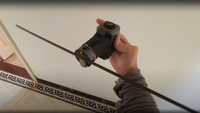
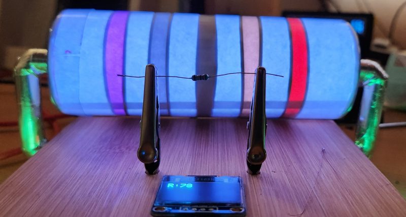
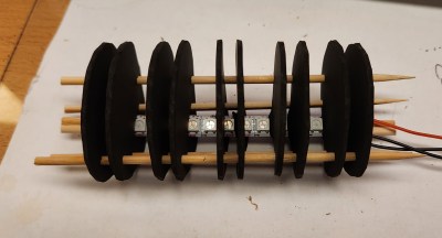
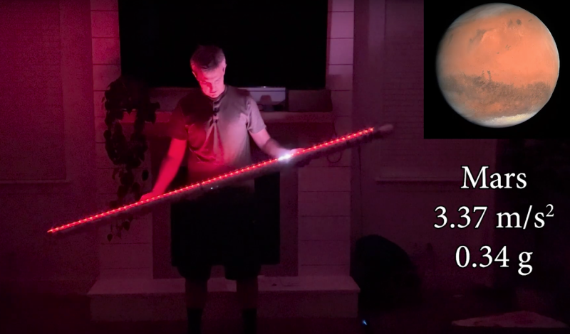
The simulator itself largely consists of a row of about 60 NeoPixels, spread out in a line along a length of lightweight PVC pipe. They’re controlled by an Arduino Nano which has a built-in inertial measurement unit, allowing it to sense the angle the pipe is being held at as well as making determinations about its movement. A set of LEDs on the NeoPixel strip is illuminated, which simulates a ball being balanced on this pipe, and motion one way or the other will allow the ball to travel back and forth along its length. With the Earth gravity setting this is fairly intuitive but when the gravity simulation is turned up for heavier planets or turned down for lighter ones the experience changes dramatically. Most of the video explains the math behind determining the effects of a rolling ball in each of these environments, which is worth taking a look at on its own.

While the device obviously can’t change the mass or the force of gravity by pressing a button, it’s a unique way to experience and feel what a small part of existence on another world might be like. With enough budget available there are certainly other ways of providing training for other amounts of gravity like parabolic flights or buoyancy tanks, although one of the other more affordable ways of doing this for laypeople is this low-gravity acrobatic device.

Hack a Day 28 Jul 06:00

LED Tester Also Calculates Resistor For Target Voltage

[mircemk] built a slick-looking LED tester with a couple handy functions built in. Not only can one select a target current to put through an LED, but by providing a target voltage, the system will automatically calculate the necessary series resistor. If for example the LED is destined for 14 V, this device will not only show how the LED looks at the chosen current, but will calculate the required resistor to get the same results on a 14 V system.

The buttons on the left control the target current and the voltage of the destination system. Once an LED is connected it will light up and the display indicates the LED’s forward voltage, the LED current, and the calculated series resistor value to obtain the same result at the selected target voltage. It’s a handy way to empirically dial in LED brightness values without needing to actually set up any particular test environment.

On the inside there’s little more than a handful of passive components, an Arduino, an LCD display, and a few buttons. This kind of tool reminds us of the highly clever component testers that hit the hobbyist scene years ago, showing what kind of advanced tricks a modern microcontroller is capable of with the right programming. (Here’s a look at how those work, if you’re interested in some deeper details.)

[mircemk] demonstrates his tool in the video, embedded below. We particularly like the attention he paid to the enclosure, giving it a very functional layout. It goes to show that when designing something, it’s never too early to consider enclosure and UI layout.

Smooth Animations, Slick Bar Graphs, but No Custom Characters on This 16×2 OLED

Sometimes, finding new ways to use old hardware requires awesome feats of reverse engineering, software sleight of hand, and a healthy dose of good fortune. Other times, though, it’s just as simple as reading the data sheet and paying attention to details.

Not that we’re knocking [upir]’s accomplishment with these tricked-out 16×2 OLED displays. Far from it, in fact — the smoothly animated bar graph displays alphanumerics look fantastic. What’s cool about this is that he accomplished all this without resorting to custom characters. We’ve seen him use this approach before; this time around, the hack involves carefully shopping for a 16×2 OLED display with the right driver chip — a US2066 chip. You’ll still need a few tricks to get things working, like extra pull-up resistors to get the I2C display talking to an Arduino, plus a little luck that you got a display with the right character ROM.

Once all that is taken care of, getting the display to do what you want is mainly a matter of coding. In the video below, [upir] does a great job of walking through the finer points, and the results look great. The bar graphs in particular look fantastic, with silky-smooth animations.

Hack a Day 27 Apr 21:00
16x2  animation  arduino  display  led hacks  oled  rom  us2066  

Tidy POV Display Using The ESP32

Chinese Youtuber [corebb] presents the second version of his POV display. The earlier version used 5050-sized SMT addressable LEDs, which didn’t give great resolution, so he rev’d the design to use a much higher number (160 to be exact) of APA102 LEDs. These are 2mm on the side, making them a little more difficult to handle, so after some initial solder paste wobbles, he decided to use a contract assembly house to do the tricky bit for him. This failed as they didn’t ‘understand’ the part and placed them the wrong way around! Not to be deterred, he had another go with a modified solder stencil, and eventually got the full strip to light up correctly.

Based on an ESP32 (using the Arduino stack) and SDCard for control, and a LiPo cell charged wirelessly, the build is rather tidy. A couple of hall effect switches are mounted at the start of each of the two arms, presumably lining

Real-time video streaming? Check!

up with a magnet on the case somewhere, although this isn’t clear. The schematic and PCB appear to have been designed with JLCEDA, which is a repackaging of EasyEDA. We can see the attraction with the heavy integration of this with the JLC and LCSC services. It appears that he even managed to get streamed video working — showing a live video from a webcam — which is quite an undertaking to pull off when you think how much processing needs to happen in real-time. As he alludes to in the video, trying to increase the resolution beyond this point is not viable with the processing capability of the ESP32.

A resin-printed case finishes off the build, with a screw-thread mount added to the rear, to allow typical camera mounts to be used to hold the thing down. A smart move we think.

We love POV displays around here, this spherical POV display is especially fabulous, but you don’t need fancy hardware if you have a handy ceiling fan and a bit of protoboard spare.

Thanks to [mrx23dot] for the tip!

Hack a Day 24 Nov 00:00

The Great Resistor Embiggens the Smallest Value

With surface-mount components quickly becoming the norm, even for homebrew hardware, the resistor color-code can sometimes feel a bit old-hat. However, anybody who has ever tried to identify a random through-hole resistor from a pile of assorted values will know that it’s still a handy skill to have up your sleeve. With this in mind, [j] decided to super-size the color-code with “The Great Resistor”.

How the resistor color-code bands work

At the heart of the project is an Arduino Nano clone and a potential divider that measures the resistance of the test resistor against a known fixed value. Using the 16-bit ADC, the range of measurable values is theoretically 0 Ω to 15 MΩ, but there are some remaining issues with electrical noise that currently limit the practical range to between 100 Ω and 2 MΩ.

[j] is measuring the supply voltage to help counteract the noise, but intends to move to an oversampling/averaging method to improve the results in the next iteration.

The measured value is shown on the OLED display at the front, and in resistor color-code on an enormous symbolic resistor lit by WS2812 RGB LEDs behind.

Inside The Great Resistor, the LEDs and baffle plates make the magic work

Precision aside, the project looks very impressive and we like the way the giant resistor has been constructed. It would look great at a science show or a demonstration. We’re sure that the noise issues can be ironed out, and we’d encourage any readers with experience in this area to offer [j] some tips in the comments below. There’s a video after the break of The Great Resistor being put through its paces!

If you want to know more about the history of the resistor color code bands, then we have you covered.  Alternatively, how about reading the color code directly with computer vision?

Plumbing Valves as Heavy Duty Analog Inputs

Input devices that can handle rough and tumble environments aren’t nearly as varied as their more fragile siblings. [Alastair Aitchison] has devised a brilliant way of detecting inputs from plumbing valves that opens up another option. (YouTube) [via Arduino Blog]

While [Aitchison] could’ve run the plumbing valves with water inside and detected flow, he decided the more elegant solution would be to use photosensors and an LED to simplify the system. This avoids the added cost of a pump and flow sensors as well as the questionable proposition of mixing electronics and water. By analyzing the change in light intensity as the valve closes or opens, you can take input for a range of values or set a threshold for an on/off condition.

[Aitchison] designed these for an escape room, but we can see them being great for museums, amusement parks, or even for (train) simulators. He says one of the main reasons he picked plumbing valves was for their aesthetics. Industrial switches and arcade buttons have their place, but certainly aren’t the best fit in some situations, especially if you’re going for a period feel. Plus, since the sensor itself doesn’t have any moving parts, these analog inputs will be easy to repair should anything happen to the valve itself.

If you’re looking for more unusual inputs, check out the winners of our Odd Inputs and Peculiar Peripherals contest or this typewriter that runs Linux.

RGB LED Matrix Helps Etch-a-Sketch Scratch Out a 21st Century Existence

We never did crack open our Etch-a-Sketch, but we did scrape out a window large enough to really check out the mechanism inside. [MrLangford] is bringing the Etch-a-Sketch into the 21st century while at the same time, bringing an even bigger air of mystery, at least for the normies.

Instead of scraping aluminum powder off of plastic by driving a stylus on an x-y gantry with a pair of knobs, this bad boy uses rotary encoders to move the cursor around and put down squares of colored light. The familiar movements are there — the left knob moves the cursor left and right, and the right knob moves it up and down. But this wouldn’t be a 21st century toy without newfangled features. Push the left encoder down and it cycles through eight color choices, or push the right one down to go through them backwards. We hope one of the colors is setting it back to darkness in case you screw up. And while we’re dreaming up improvements, it would be awesome to add an accelerometer so you could shake it clear like a standard Etch-a-Sketch.

Inside the requisite red enclosure with white knobs are an Arduino Nano and a 16×16 RGB LED matrix. The enclosure is four sheets of 6mm MDF glued together, and we like the use of protoboard to distribute GND and 5 V in the name of keeping the thing slim.

If you’re not much of an artist, here’s a TV-sized Etch-a-Sketch build that can draw by itself.

Jigsaw Puzzle Lights Up With Each Piece

Putting the last piece of a project together and finally finishing it up is a satisfying feeling. When the last piece of a puzzle like that is a literal puzzle, though, it’s even better. [Nadieh] has been working on this jigsaw puzzle that displays a fireworks-like effect whenever a piece is placed correctly, using a lot of familiar electronics and some unique, well-polished design.

The puzzle is a hexagonal shape and based on a hexagonally symmetric spirograph, with the puzzle board placed into an enclosure which houses all of the electronics. Each puzzle piece has a piece of copper embedded in a unique location so when it is placed on the board, the device can tell if it was placed properly or not. If it was, an array of color LEDs mounted beneath a translucent diffuser creates a lighting effect that branches across the entire board like an explosion. The large number of pieces requires a multiplexer for the microcontroller, an ATtiny3216.

This project came out of a FabAcademy, so the documentation is incredibly thorough. In fact, everything on this project is open sourced and available on the project page from the code to the files required for cutting out the puzzle pieces and the enclosure. It’s an impressive build with a polish we would expect from a commercial product, and reminds us of an electrified jigsaw puzzle we saw in a previous build.

Thanks to [henk] for the tip!

Transmit Your Gaze to This Fiber Optic LED Lamp

Call us easily amused, but we think it’s pretty amazing what can be done with a microcontroller, some RGB LEDs, and a little bit of plastic. Case in point is [andrei.erdei]’s beautiful and quite approachable fiber optic LED lamp. It’s a desktop-friendly version of a similar piece [andrei] made that is roughly nine times the size of this one and hangs on the wall. The build may be simple, but the product is intricately lovely.

We really like the visual density of this lamp — it’s just the right amount of tubes and strikes a balance between being too sparse and too chaotic. As you might expect, there’s an Arduino and some RGB LED strips involved. But the key to this build is in the 16 pieces of side-glow plastic fiber optic tubing. Side-glow is designed to let light escape along the length of the tube as opposed to end-glow, which is made to minimize light loss from one end to the other like a data pipe. This allows for all sorts of fun effects, and you can watch [andrei.erdei] go slowly and soothingly through the different colors and modes in the demo video after the break. Make sure you watch long enough to see the tubes move like the old Windows 3D pipes screensaver

Already have too many knickknacks and wall hangings? You’re missing out on prime real estate — the ceiling. Check out this fiber optic ceiling installation that reacts to music.

LED Hourglass Moves Like the Real Thing

If you want to waste time in a meaningful way, get yourself an hourglass. It’s simultaneously mesmerizing and terrifying to sit there and watch the seconds slip through the threshold that separates possibility from missed opportunity.

[Ty and Gig]’s LED hourglass is equally beautiful to watch. It doesn’t actually tell time, but that’s perfectly fine by us. What it does do is animate the LEDs to approximate grains of sand in gravity, no matter how the hourglass is tilted.

In either vertical orientation, the sand falls as long as there is some in the top. When the hourglass is horizontal, the LEDs settle just like real sand does. [Ty and Gig] achieved this with a whole lot of code that breaks the animation frames into structure arrays.

By contrast, the hardware part of this build is fairly simple: all that’s needed to replicate this build is some RGB LEDs a beefy power supply to drive them, an accelerometer, and a microcontroller.

[Ty and Gig] were planning to use an ESP8266, but misplaced it and went with an Arduino Mega instead. (You know what they say — buy a replacement and the one you lost will turn up almost immediately.) The beautiful frame is made from leftover purpleheart, a hardwood that turns purple with exposure to air. Check out the build video after the break.

Too lazy to reset your hourglass every hour? Here’s one that flips itself.