Posts with «resistor» label

The Great Resistor Embiggens the Smallest Value

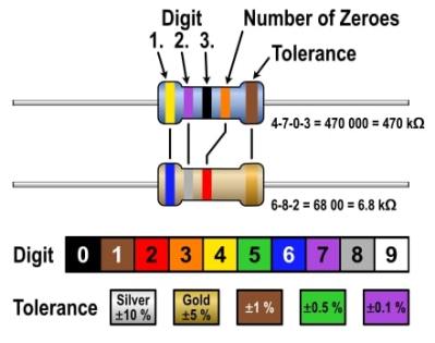
With surface-mount components quickly becoming the norm, even for homebrew hardware, the resistor color-code can sometimes feel a bit old-hat. However, anybody who has ever tried to identify a random through-hole resistor from a pile of assorted values will know that it’s still a handy skill to have up your sleeve. With this in mind, [j] decided to super-size the color-code with “The Great Resistor”.

How the resistor color-code bands work

At the heart of the project is an Arduino Nano clone and a potential divider that measures the resistance of the test resistor against a known fixed value. Using the 16-bit ADC, the range of measurable values is theoretically 0 Ω to 15 MΩ, but there are some remaining issues with electrical noise that currently limit the practical range to between 100 Ω and 2 MΩ.

[j] is measuring the supply voltage to help counteract the noise, but intends to move to an oversampling/averaging method to improve the results in the next iteration.

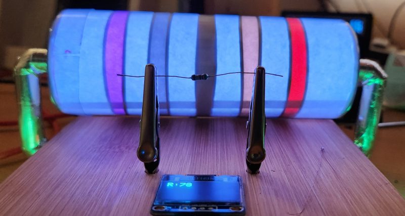
The measured value is shown on the OLED display at the front, and in resistor color-code on an enormous symbolic resistor lit by WS2812 RGB LEDs behind.

Inside The Great Resistor, the LEDs and baffle plates make the magic work

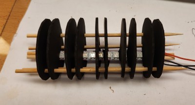
Precision aside, the project looks very impressive and we like the way the giant resistor has been constructed. It would look great at a science show or a demonstration. We’re sure that the noise issues can be ironed out, and we’d encourage any readers with experience in this area to offer [j] some tips in the comments below. There’s a video after the break of The Great Resistor being put through its paces!

If you want to know more about the history of the resistor color code bands, then we have you covered.  Alternatively, how about reading the color code directly with computer vision?

Resistors Sorter Measures Values

We’ve all been there. A big bag of resistors all mixed up. Maybe you bought them cheap. Maybe your neatly organized drawers spilled. Of course, you can excruciatingly read the color codes one by one. Or use a meter. But either way, it is a tedious job. [Ishann’s] solution was to build an automatic sorter that directly measures the value using a voltage divider, rather than rely on machine vision as is often the case in these projects. That means it could be modified to do matching for precise circuits (e.g., sort out resistors all marked 1K that are more than a half-percent away from one nominal value).

There is a funnel that admits one resistor at a time into a test area where it is measured. A plate at the bottom rotates depending on the measured value. In the current implementation, the resistor either falls to the left or the right. It wouldn’t be hard to make a rotating tray with compartments for different values of resistance. It looks like you have to feed the machine one resistor at a time, and automating that sounds like a trick considering how jumbled loose axial components can be. Still, its a fun project that you probably have all the parts to make.

An Arduino powers the thing. An LCD screen and display control the action. If you want some practice handling material robotically, this is a great use of servos and gravity and it does serve a practical purpose.

We have seen many variations on this, including ones that read the color code. If you ever wanted to know where the color code for resistors came from, we took a trip to the past to find out earlier this year.

Hackaday Links: July 12, 2015

Adafruit is working on a series of videos that’s basically Sesame Street for electronics. G is for Ground is out, where [Adabot] discovers pipes and lightning rods are connected to ground. Oh, the rhyming. Here’s the rest of the videos so far. We can’t wait for ‘Q is for Reactive Power’.

Think you’re good enough to build an airlock 70 cubic meters in volume that can cycle once every thirty seconds? How about building a 500 mile long steel tube with zero expansion joints across active fault lines? Can you stop a 3 ton vehicle traveling at 700 miles per hour in fifteen seconds? These are the near-impossible engineering challenges demanded of the hyperloop. The fact that no company will pay for this R&D should tell you something, but that doesn’t mean you still can’t contribute.

Calling everyone that isn’t from away. [Paul] lives near Augusta, Maine and can’t find a hackerspace. Augusta is the capital of the state, so there should be a hackerspace nearby. If you’re in the area, go leave a message on his profile.

Last week we found memristors you can buy. A few years ago, [Nyle] found them while hiking. They were crudded up shell casings, and experiments with sulfur and copper produced a memristor-like trace on a curve tracer.

Need a way to organize resistors? Use plastic bags that are the same size as trading cards.

The Arduino is too easy. It must be packaged into a format that is impossible to breadboard. It should be shaped like a banana. Open source? Don’t need that. The pins are incorrectly labelled, and will be different between manufacturing runs.


Filed under: Hackaday Columns, Hackaday links

QRD1114 Resistor Values

Hi all,

I'm using a QRD1114 sensor for a line-follower. Datasheet: http://www.fairchildsemi.com/ds/QR/QRD1114.pdf

Im hooking it up with this schematic:

However, I'm unsure how the value for the 10K resistor was calculated? It's acting as a potential divider, right?

For the LED im guessing that the value of 220 was taken from doing:

R=(Input Voltage - Max Forward Voltage)/(Optimum forward current)

read more