Posts with «nixie» label

Noble Graphs: Displaying Data With Neon Like Its 1972

In the days before every piece of equipment was an internet-connected box with an OLED display, engineers had to be a bit more creative with how they chose to communicate information to the user. Indicator lights, analog meters, and even Nixie tubes are just a few of the many methods employed, and are still in use today. There are, however, some more obscure (and arguably way cooler) indicators that have been lost to time.

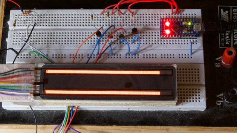
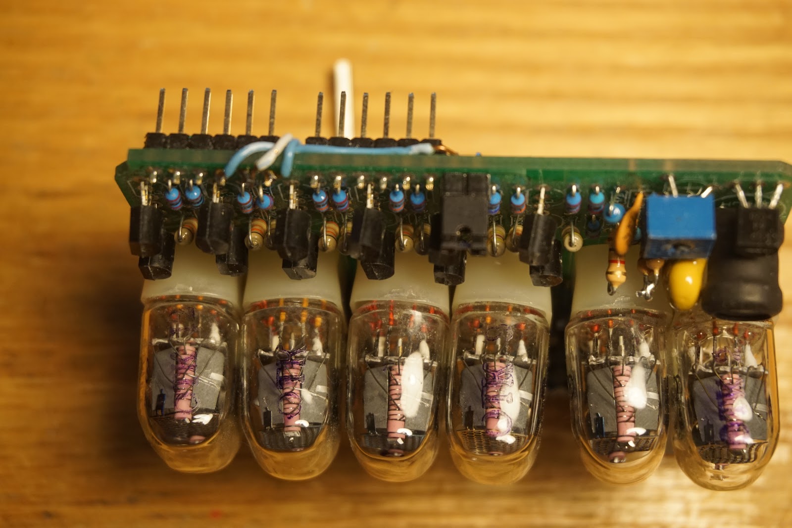
[Aart Schipper] unearthed one such device while rummaging around in his father’s shed: a pair of Burroughs Bar Graph Glow-Transfer Displays. These marvelous glowing rectangles each have two bars (think the left and right signals on an audio meter, which is incidentally what they were often used for), each with 201 neon segments. Why 201, you may ask? The first segment on each bar is always illuminated, acting as a “pilot light” of sorts. This leaves 200 controllable segments per channel. Each segment is used to “ignite” its neighboring segment, something the manufacturer refers to as the “Glow-Transfer Principle.” By clever use of a three-phase clock and some comparators, each bar is controlled by one analog signal, keeping the wire count reasonably low.

Don’t get us wrong, the warm, comforting glow of Nixie tubes will always have a special place in our hearts, but neon bar graphs are just hard to beat. The two do have a similar aesthetic though, so here’s hoping we see them used together in a project soon.

Thanks to [Jan] for the tip!

Hack a Day 18 Oct 03:00
arduino  neon  nixie  parts  retro  

Upcycled Nixie Clock Fit For A Friend

Building a clock from parts is a right of passage for makers, and often represents a sensible introduction into the world of electronics. It’s also hard to beat the warm glow of Nixie tubes in a desktop clock, as [Joshua Coleman] discovered when building a Nixie tube clock for a friend.

The original decision to upcycle the chassis from an unrepairable Heathkit function generator came a little undone after some misaligned cutting, so the front panel ended up being redesigned and 3D printed. This ended up being serendipitous, as the redesigned front panel allowed the Nixie tubes to be inset within the metal chassis. This effect looks great, and it also better protects the tubes from impact damage.

Sourcing clones of the 74141 Nixie driver ICs ended up being easier than anticipated, and the rest of the electronics came together quickly. The decoders are driven by an Arduino, and the IN-4 Nixie tubes are powered by a bespoke 170 volt DC power supply.

Unfortunately four of the tubes were damaged during installation, however replacements were readily available online. The gorgeous IN-4 Nixie tube has a reputation for breaking easily, but is priced accordingly on auction sites and relatively easy to source.

The build video after the break should get any aspiring Nixie clock makers started, but the video description is also full of extra information and links for those needing help getting started.

We’re not short on clock hacks here at Hackaday, so why not check out a couple more? This retro-inspired LED clock looks like its right out of a parallel universe, or maybe this stunning Nixie clock driven by relays will strike your fancy.

Hack a Day 08 Apr 00:00

Rothko Clock Nixie Shield with 6 IN-17 tubes

This compact 6-tube Nixie shield was designed by Tyler a long time ago, when kickstarter was young, and I was following closely and contributing often. Soon after the successful campaign, this open source project, together with its supporting documentation and web site, seemed to have disappeared from the internet.
I already reviewed the Nixie shield here (as part of the "Rothko" clock), and covered it a bit more in another post.
Since I found it appealing, both as a soldering kit and as a miniature Nixie board, I also:
  • modified slightly the original schematic (eliminated the under-the-tube LEDs)
  • redesigned the PCB
  • named the clock "Rothko", to accompany my other clocks in the masters series, "Mondrian" and "Kandinsky". Note that, in this case, the "Rothko" clock is the union of 2 boards: this 6-tube Nixie shield and wsduino (which itself can be replaced by any Arduino with an RTC).


A kit for the Nixie shield is offered on Tindie. The PCB was designed to be self explanatory, but some people prefer the safety of assembly instructions. The slides below, recycled from the original deck, show the sequence of steps.


Once fully assembled, plug the Nixie shield into your Arduino, then upload this basic clock sketch (reads RTC and displays hours and seconds; no setting buttons, no Bluetooth, no buzzer/alarm):

#include "Arduino.h"
#include "avr/pgmspace.h"
#include "Wire.h"
#include "DS1307.h"
#include "avr/io.h"
#include "avr/interrupt.h"

// global variables
unsigned char INDEX = 1;   /* 1 to 6 */
unsigned char HOUR  = 7;   /* 1 to 12 */
unsigned char MINUTE = 45;  /* 0 to 59 */
unsigned char SECOND = 23;  /* 0 to 59 */

boolean is12HMode = false;


// read time from DS1307 at intervals;

#define MAX_TIME_READING_COUNTER  15000
long timeReadingCounter = MAX_TIME_READING_COUNTER;


// timer2 used for nixie tube multiplexing

ISR(TIMER2_COMPA_vect)
{
/* HOUR = 10, 11, or 12 or top of minute?*/
if ((HOUR / 10) || SECOND==0)
{
PORTB = 0x10;  // turn HOUR tens LED on
}
else
{
PORTB = 0x00;  // turn HOUR tens LED off
}

switch(INDEX++)

{
/* HOUR tens place */
case 1:
/* blank anodes */
PORTD = 0x00;

/* set cathode */

PORTB |= (HOUR / 10);

/* only turn anode on if one */

if (HOUR / 10)
{
PORTD = 0x04;    
}
break;

/* HOUR ones place */

case 2:
/* blank anodes */
PORTD = 0x00;

/* set cathode */

PORTB |= (HOUR % 10);

/* turn on anode */

PORTD = 0x08;
break;

/* MINUTE tens place */

case 3:
/* blank anodes */
PORTD = 0x00;

/* set cathode */

PORTB |= (MINUTE / 10);

/* turn on anode */

PORTD = 0x10;
break;

/* MINUTE ones place */

case 4:
/* blank anodes */
PORTD = 0x00;

/* set cathode */

PORTB |= (MINUTE % 10);

/* turn on anode */

PORTD = 0x20;
break;

/* SECOND tens place */

case 5:
/* blank anodes */
PORTD = 0x00;

/* set cathode */

PORTB |= (SECOND / 10);

/* turn on anode */

PORTD = 0x40;
break;

/* SECOND ones place */

case 6:
/* blank anodes */
PORTD = 0x00;

/* set cathode */

PORTB |= (SECOND % 10);

/* turn on anode */

PORTD = 0x80;

/* reset index */

INDEX = 1;
break;
}
}

void setup()
{
// configure pins
pinMode(2, OUTPUT);
pinMode(3, OUTPUT);
pinMode(4, OUTPUT);
pinMode(5, OUTPUT);
pinMode(6, OUTPUT);
pinMode(7, OUTPUT);
pinMode(8, OUTPUT);
pinMode(9, OUTPUT);
pinMode(10, OUTPUT);
pinMode(11, OUTPUT);
pinMode(12, OUTPUT);

cli();  // disable global interrupts


// timer2 1kHz interrupt

TCCR2A = 0x00;
TCCR2B = 0x00;
TCNT2 = 0x00;
OCR2A = 0xF9;
TCCR2A |= (1 << WGM21);
TCCR2B |= (1 << CS22);
TIMSK2 |= (1 << OCIE2A);

sei(); // enable global interrupts

}

void loop()
{
    timeReadingCounter++;
    if (timeReadingCounter > MAX_TIME_READING_COUNTER)
    {
      getTimeFromRTC();
      timeReadingCounter = 0;
    }
}

void getTimeFromRTC()
{
int16_t rtc[7];

RTC_DS1307.get(rtc, true);


SECOND = rtc[0];

MINUTE = rtc[1];
HOUR = rtc[2];
if (is12HMode && HOUR > 12)
HOUR = HOUR - 12;
}

void setTime(int hour, int minute, int second)
{
  RTC_DS1307.stop();
  RTC_DS1307.set(DS1307_SEC, second);
  RTC_DS1307.set(DS1307_MIN, minute);
  RTC_DS1307.set(DS1307_HR, hour);
  RTC_DS1307.start();
}


Wise time with Arduino 12 Mar 02:45
nixie  

Nixie Clock Claims to be Simplest Design

[Engineer2you] built a nixie tube clock and claims it is the simplest design. We felt like that was a challenge. In this design, the tubes are set up as a matrix with optoisolators on each row and column. With 60 segments, the matrix allows you to control it all with 16 bits. There are six columns, each corresponding to a digit. That means each row has 10 lines.

The Arduino code reads the clock and produces the output to the tubes fast enough that your eye perceives each digit as being always on, even though it isn’t.

It may be semantics, but part of what makes the design simple isn’t that it is simple on its own, but that it does use a small number of dense modules. For example, the clock is a DS3231, and there is a DC step up board to generate 390V for the tubes. So instead of minimizing part count, this design really minimizes how many parts you have to connect by employing modules, including the Arduino. That’s still something, though.

It looks as though the nixie tubes used are of Soviet origin. They need no more than 170V to ignite and at least 120V to stay lit. Not a problem with a simple DC to DC converter since the current is very low — on the order of 2.5 mA or so.

We suppose one day the stock of nixie tubes will be gone. But there are still people making them. Or you can do a modern version with light pipes.

Hack a Day 15 Feb 06:00

Arduino Shield Makes Driving Nixies Easy

Nixie tubes are adored by hackers across the world for their warm glow that recalls an age of bitter nuclear standoffs and endless proxy wars. However, they’re not the easiest thing to drive, requiring high voltages that can scare microcontrollers senseless. Thankfully, it’s possible to score an Arduino shield that does the heavy lifting for you.

The HV supply is the heart of any Nixie driver.

The shield uses HV5812 drivers to handle the high-voltage side of things, a part more typically used to drive vacuum fluorescent displays. There’s also a DHT22 for temperature and humidity measurements, and a DS3231 real time clock. It’s designed to work with IN-12 and IN-15 tubes, with the part selection depending on whether you’re going for a clock build or a combined thermometer/hygrometer. There’s also an enclosure option available, consisting of two-tone laser etched parts that snap together to give a rather sleek finished look.

For those looking to spin up their own, code is available on Github and schematics are also available. You’ll have to create your own PCB of course, but there are guides that can help you along that path. If you’re looking to whip up a quick Nixie project to get your feet wet, this might just be what you need to get started. Of course, you can always go straight to hard mode, and attempt a functional Nixie watch. Video after the break.

Slot

Debugging the IN-17 Nixie clock (aka "Rothko clock")

This weekend I felt like doing something, which rarely happens lately. From the pile of semi-failed ("started but not finished", "finished but not working", "not fully functional" etc.) I picked the Nixie clock with 6 IN-17 tubes. Its problem was that it did not display any 6 nor 7, on all tubes. A quick check with the meter showed, indeed, a short between 2 neighbor pins. Upon visual inspection (not as easy as it used to be) and with a lot of luck (and magnification), I found the culprit: one tube in the middle of them all had two pins crossed (inverted), as shown in the photo below.


Here is the board with the IN-17 removed.


Since it was impossible for me to re-insert the old short-pined IN-17 (because of the tight space), I had to use a new one. Everything turned out well in the end.

Now onto the usability of this pretty Nixie clock. The only way to set the time is to send commands from a Bluetooth device (phone, tablet). This is not very "user friendly", nor quick, is it? The obvious "remedy" to this situation was to add a couple of buttons on top, where they can be easily pressed. As you may know from my old post, the high voltage (170V) for powering the IN-17 tubes is generated in the same top-of-the-board area, definitely not a good place for fingers. The solution was to use a longer piece of prototyping PCB to cover the danger zone.


As in most simple clocks, the right button increments the minutes, the left one increments the hours, while the seconds are always reset.

I also added a hardware "12 hour mode" through the use of a jumper placed at the bottom of the board:


With the jumper off, the clock shows military time (the hours between 0 and 23).

Unlike the first version, this new Nixie clock, which I shall name "Rothko clock" from now on, uses just 2 boards: wsduino (with on-board RTC and XBee support, assembled for 9V power) and the Nixie shield itself. The 2-button hack should be made somehow permanent, probably by adding them onto the Nixie shield, similar to the LED matrix mini display shield used in the Mondrian clock. Also note that the alarm feature won't work (although implemented in the code, shared here) since there is no buzzer. Bluetooth should still work with a BTBee module plugged into its wsduino socket.

Interestingly, after all these years, one "new old stock" IN-17 Nixie tube can still be bought on ebay for about $7 (compared with about $2 for the bigger IN-12s).

Here are a few more detail photos on the wires that connect the buttons:


The hour buttons (on the left) is connected to A1.
The minutes button (right side) is connected to A0.
The "12/24H mode" header pins (with jumper, at the bottom side of the board) are connected to A2 and GND. Jumper on means pin A2 to the ground, thus enabling 12H mode.


Wise time with Arduino 17 Mar 20:16
hacking  nixie  

LED “Nixie” Display

Laser-cut and edge-lit, these 10-digit numeric displays are bigger, brighter, and safer than the old tubes.

Read more on MAKE

The post LED “Nixie” Display appeared first on Make: DIY Projects and Ideas for Makers.

A DIY Arduino Nixie tube clock

Nixie tubes have a lot of fans because of their retro style. They are neon valve tubes, where 10 cathodes shaped like numbers from 0 to 9 are switched on by plasma when high voltage flows through them. Patented in the 1930s by H.P. Boswau, they were wildly popular in the ‘60s and remained so until LEDs became cheaper to manufacture in the ‘70s. Many Makers today are creating vintage-look clocks using, now rare, Nixies bought on eBay with the help of an Arduino or Genuino Uno to control them.

In the video below, Jozsef Kovecses built a Nixie clock with NTP time syncronization using a Genuino Uno, a Geeetech IduinoShield, DS1307 RTC, DC-to-DC converter, and Nixie tube modules to drive the tubes directly.

Arduino Blog 15 Jun 11:55

Nixie Tube Energy Meter Dresses up Front Hall

When you move into a new house, there’s always something that needs fixing up. A bit of paint and some new drapes may help freshen up the place and put your mark on it, but things like exposed wiring and a very utilitarian looking electrical panel in your front hall are altogether different. Unwilling to live with the mess, [John Whittington] decided to enclose his utility panel and add a Nixie tube IoT watt meter to dress things up while monitoring energy usage.

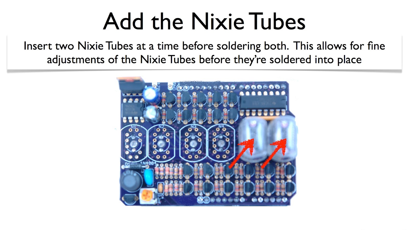
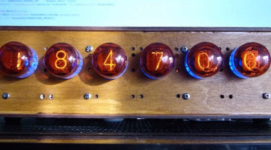
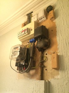
Looking at the “before” pictures on [John]’s blog, we can see why he’d want to invest the effort – not exactly an attractive way to greet guests at the front door. A simple wooden box to replace the previous cover would have sufficed, but why pass up the opportunity to add value? [John] opted for a Nixie tube display to complement the glass of the electric meter. The Nixie modules were a bit on the pricey side, though, so with only a pair of tubes to work with, [John] came up with a clever system to indicate the scale of the display. We doubt he’ll ever see megawatt-level instantaneous power draw, but the meter is also capable of totalling energy use, and as a bonus an ESP-8266 gives lets him stream data to the web.

We’ve featured tons of Nixie projects before – everything from clocks to cufflinks. We have to agree that [John]’s Nixie project turned out great, and it’s sure to be a conversation starter with arriving guests.


Filed under: Arduino Hacks, home hacks