Debugging the IN-17 Nixie clock (aka "Rothko clock")
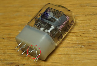
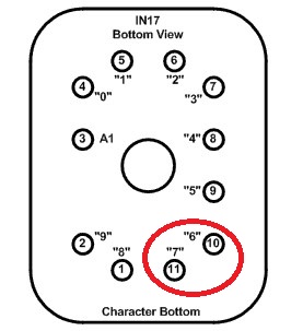
This weekend I felt like doing something, which rarely happens lately. From the pile of semi-failed ("started but not finished", "finished but not working", "not fully functional" etc.) I picked the Nixie clock with 6 IN-17 tubes. Its problem was that it did not display any 6 nor 7, on all tubes. A quick check with the meter showed, indeed, a short between 2 neighbor pins. Upon visual inspection (not as easy as it used to be) and with a lot of luck (and magnification), I found the culprit: one tube in the middle of them all had two pins crossed (inverted), as shown in the photo below.
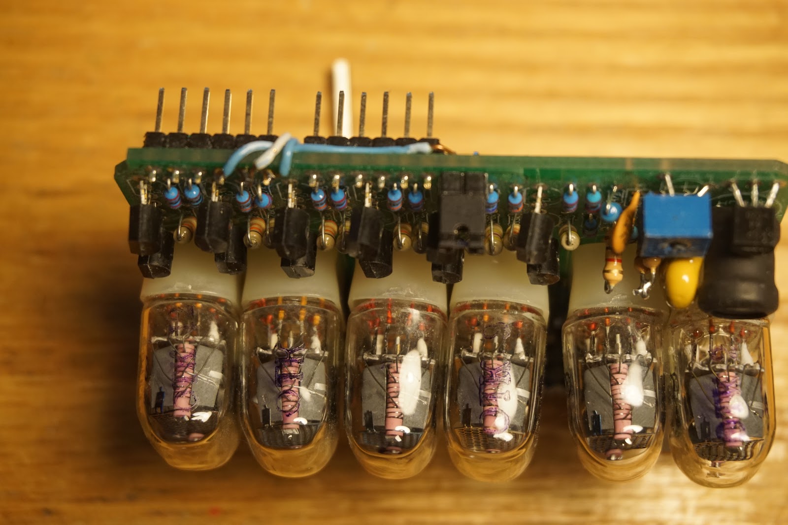
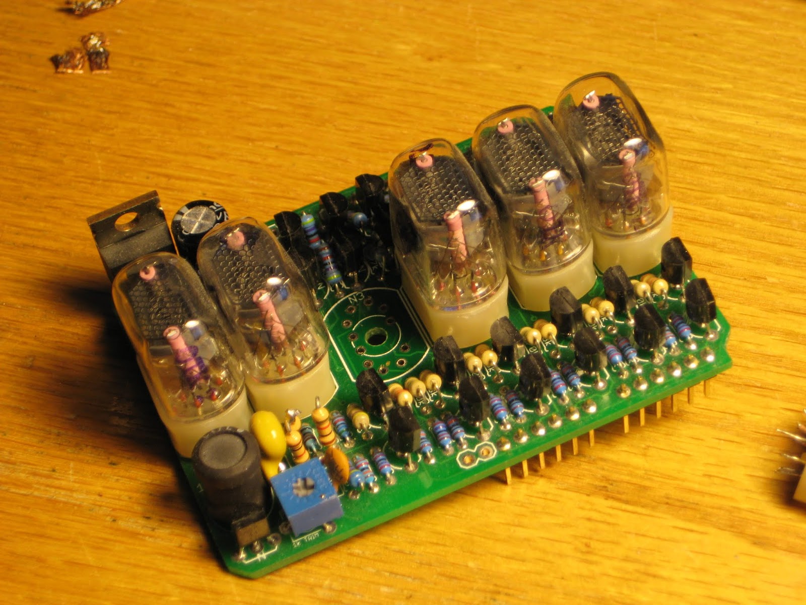
Here is the board with the IN-17 removed.

Since it was impossible (at least for me) to re-insert the old short-pined IN-17 (because of the tight space), I had to use a new one. Everything was well in the end.
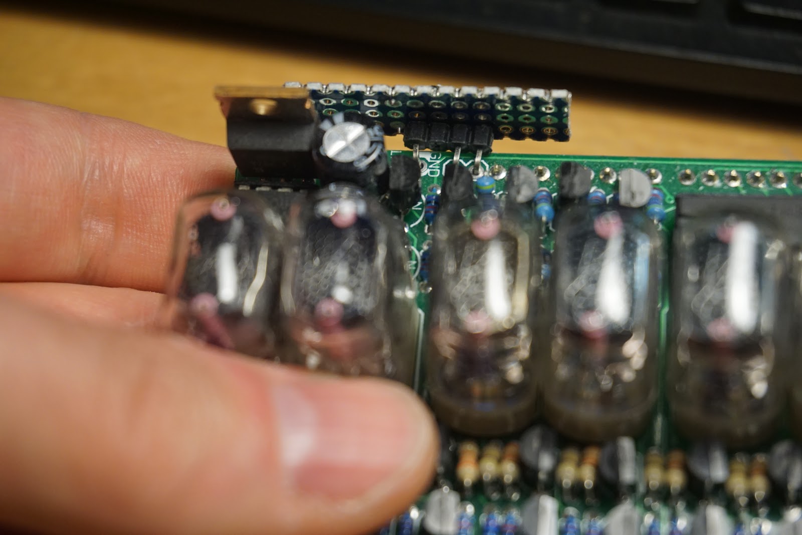
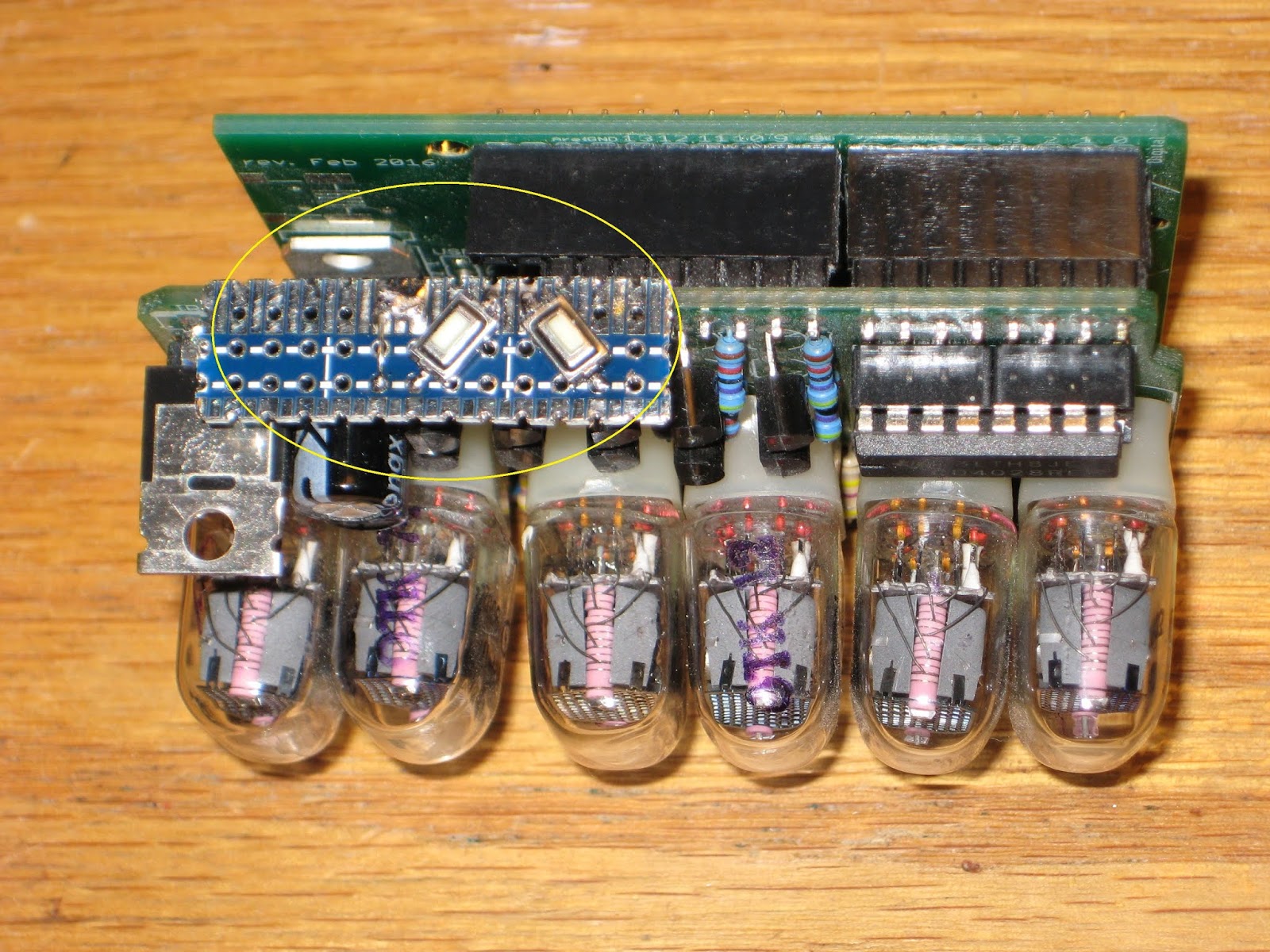
Now onto the usability of this pretty Nixie clock. The only way to set the time is to send commands from a Bluetooth device (phone, tablet). This is not very "user friendly", nor quick, is it? The obvious "remedy" to this situation was to add a couple of buttons on top, where they can be easily pressed. As you may know from my old post, the high voltage (170V) for powering the IN-17 tubes is generated in the same top-of-the-board area, definitely not a good place for fingers. The solution was to use a longer piece of prototyping PCB to cover the danger zone.

As in most simple clocks, the right button increments the minutes, the left one increments the hours, while the seconds are always reset.
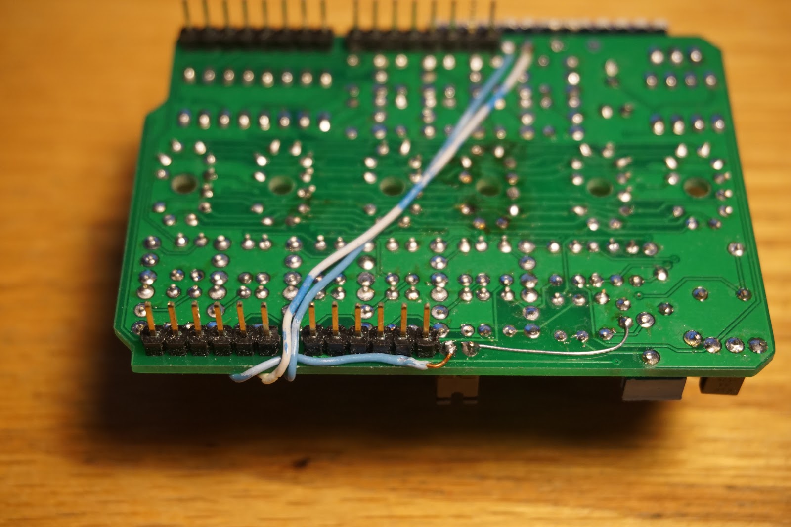
I also added a hardware "12 hour mode" through the use of a jumper placed at the bottom of the board:

With the jumper off, the clock shows military time (the hours between 0 and 23).
Unlike the first version, this new Nixie clock (I shall name it "Rothko clock" from now on) uses just 2 boards: wsduino (with on-board RTC and XBee support) and the Nixie shield itself. The 2-button hack should be made somehow permanent, probably by adding them onto the Nixie shield, similar to the LED matrix mini display shield used in the Mondrian clock. Also note that the alarm feature won't work (although implemented in the code, shared here) since there is no buzzer. Bluetooth should still work with a BTBee module plugged into its wsduino socket.


Here is the board with the IN-17 removed.
Since it was impossible (at least for me) to re-insert the old short-pined IN-17 (because of the tight space), I had to use a new one. Everything was well in the end.
Now onto the usability of this pretty Nixie clock. The only way to set the time is to send commands from a Bluetooth device (phone, tablet). This is not very "user friendly", nor quick, is it? The obvious "remedy" to this situation was to add a couple of buttons on top, where they can be easily pressed. As you may know from my old post, the high voltage (170V) for powering the IN-17 tubes is generated in the same top-of-the-board area, definitely not a good place for fingers. The solution was to use a longer piece of prototyping PCB to cover the danger zone.
As in most simple clocks, the right button increments the minutes, the left one increments the hours, while the seconds are always reset.
I also added a hardware "12 hour mode" through the use of a jumper placed at the bottom of the board:

With the jumper off, the clock shows military time (the hours between 0 and 23).
Unlike the first version, this new Nixie clock (I shall name it "Rothko clock" from now on) uses just 2 boards: wsduino (with on-board RTC and XBee support) and the Nixie shield itself. The 2-button hack should be made somehow permanent, probably by adding them onto the Nixie shield, similar to the LED matrix mini display shield used in the Mondrian clock. Also note that the alarm feature won't work (although implemented in the code, shared here) since there is no buzzer. Bluetooth should still work with a BTBee module plugged into its wsduino socket.
[original story: Wise time with Arduino]