Posts with «ikea» label

Smart home gadgets and kitchen tech that make great gifts

Keeping your home clean, organized and secure can be a chore, and your loved ones likely feel the same way. Fortunately, there are gadgets that can help make it a little easier. We review smart speakers, robotic vacuums and Instant Pots all year long, and for the holiday season we’ve compiled a list of our recent favorites in the home tech space that will make excellent gifts. And your giftee doesn’t have to be tech savvy to use all of them either — plenty of our recommendations amount to baby steps into the smart home world for those who would rather start off slow.

Instant Pot Pro

Will Lipman Photography for Engadget / Instant Pot

We almost always recommend the multi-purpose Instant Pot in our holiday gift guides and this year is no exception. But instead of giving your loved one the regular model, why not level up? Designed for avid cook, the Instant Pot Pro brings several key upgrades over previous models. The inner pot has an extra thick bottom that lets you heat it on the stove, plus handles that make it easier to lift. It has 28 customizable programs for different foods, and there are five favorite buttons that you can assign to frequently cooked meals. It also has steam release reminder alerts with 5- and 10-minute pre-sets. It’s available in two different sizes, but we’d recommend the six-quart version for most families.

Buy Instant Pot Pro at Amazon - $130

Anova Precision Cooker Nano

Will Lipman Photography for Engadget

Sous vide cooking essentially means keeping foods in a temperature-controlled water bath, ensuring they’re done to perfection. This used to require expensive equipment, but sous vide cookers have become inexpensive over the past few years. One such device is the Anova Precision Cooker Nano, which can be found for around $100, and can be controlled through either an app or physical buttons. It’s one of the most affordable sous vide machines around, yet it delivers precise temperature controls. The app also comes with an assortment of helpful recipes to help get users started on their sous vide journey.

If you don’t mind spending a bit more, we also like Breville’s Joule for its sleek, minimalist design. It doesn’t have the physical controls that the Nano does, but it makes up for that with its compact form factor that’s a little easier to fit in a kitchen drawer. Either option will ensure medium-rare steak, juicy chicken breasts or just a perfectly soft-cooked egg.

Buy Precision Cooker Nano at Amazon - $130Buy Breville Joule at Amazon - $200

Anova Precision Oven

Anova

If your loved one is a great cook with counter space to spare, consider getting them the Anova Precision Oven. It’s a luxury purchase, for sure, but it’s well worth the price for serious home cooks. This combination convection-steam oven can cook food in both wet and dry heat, letting you control temperature and humidity levels. What this means is that your special someone can make juicy roast chicken with crispy skin as well as crusty artisan-style bread all in one machine. Plus, it has WiFi and a companion app that lets cooks keep an eye on their food from anywhere.

Buy Precision Oven at Anova - $599

Google Nest Doorbell Battery

Nest

Video doorbells are useful for seeing who’s at the front door from the comfort of your couch. One of our favorites is the Nest Hello (now called the Nest Doorbell Wired), which is why we were pleased when Nest came out with a new battery-operated version, the Nest Doorbell Battery. It’s a great gift for both homeowners and renters, as you don’t need to hardwire it. Battery life is anywhere from one to six months depending on how active it is (it’s shorter if you live on a busy street, for example). The Doorbell notifies them whenever there’s a person, animal or vehicle near the front door. It can also let them know when a package has been placed, which is great for pre-empting theft. In addition, it offers three hours of event video history for free, with the option to purchase more space through a Nest Aware subscription.

Buy Nest Doorbell Battery at Best Buy - $180

Google Nest Hub (2nd gen)

Nest

If you do get a Nest Doorbell for someone, you might want to consider gifting them a Nest Hub as well. The two are designed to work together: anytime someone rings the doorbell, the camera view of who’s at the front door will show up on the Nest Hub’s screen. Even without the doorbell, however, the smart display is a great device to have around the home — especially if your loved one already uses the Google Assistant. It works as a digital photo frame and they can use it to watch YouTube and Netflix. It can also make calls via Google Duo and offers recipe videos along with step-by-step cooking instructions. If the user so chooses, they can track their sleeping patterns when they place the device next to their bed.

Buy Nest Hub (2nd gen) at Best Buy - $100

Amazon Echo Show 8

Will Lipman Photography for Engadget

For those who prefer Alexa over the Google Assistant, the Echo Show 8 is a great alternative to the Nest Hub. It also works as a digital photo frame and its 8-inch display is a good size for streaming shows from Amazon Prime, Netflix and Hulu while prepping dinner. It can also be used to keep up with the news, check the weather and control smart home devices. Since Amazon has a partnership with Allrecipes and Food Network Kitchen, users can find assorted recipes and instructional videos as well.

Buy Echo Show 8 at Amazon - $130

Mila Air purifier

Will Lipman Photography for Engadget

Air purifiers are great gifts for anyone who has allergies, lives in a polluted area or just wants to breathe easier at home. And if you want to give someone a smarter air purifier, consider the Mila Air. It ships with one of seven pre-configured HEPA filters that can filter out particles and allergens like pollen and dust. It also has a ton of customization options: there’s a “Housekeeping Service” mode that goes full blast when no one’s in the room, a “Sleep Mode” that turns the lights off and reduces the fan speeds at night, plus a “White Noise” mode that mimics soothing sounds like waterfalls. The Mila also has a bevy of sensors that can tell you if there’s carbon monoxide in the air, or if the humidity is too high.

Buy Mila air purifier - $349

Blink indoor camera

Blink

Blink’s indoor camera offers the gift of peace of mind in a compact and affordable package. Your loved one will appreciate the fact that Blink is wireless and battery-powered; since they don’t have to place it near an electrical outlet, it can sit almost anywhere. They also won’t have to worry about recharging the camera since it can last up to two years on its two included AA batteries. Aside from just letting them monitor their home, it also features customizable motion alerts so they’ll only get alerted when they want to. Plus, there’s two-way audio so they can hear and speak to the person (or pet) on the other end.

Buy Blink Indoor at Amazon - $80

iRobot Roomba 694

Will Lipman Photography for Engadget

Maybe you have someone in your life who could use a little help cleaning up after themselves. For that, we recommend getting them one of our favorite robot vacuum cleaners, the iRobot Roomba 694. It can suck up dirt and debris from both hardwood and carpeted floors, with an edge-sweeping brush taking care of dusty corners. The companion app lets them control it remotely, or they can set up a cleaning schedule so the little robot can do its thing at a set time. It even automatically docks and recharges itself if it’s low on battery.

Buy Roomba 694 at iRobot - $275

August WiFi smart lock

August

Smart locks are a great way to add security and convenience to any home. We recommend August’s WiFi smart lock because it’s easy to use, and since it fits over an existing deadbolt, it’s great for both homeowners and renters. It lets your loved ones unlock the door completely hands-free, which is great if they have their arms full of groceries. They can set it so that it automatically locks once the door is closed, or after a set period of time. If someone’s at the door but they’re at the office or in the backyard, they can easily let them in with a single finger tap. Plus, they can grant access for specific friends or family members, which means they might never need to put the key under the doormat ever again.

Buy August WiFi smart lock at Amazon - $229

TP-Link Kasa smart plug

Will Lipman Photography for Engadget

With a smart plug, any appliance can be part of a connected home for not a lot of money. TP-Link’s Kasa smart plug is a particularly good one because it is both affordable and incredibly compact (and if you’re really short on space, there’s a mini version that’s even smaller). Together with its companion app, they can schedule a timer to turn on and off anything from Christmas lights to a coffee maker. It’s also compatible with both Alexa and Google Assistant, which lets them add voice control to any outlet.

Buy Kasa smart plug (4 pack) at Amazon - $30Buy Kasa mini smart plug (2 pack) at Amazon - $20

Eero 6 WiFi mesh router

Amazon

With most of us having so many gadgets and smart home devices, perhaps the best thing you can give your loved one is the gift of better WiFi to keep things running smoothly. Amazon’s Eero routers will deliver just that. The latest models support WiFi 6, the latest and fastest WiFi standard, and will support 75-plus devices simultaneously. It also covers up to 1,500 square feet with WiFi speeds up to 900 Mbps, so it’s unlikely they’ll ever have to deal with dead spots or buffering again. The Eero 6 also comes with a built-in Zigbee smart home hub that lets them connect compatible devices without having to purchase a separate device.

Buy Eero 6 router at Amazon - $129

Philips LED Smart Bulb starter kit

Philips

Add some color to your loved one’s life with the Philips LED smart bulb starter kit, which comes with four multi-color bulbs plus a Hue Hub that connects them all together. The bulbs can fill the room with millions of different colors so they can choose from warm moody lighting for a cozy atmosphere or rainbows for parties. In the companion app, they can create timers and routines so that their lights gradually turn on in the morning or off in the evening. And it’s scalable: They can eventually have up to 50 lights connected to one Hue Hub, giving them the freedom to outfit their whole home with smart lights if they wish.

Buy Philips Hue starter kit at Amazon - $195

Son of Rothult

We are continuously inspired by our readers which is why we share what we love, and that inspiration flows both ways. [jetpilot305] connected a Rothult unit to the Arduino IDE in response to Ripping up a Rothult. Consider us flattered. There are several factors at play here. One, the Arduino banner covers a lot of programmable hardware, and it is a powerful tool in a hardware hacker’s belt. Two, someone saw a tool they wanted to control and made it happen. Three, it’s a piece of (minimal) security hardware, but who knows where that can scale. The secure is made accessible.

The Github upload instructions are illustrated, and you know we appreciate documentation. There are a couple of tables for the controller pins and header for your convenience. You will be compiling your sketch in Arduino’s IDE, but uploading through ST-Link across some wires you will have to solder. We are in advanced territory now, but keep this inspiration train going and drop us a tip to share something you make with this miniature deadbolt.

Locks and security are our bread and butter, so enjoy some physical key appreciation and digital lock love.

Ikea Standing Desk Goes Dumb to Smart on LIN Bus

IKEA’s products are known for their clean, Scandinavian design and low cost, but it is their DIY or “assemble it yourself” feature that probably makes them so popular with hackers. We seem to receive tips about IKEA hacks with a consistent regularity. [Robin Reiter] has a Bekant Sit/Stand motorized table with buttons to raise and lower the surface, but it doesn’t have any memory presets. That’s a shame because it requires a lot of fiddling with the up/down buttons to get it right every time. It would be nice to press a button, go grab a Coffee, and come back to find it adjusted at the desired height. With a little bit of hacking, he was able to not only add memory preset buttons, but also a USB interface for future computer control.

The existing hardware consists of a PIC16LF1938 micro-controller with two buttons for movement control and a LIN bus  protocol which communicates with the automotive grade motors with integrated encoders that report position values. After a bit of sniffing around with his oscilloscope and analyzer, he was able to figure out the control codes for the motor movements. For some strange reason, however, the LIN signals were inverted, so he had to introduce a transistor signal inverter between the PIC master and the Arduino Nano that would act as a slave LIN node. Software was made much easier thanks to an Arduino library developed by [Zapta] for the LIN Bus signal Injector, The controls now have four buttons — two to replicate the original up/down movements, and the other two to act as memory presets.

The code, schematic and a simple wiring layout are posted on Github, in case there are others out there who’d like to replicate this hack. Check out the video after the break where he gives a walk through the code.


Filed under: hardware, home hacks

Transform an Ikea Side Table into a Music Visualizer

Use some LEDs to upgrade a $10 Ikea side table into a centerpiece that bumps and jives to the beat of your tunes. Get your freq on!

Read more on MAKE

The post Transform an Ikea Side Table into a Music Visualizer appeared first on Make: DIY Projects and Ideas for Makers.

Control your Arduino over the Internet using Blynk

Introduction

There are many ways of remotely-controlling your Arduino or compatible hardware over the Internet. Some are more complex than others, which can be a good thing or a bad thing depending on your level of expertise. Lately we’ve become more interested in this topic and have come across Blynk, which appeared to be a simple solution – and thus the topic of our review.

What is Blynk?

From their website: “Blynk is a Platform with iOS and Android apps to control Arduino, Raspberry Pi and the likes over the Internet. It’s a digital dashboard where you can build a graphic interface for your project by simply dragging and dropping widgets. 

It’s really simple to set everything up and you’ll start tinkering in less than 5 mins. Blynk is not tied to some specific board or shield. Instead, it’s supporting hardware of your choice. Whether your Arduino or Raspberry Pi is linked to the Internet over Wi-Fi, Ethernet or this new ESP8266 chip, Blynk will get you online and ready for the Internet Of Your Things.” Here is the original launch video:


Blynk started off as an idea, and raised initial funding through Kickstarter – which was successful and the system has now launched. Blynk comprises of an app on your smartphone (Android or iOS) inside which you can add widgets (controls) to send commands back to your development board (Arduino etc.).

For example, you can add a switch to turn a digital output on or off. Furthermore, data from sensors connected to the development board can be send back to the smartphone. The data passes through the Blynk Cloud server, or you can download and run your own server on your own hardware and infrastructure.

How much does it cost?

Right now (September 2015) the Blynk system is free. We downloaded the app and experimented without charge. We believe that over time there will be payment required for various functions, however you can try it out now to see if Blynk suits your needs then run with it later or experiment with other platforms.

Getting Started

Well enough talk, let’s try Blynk out. Our hardware is an Android smartphone (the awesome new Oppo R7+) for control, and a Freetronics EtherTen connected to our office modem/router:

You can also use other Arduino+Ethernet combinations, such as an Arduino Uno with an Ethernet shield. First you need to download the app for your phone – click here for the links. Then from the same page, download the Arduino library – and install it like you would any other Arduino library.

For our first example, we’ll use an LED connected to digital pin 7 (via a 560 ohm resistor) shown above. Now it’s time to set up the Blynk app. When you run the app for the first time, you need to sign in – so enter an email address and password:

Then click the “+” at the top-right of the display to create a new project, and you should see the following screen:

You can name your project, select the target hardware (Arduino Uno) – then click “E-mail” to send that auth token to yourself – you will need it in a moment. Then click “Create” to enter the main app design screen. Next, press “+” again to get the “Widget Box” menu as shown below, then press “Button”:

This will place a simple button on your screen:

Press the button to open its’ settings menu:

From this screen you can name your button, and also determine whether it will be “momentary” (i.e., only on when you press the button) – or operate as a switch (push on… push off…). Furthermore you need to select which physical Arduino pin the button will control – so press “PIN”, which brings up the scrolling menu as shown below:

We set ours to D7 then pressed “Continue”. Now the app is complete. Now head back to your computer, open the Arduino IDE, and load the “Arduino_Ethernet” sketch included with the library:

Then scroll down to line 30 and enter the auth key that was sent to you via email:

Save then upload the sketch to your Arduino. Now head back to your smartphone, and click the “Play” (looks like a triangle pointing right) button. After a moment the app will connect to the Blynk server… the Arduino will also be connected to the server – and you can press the button on the screen to control the LED.

And that’s it – remote control really is that easy. We’ve run through the process in the following short video:

Now what else can we control? How about some IKEA LED strips from our last article. Easy… that consisted of three digital outputs, with PWM. The app resembles the following:

… and watch the video below to see it in action:

Monitoring data from an Arduino via Blynk

Data can also travel in the other direction – from your Arduino over the Internet to your smartphone. At the time of writing this (September 2015) you can monitor the status of analogue and digital pins, and widgets can be added in the app to do just that. They can display the value returned from each ADC, which falls between zero and 1023 – and display the values in various forms – for example:

The bandwidth required for this is just under 2 K/s, as you can see from the top of the image above. You can see this in action through the video below:

Conclusion

We have only scratched the surface of what is possible with Blynk – which is an impressive, approachable and usable “Internet of Things” platform. Considering that you can get an inexpensive Android smartphone or tablet for under AU$50, the overall cost of using Blynk is excellent and well worth consideration, even just to test out the “Internet of Things” buzz yourself. So to get started head over to the Blynk site.

And finally a plug for our own store – tronixlabs.com – which along with being Australia’s #1 Adafruit distributor, also offers a growing range and Australia’s best value for supported hobbyist electronics from DFRobot, Freetronics, Seeedstudio and much much more.

As always, have fun and keep checking into tronixstuff.com. Why not follow things on twitterGoogle+, subscribe  for email updates or RSS using the links on the right-hand column, or join our forum – dedicated to the projects and related items on this website.

The post Control your Arduino over the Internet using Blynk appeared first on tronixstuff.

Tronixstuff 20 Sep 09:30

Control your Arduino over the Internet using Blynk

Introduction

There are many ways of remotely-controlling your Arduino or compatible hardware over the Internet. Some are more complex than others, which can be a good thing or a bad thing depending on your level of expertise. Lately we’ve become more interested in this topic and have come across Blynk, which appeared to be a simple solution – and thus the topic of our review.

What is Blynk?

From their website: “Blynk is a Platform with iOS and Android apps to control Arduino, Raspberry Pi and the likes over the Internet. It’s a digital dashboard where you can build a graphic interface for your project by simply dragging and dropping widgets. 

It’s really simple to set everything up and you’ll start tinkering in less than 5 mins. Blynk is not tied to some specific board or shield. Instead, it’s supporting hardware of your choice. Whether your Arduino or Raspberry Pi is linked to the Internet over Wi-Fi, Ethernet or this new ESP8266 chip, Blynk will get you online and ready for the Internet Of Your Things.” Here is the original launch video:

Blynk started off as an idea, and raised initial funding through Kickstarter – which was successful and the system has now launched. Blynk comprises of an app on your smartphone (Android or iOS) inside which you can add widgets (controls) to send commands back to your development board (Arduino etc.).

For example, you can add a switch to turn a digital output on or off. Furthermore, data from sensors connected to the development board can be send back to the smartphone. The data passes through the Blynk Cloud server, or you can download and run your own server on your own hardware and infrastructure.

How much does it cost?

Right now (September 2015) the Blynk system is free. We downloaded the app and experimented without charge. We believe that over time there will be payment required for various functions, however you can try it out now to see if Blynk suits your needs then run with it later or experiment with other platforms.

Getting Started

Well enough talk, let’s try Blynk out. Our hardware is an Android smartphone (the awesome new Oppo R7+) for control, and a Freetronics EtherTen connected to our office modem/router:

You can also use other Arduino+Ethernet combinations, such as an Arduino Uno with an Ethernet shield. First you need to download the app for your phone – click here for the links. Then from the same page, download the Arduino library – and install it like you would any other Arduino library.

For our first example, we’ll use an LED connected to digital pin 7 (via a 560 ohm resistor) shown above. Now it’s time to set up the Blynk app. When you run the app for the first time, you need to sign in – so enter an email address and password:

Then click the “+” at the top-right of the display to create a new project, and you should see the following screen:

You can name your project, select the target hardware (Arduino Uno) – then click “E-mail” to send that auth token to yourself – you will need it in a moment. Then click “Create” to enter the main app design screen. Next, press “+” again to get the “Widget Box” menu as shown below, then press “Button”:

This will place a simple button on your screen:

Press the button to open its’ settings menu:

From this screen you can name your button, and also determine whether it will be “momentary” (i.e., only on when you press the button) – or operate as a switch (push on… push off…). Furthermore you need to select which physical Arduino pin the button will control – so press “PIN”, which brings up the scrolling menu as shown below:

We set ours to D7 then pressed “Continue”. Now the app is complete. Now head back to your computer, open the Arduino IDE, and load the “Arduino_Ethernet” sketch included with the library:

Then scroll down to line 30 and enter the auth key that was sent to you via email:

Save then upload the sketch to your Arduino. Now head back to your smartphone, and click the “Play” (looks like a triangle pointing right) button. After a moment the app will connect to the Blynk server… the Arduino will also be connected to the server – and you can press the button on the screen to control the LED.

And that’s it – remote control really is that easy. We’ve run through the process in the following short video:

Now what else can we control? How about some IKEA LED strips from our last article. Easy… that consisted of three digital outputs, with PWM. The app resembles the following:

… and watch the video below to see it in action:

Monitoring data from an Arduino via Blynk

Data can also travel in the other direction – from your Arduino over the Internet to your smartphone. At the time of writing this (September 2015) you can monitor the status of analogue and digital pins, and widgets can be added in the app to do just that. They can display the value returned from each ADC, which falls between zero and 1023 – and display the values in various forms – for example:

The bandwidth required for this is just under 2 K/s, as you can see from the top of the image above. You can see this in action through the video below:

Conclusion

We have only scratched the surface of what is possible with Blynk – which is an impressive, approachable and usable “Internet of Things” platform. Considering that you can get an inexpensive Android smartphone or tablet for under AU$50, the overall cost of using Blynk is excellent and well worth consideration, even just to test out the “Internet of Things” buzz yourself. So to get started head over to the Blynk site.

Tronixstuff 20 Sep 09:30

Experimenting with Arduino and IKEA DIODER LED Strips

Introduction

A few weeks ago I found a DIODER LED strip set from a long-ago trek to IKEA, and considered that something could be done with it.  So in this article you can see how easy it is to control the LEDs using an Arduino or compatible board with ease… opening it up to all sorts of possibilities.

This is not the most original project – however things have been pretty quiet around here, so I thought it was time to share something new with you. Furthermore the DIODER control PCB has changed, so this will be relevant to new purchases. Nevertheless, let’s get on with it.

So what is DIODER anyhow? 

As you can see in the image below, the DIODER pack includes four RGB LED units each with nine RGB LEDs per unit. A controller box allows power and colour choice, a distribution box connects between the controller box and the LED strips, and the whole thing is powered by a 12V DC plugpack:

The following is a quick video showing the DIODER in action as devised by IKEA:


Thankfully the plugpack keeps us away from mains voltages, and includes a long detachable cable which connects to the LED strip distribution box. The first thought was to investigate the controller, and you can open it with a standard screwdriver. Carefully pry away the long-side, as two clips on each side hold it together…


… which reveals the PCB. Nothing too exciting here – you can see the potentiometer used for changing the lighting effects, power and range buttons and so on:

Our DIODER has the updated PCB with the Chinese market microcontroller. If you have an older DIODER with a Microchip PIC – you can reprogram it yourself.

The following three MOSFETs are used to control the current to each of the red, green and blue LED circuits. These will be the key to controlling the DIODER’s strips – but are way too small for me to solder to. The original plan was to have an Arduino’s PWM outputs tap into the MOSFET’s gates – but instead I will use external MOSFETs.

So what’s a MOSFET?

In the past you may have used a transistor to switch higher current from an Arduino, however a MOSFET is a better solution for this function. The can control large voltages and high currents without any effort. We will use N-channel MOSFETs, which have three pins – Source, Drain and Gate. When the Gate is HIGH, current will flow into the Drain and out of the Source:

A simplistic explanation is that it can be used like a button – and when wiring your own N-MOSFET a 10k resistor should be used between Gate and Drain to keep the Gate low when the Arduino output is set to LOW (just like de-bouncing a button). To learn more about MOSFETS – get yourself a copy of “The Art of Electronics“. It is worth every cent.

However being somewhat time poor (lazy?), I have instead used a Freetronics NDrive Shield for Arduino – which contains six N-MOSFETs all on one convenient shield  – with each MOSFET’s Gate pin connected to an Arduino PWM output.

So let’s head back to the LED strips for a moment, in order to determine how the LEDs are wired in the strip. Thanks to the manufacturer – the PCB has the markings as shown below:

They’re 12V LEDs in a common-anode configuration. How much current do they draw? Depends on how many strips you have connected together…

For the curious I measured each colour at each length, with the results in the following table:

So all four strips turned on, with all colours on – the strips will draw around 165 mA of current at 12V. Those blue LEDs are certainly thirsty.

Moving on, the next step is to connect the strips to the MOSFET shield. This is easy thanks to the cable included in the DIODER pack, just chop the white connector off as shown below:

By connecting an LED strip to the other end of the cable you can then determine which wire is common, and which are the cathodes for red, green and blue.

The plugpack included with the DIODER pack can be used to power the entire project, so you will need cut the DC plug (the plug that connects into the DIODER’s distribution box) off the lead, and use a multimeter to determine which wire is negative, and which is positive.

Connect the negative wire to the GND terminal on the shield, and the positive wire to the Vin terminal.  Then…

  • the red LED wire to the D3 terminal,
  • the green LED wire to the D9 terminal,
  • and the blue LED wire to the D10 terminal.

Finally, connect the 12V LED wire (anode) into the Vin terminal. Now double-check your wiring. Then check it again.

Testing

Now to run a test sketch to show the LED strip can easily be controlled. We’ll turn each colour on and off using PWM (Pulse-Width Modulation) – a neat way to control the brightness of each colour. The following sketch will pulse each colour in turn, and there’s also a blink function you can use.

// Controlling IKEA DIODER LED strips with Arduino and Freetronics NDRIVE N-MOSFET shield
// CC by-sa-nc John Boxall 2015 - tronixstuff.com 
// Components from tronixlabs.com

#define red 3
#define green 9
#define blue 10
#define delaya 2

void setup() 
{
  pinMode(red, OUTPUT);
  pinMode(green, OUTPUT);
  pinMode(blue, OUTPUT);
}

void blinkRGB()
{
  digitalWrite(red, HIGH);
  delay(1000);
  digitalWrite(red, LOW);
  digitalWrite(green, HIGH);
  delay(1000);
  digitalWrite(green, LOW);
  digitalWrite(blue, HIGH);
  delay(1000);
  digitalWrite(blue, LOW);
}

void pulseRed()
{
  for (int i=0; i<256; i++)
  {
    analogWrite(red,i);
    delay(delaya);
  }
  for (int i=255; i>=0; --i)
  {
    analogWrite(red,i);
    delay(delaya);
  }
}

void pulseGreen()
{
  for (int i=0; i<256; i++)
  {
    analogWrite(green,i);
    delay(delaya);
  }
  for (int i=255; i>=0; --i)
  {
    analogWrite(green,i);
    delay(delaya);
  }
}

void pulseBlue()
{
  for (int i=0; i<256; i++)
  {
    analogWrite(blue,i);
    delay(delaya);
  }
  for (int i=255; i>=0; --i)
  {
    analogWrite(blue,i);
    delay(delaya);
  }
}

void loop()
{
  pulseRed();
  pulseGreen();
  pulseBlue();
}

Success. And for the non-believers, watch the following video:

Better LED control

As always, there’s a better way of doing things and one example of LED control is the awesome FASTLED library by Daniel Garcia and others. Go and download it now – https://github.com/FastLED/FastLED. Apart from our simple LEDS, the FASTLED library is also great with WS2812B/Adafruit NeoPixels and others.

One excellent demonstration included with the library is the AnalogOutput sketch, which I have supplied below to work with our example hardware:

#include <FastLED.h>

// Example showing how to use FastLED color functions
// even when you're NOT using a "pixel-addressible" smart LED strip.
//
// This example is designed to control an "analog" RGB LED strip
// (or a single RGB LED) being driven by Arduino PWM output pins.
// So this code never calls FastLED.addLEDs() or FastLED.show().
//
// This example illustrates one way you can use just the portions 
// of FastLED that you need.  In this case, this code uses just the
// fast HSV color conversion code.
// 
// In this example, the RGB values are output on three separate
// 'analog' PWM pins, one for red, one for green, and one for blue.
 
#define REDPIN   3
#define GREENPIN 9
#define BLUEPIN  10

// showAnalogRGB: this is like FastLED.show(), but outputs on 
// analog PWM output pins instead of sending data to an intelligent,
// pixel-addressable LED strip.
// 
// This function takes the incoming RGB values and outputs the values
// on three analog PWM output pins to the r, g, and b values respectively.
void showAnalogRGB( const CRGB& rgb)
{
  analogWrite(REDPIN,   rgb.r );
  analogWrite(GREENPIN, rgb.g );
  analogWrite(BLUEPIN,  rgb.b );
}


// colorBars: flashes Red, then Green, then Blue, then Black.
// Helpful for diagnosing if you've mis-wired which is which.
void colorBars()
{
  showAnalogRGB( CRGB::Red );   delay(500);
  showAnalogRGB( CRGB::Green ); delay(500);
  showAnalogRGB( CRGB::Blue );  delay(500);
  showAnalogRGB( CRGB::Black ); delay(500);
}

void loop() 
{
  static uint8_t hue;
  hue = hue + 1;
  // Use FastLED automatic HSV->RGB conversion
  showAnalogRGB( CHSV( hue, 255, 255) );
  
  delay(20);
}


void setup() {
  pinMode(REDPIN,   OUTPUT);
  pinMode(GREENPIN, OUTPUT);
  pinMode(BLUEPIN,  OUTPUT);

  // Flash the "hello" color sequence: R, G, B, black.
  colorBars();
}

You can see this in action through the following video:

Control using a mobile phone?

Yes – click here to learn how.

Conclusion

So if you have some IKEA LED strips, or anything else that requires more current than an Arduino’s output pin can offer – you can use MOSFETs to take over the current control and have fun. And finally a plug for my own store – tronixlabs.com – offering a growing range and Australia’s best value for supported hobbyist electronics from adafruit, DFRobot, Freetronics, Seeed Studio and much much more.

As always, have fun and keep checking into tronixstuff.com. Why not follow things on twitterGoogle+, subscribe  for email updates or RSS using the links on the right-hand column, or join our forum – dedicated to the projects and related items on this website.

Experimenting with Arduino and IKEA DIODER LED Strips

Introduction

A few weeks ago I found a DIODER LED strip set from a long-ago trek to IKEA, and considered that something could be done with it.  So in this article you can see how easy it is to control the LEDs using an Arduino or compatible board with ease… opening it up to all sorts of possibilities.

This is not the most original project – however things have been pretty quiet around here, so I thought it was time to share something new with you. Furthermore the DIODER control PCB has changed, so this will be relevant to new purchases. Nevertheless, let’s get on with it.

So what is DIODER anyhow? 

As you can see in the image below, the DIODER pack includes four RGB LED units each with nine RGB LEDs per unit. A controller box allows power and colour choice, a distribution box connects between the controller box and the LED strips, and the whole thing is powered by a 12V DC plugpack:

The following is a quick video showing the DIODER in action as devised by IKEA:


Thankfully the plugpack keeps us away from mains voltages, and includes a long detachable cable which connects to the LED strip distribution box. The first thought was to investigate the controller, and you can open it with a standard screwdriver. Carefully pry away the long-side, as two clips on each side hold it together…


… which reveals the PCB. Nothing too exciting here – you can see the potentiometer used for changing the lighting effects, power and range buttons and so on:

Our DIODER has the updated PCB with the Chinese market microcontroller. If you have an older DIODER with a Microchip PIC – you can reprogram it yourself.

The following three MOSFETs are used to control the current to each of the red, green and blue LED circuits. These will be the key to controlling the DIODER’s strips – but are way too small for me to solder to. The original plan was to have an Arduino’s PWM outputs tap into the MOSFET’s gates – but instead I will use external MOSFETs.

So what’s a MOSFET?

In the past you may have used a transistor to switch higher current from an Arduino, however a MOSFET is a better solution for this function. The can control large voltages and high currents without any effort. We will use N-channel MOSFETs, which have three pins – Source, Drain and Gate. When the Gate is HIGH, current will flow into the Drain and out of the Gate:

A simplistic explanation is that it can be used like a button – and when wiring your own N-MOSFET a 10k resistor should be used between Gate and Drain to keep the Gate low when the Arduino output is set to LOW (just like de-bouncing a button). To learn more about MOSFETS – get yourself a copy of “The Art of Electronics“. It is worth every cent.

However being somewhat time poor (lazy?), I have instead used a Freetronics NDrive Shield for Arduino – which contains six N-MOSFETs all on one convenient shield  – with each MOSFET’s Gate pin connected to an Arduino PWM output.

So let’s head back to the LED strips for a moment, in order to determine how the LEDs are wired in the strip. Thanks to the manufacturer – the PCB has the markings as shown below:

They’re 12V LEDs in a common-anode configuration. How much current do they draw? Depends on how many strips you have connected together…

For the curious I measured each colour at each length, with the results in the following table:

So all four strips turned on, with all colours on – the strips will draw around 165 mA of current at 12V. Those blue LEDs are certainly thirsty.

Moving on, the next step is to connect the strips to the MOSFET shield. This is easy thanks to the cable included in the DIODER pack, just chop the white connector off as shown below:

By connecting an LED strip to the other end of the cable you can then determine which wire is common, and which are the cathodes for red, green and blue.

The plugpack included with the DIODER pack can be used to power the entire project, so you will need cut the DC plug (the plug that connects into the DIODER’s distribution box) off the lead, and use a multimeter to determine which wire is negative, and which is positive.

Connect the negative wire to the GND terminal on the shield, and the positive wire to the Vin terminal.  Then…

  • the red LED wire to the D3 terminal,
  • the green LED wire to the D9 terminal,
  • and the blue LED wire to the D10 terminal.

Finally, connect the 12V LED wire (anode) into the Vin terminal. Now double-check your wiring. Then check it again.

Testing

Now to run a test sketch to show the LED strip can easily be controlled. We’ll turn each colour on and off using PWM (Pulse-Width Modulation) – a neat way to control the brightness of each colour. The following sketch will pulse each colour in turn, and there’s also a blink function you can use.

// Controlling IKEA DIODER LED strips with Arduino and Freetronics NDRIVE N-MOSFET shield
// CC by-sa-nc John Boxall 2015 - tronixstuff.com 
// Components from tronixlabs.com

#define red 3
#define green 9
#define blue 10
#define delaya 2

void setup() 
{
  pinMode(red, OUTPUT);
  pinMode(green, OUTPUT);
  pinMode(blue, OUTPUT);
}

void blinkRGB()
{
  digitalWrite(red, HIGH);
  delay(1000);
  digitalWrite(red, LOW);
  digitalWrite(green, HIGH);
  delay(1000);
  digitalWrite(green, LOW);
  digitalWrite(blue, HIGH);
  delay(1000);
  digitalWrite(blue, LOW);
}

void pulseRed()
{
  for (int i=0; i<256; i++)
  {
    analogWrite(red,i);
    delay(delaya);
  }
  for (int i=255; i>=0; --i)
  {
    analogWrite(red,i);
    delay(delaya);
  }
}

void pulseGreen()
{
  for (int i=0; i<256; i++)
  {
    analogWrite(green,i);
    delay(delaya);
  }
  for (int i=255; i>=0; --i)
  {
    analogWrite(green,i);
    delay(delaya);
  }
}

void pulseBlue()
{
  for (int i=0; i<256; i++)
  {
    analogWrite(blue,i);
    delay(delaya);
  }
  for (int i=255; i>=0; --i)
  {
    analogWrite(blue,i);
    delay(delaya);
  }
}

void loop()
{
  pulseRed();
  pulseGreen();
  pulseBlue();
}

Success. And for the non-believers, watch the following video:

Better LED control

As always, there’s a better way of doing things and one example of LED control is the awesome FASTLED library by Daniel Garcia and others. Go and download it now – https://github.com/FastLED/FastLED. Apart from our simple LEDS, the FASTLED library is also great with WS2812B/Adafruit NeoPixels and others.

One excellent demonstration included with the library is the AnalogOutput sketch, which I have supplied below to work with our example hardware:

#include <FastLED.h>

// Example showing how to use FastLED color functions
// even when you're NOT using a "pixel-addressible" smart LED strip.
//
// This example is designed to control an "analog" RGB LED strip
// (or a single RGB LED) being driven by Arduino PWM output pins.
// So this code never calls FastLED.addLEDs() or FastLED.show().
//
// This example illustrates one way you can use just the portions 
// of FastLED that you need.  In this case, this code uses just the
// fast HSV color conversion code.
// 
// In this example, the RGB values are output on three separate
// 'analog' PWM pins, one for red, one for green, and one for blue.
 
#define REDPIN   3
#define GREENPIN 9
#define BLUEPIN  10

// showAnalogRGB: this is like FastLED.show(), but outputs on 
// analog PWM output pins instead of sending data to an intelligent,
// pixel-addressable LED strip.
// 
// This function takes the incoming RGB values and outputs the values
// on three analog PWM output pins to the r, g, and b values respectively.
void showAnalogRGB( const CRGB& rgb)
{
  analogWrite(REDPIN,   rgb.r );
  analogWrite(GREENPIN, rgb.g );
  analogWrite(BLUEPIN,  rgb.b );
}


// colorBars: flashes Red, then Green, then Blue, then Black.
// Helpful for diagnosing if you've mis-wired which is which.
void colorBars()
{
  showAnalogRGB( CRGB::Red );   delay(500);
  showAnalogRGB( CRGB::Green ); delay(500);
  showAnalogRGB( CRGB::Blue );  delay(500);
  showAnalogRGB( CRGB::Black ); delay(500);
}

void loop() 
{
  static uint8_t hue;
  hue = hue + 1;
  // Use FastLED automatic HSV->RGB conversion
  showAnalogRGB( CHSV( hue, 255, 255) );
  
  delay(20);
}


void setup() {
  pinMode(REDPIN,   OUTPUT);
  pinMode(GREENPIN, OUTPUT);
  pinMode(BLUEPIN,  OUTPUT);

  // Flash the "hello" color sequence: R, G, B, black.
  colorBars();
}

You can see this in action through the following video:

Conclusion

So if you have some IKEA LED strips, or anything else that requires more current than an Arduino’s output pin can offer – you can use MOSFETs to take over the current control and have fun. And finally a plug for my own store – tronixlabs.com – offering a growing range and Australia’s best value for supported hobbyist electronics from adafruit, DFRobot, Freetronics, Seeed Studio and much much more.

As always, have fun and keep checking into tronixstuff.com. Why not follow things on twitterGoogle+, subscribe  for email updates or RSS using the links on the right-hand column, or join our forum – dedicated to the projects and related items on this website.

The post Experimenting with Arduino and IKEA DIODER LED Strips appeared first on tronixstuff.

IKEA Hack Music Visualizer Table

An ordinary IKEA table becomes the center of attention when it's turned into a music visualizer!

Read more on MAKE

MAKE » Arduino 11 Jan 18:01

Pimp your ikea lamp into a customized death star

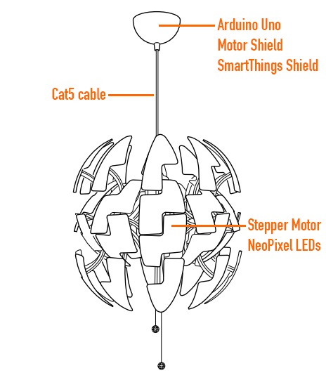
Ikea hacks are well widespread in the maker movement and David Bliss, founder at Nurun, did a great job transforming the Death Star inspired PS 2014 Pendant Lamp into something more dynamic.

The lamp was pimped up with an Arduino Uno and Arduino Motor Shield, NeoPixel LEDs and other components you can see in the illustration.

The detailed description of the project is on his blog , the code on github and the final result in the following video:

Arduino Blog 26 Nov 22:41
arduino  featured  ikea  led  motor  shield