Posts with «ultrasonic sensor» label

Parking Assistant Helps Back Up the Car Without Going Too Far

Sure, [Ty Palowski] could have just hung a tennis ball from the ceiling, but that would mean getting on a ladder, testing the studfinder on himself before locating a ceiling joist, and so on. Bo-ring. Now that he finally has a garage, he’s not going to fill it with junk, no! He’s going to park a big ol’ Jeep in it. Backwards.

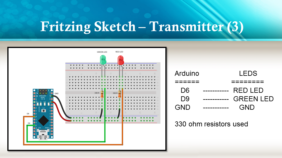
The previous owner was kind enough to leave a workbench in the rear of the garage, which [Ty] has already made his own. To make sure that he never hits the workbench while backing into the garage, [Ty] made an adorable stoplight to help gauge the distance to it. Green mean’s he’s good, yellow means he should be braking, and red of course means stop in the name of power tools.

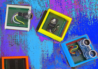
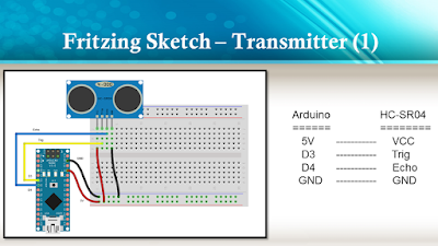
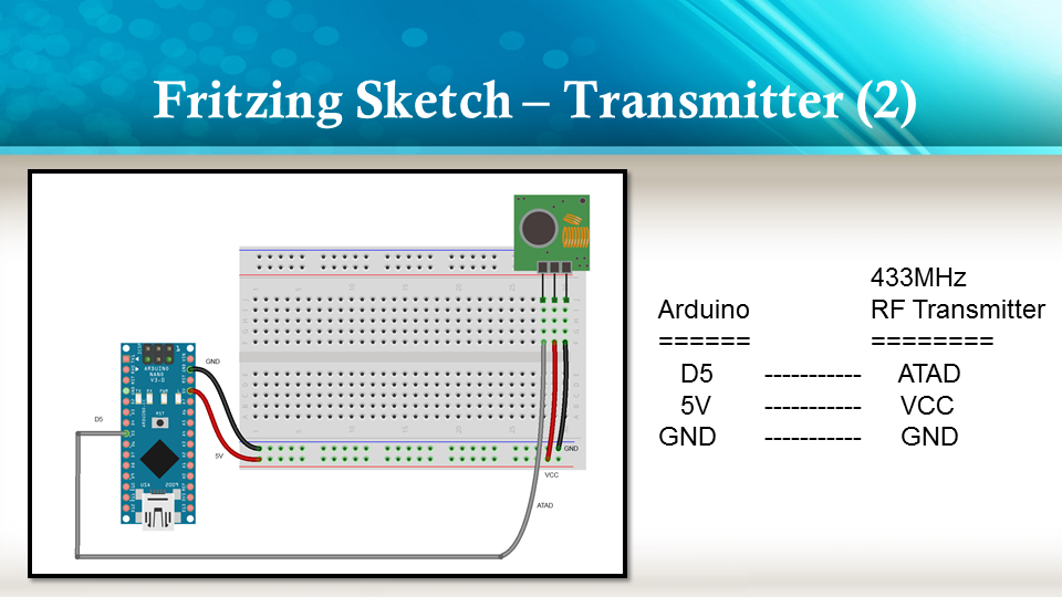
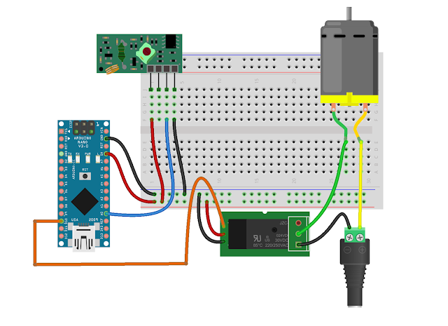
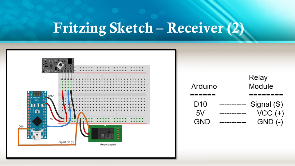
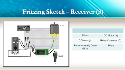
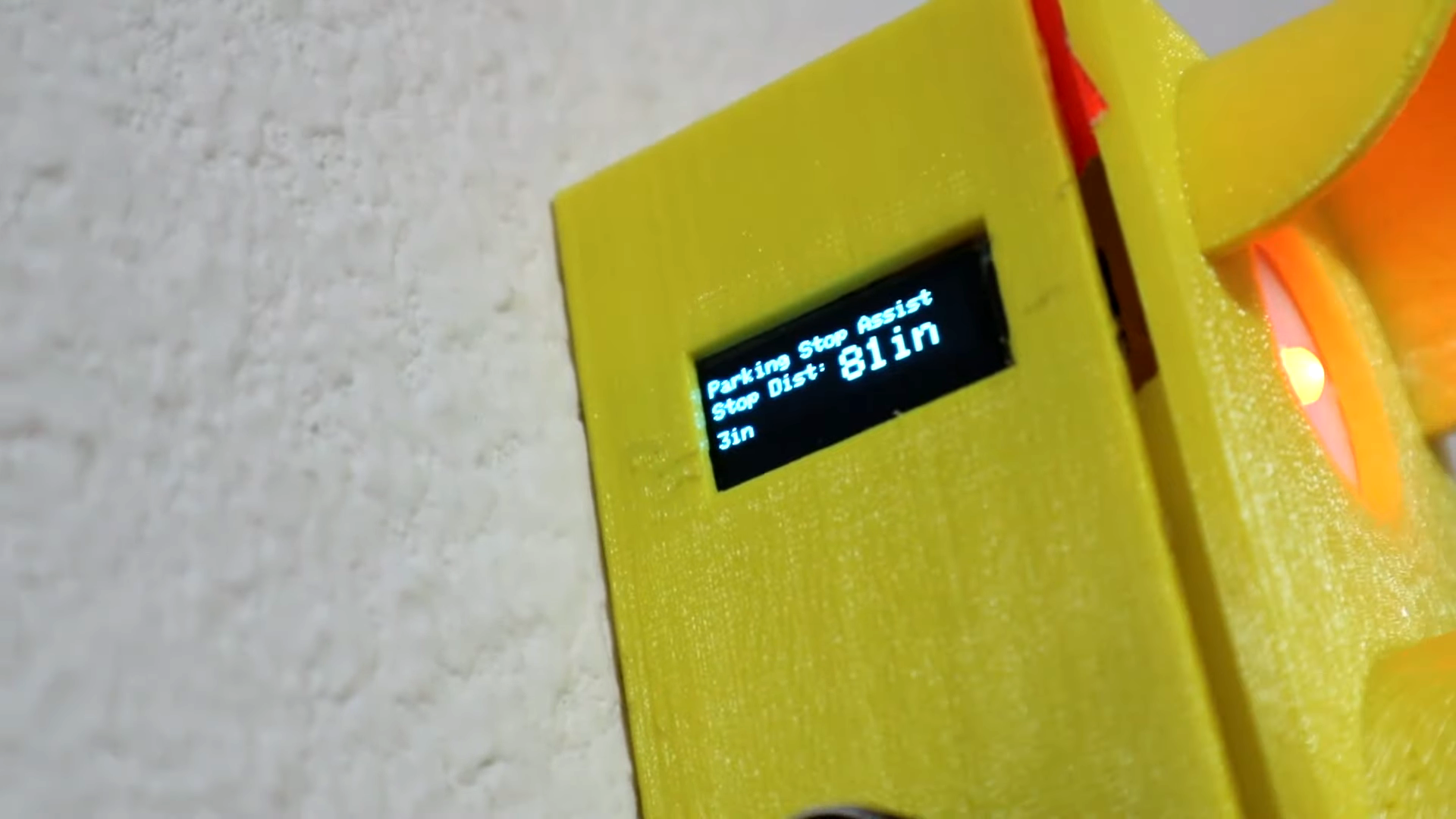
Inside the light is an Arduino Nano, which reads from the ultrasonic sensor mounted underneath the enclosure and lights up the appropriate LED depending on the car’s distance. All [Ty] has to do is set the distance that makes the red light come on, which he can do with the rotary encoder on the side and confirm on the OLED. The distance for yellow and green are automatically set from red — the yellow range begins 24″ past red, and green is another 48″ past yellow. Floor it past the break to watch the build video.

The humble North American traffic signal is widely recognized, so it’s a good approach for all kinds of applications. Teach your children well: start them young with a visual indicator of when it’s okay to get out of bed in the morning.

Ultrasonic Sensor Helps You Enforce Social Distancing

If you’re going outside (only for essential grocery runs, we hope) and you’re having trouble measuring the whole six feet apart from other people deal by eye, then [Guido Bonelli] has a solution for you. With a standard old HC-SR04 ultrasonic sensor, an audio module and a servo to drive a custom gauge needle he’s made a device which can warn people around you if they’re too close for comfort.

As simple as this project may sound like for anyone who has a bunch of these little Arduino-compatible modules lying around and has probably made something similar to this in their spare time, there’s one key component that gives it an extra bit of polish. [Guido] found out how intermittent the reliability of the ultrasonic sensor was and came up with a clever way to smooth out its output in order to get more accurate readings from it, using a bubble sort algorithm with a twist. Thirteen data points are collected from the sensor, then they are sorted in order to find a temporal middle point, and the three data points at the center of that sort get averaged into the final output. Maybe not necessarily something with scientific accuracy, but exactly the kind of workaround we expect around these parts!

Projects like these to help us enforce measures to slow the spread of the virus are probably a good bet to keep ourselves busy tinkering in our labs, like these sunglasses which help you remember not to touch your face. Make sure to check out this one in action after the break!

Measuring Airflow in an HVAC System

[Nubmian] wrote in to share his experiments with measuring airflow in an HVAC system. His first video deals with using with ultrasonic sensors. He found an interesting white paper that described measuring airflow with a single-path acoustic transit time flow meter. The question was, could he get the same effects with off-the-shelf components?

[Nubmian] created a rig using a pair of typical ultrasonic distance sensors. He detached the two transducers from the front of the PCB. The transducers were then extended on wires, with the “send” capsules together pointing at the “receive” capsules. [Nubmian] set the transducers up in a PVC pipe and blew air into it with a fan.

In his second video, [Nubmian] sets up a test rig consisting of a multimeter connected to an airflow sensor. The multimeter is soon replaced by an Arduino with the help of an AD623ARZ amp. The wires for that setup needed some shielding. Aluminum foil connected to the ground did the trick.

For more HVAC projects check out this pinwheel flow meter and [Adam]’s piece on HVAC techs, hackers who make house calls.


Filed under: home hacks

Prextron CHAIN BLOCKS - Arduino Nano controlled Ultrasonic sensor that switches a motor wirelessly using 433MHz RF modules and a relay board.


Description

In this tutorial, I will be evaluating Prextron CHAIN blocks – a new system that allows you to connect your sensors and actuators to an Arduino NANO using clever 3D-printed prototyping boards that can be stacked sideways. This very modular system makes it easy to connect, disconnect and replace project components, and eliminate the “rats nest of wires” common to many advanced Arduino projects. CHAIN BLOCKS are open, which means that you can incorporate any of your sensors or actuators to these prototyping boards, and you can decide which specific pin on Arduino you plan to use. The CHAIN BLOCK connections prevent or reduce common connection mistakes, which make them ideal for class-room projects and learning activities.

I am going to set up a project to put these CHAIN BLOCKs to the test:
When I place my hand in-front of an Ultrasonic sensor, the Arduino will transmit a signal wirelessly to another Arduino, and consequently turn on a motor.


Parts Required:

You need the following Prextron Chain Blocks


Please note: You may need to solder the module wires to the CHAIN BLOCK protoboard.


Arduino Libraries and IDE

This project does not use any libraries. However, you will need to upload Arduino code to the Arduino. For this you will need the Arduino IDE which can be obtained from the official Arduino website:
https://www.arduino.cc/en/main/software


ARDUINO CODE: RF Transmitter


ARDUINO CODE: RF Receiver


Fritzing diagrams for Transmitter


Fritzing diagrams for Receiver


Concluding comments

The purpose of this project was to evaluate Prextron CHAIN BLOCKs and put them to the test. Here is what I thought of CHAIN BLOCKS at the time of evaluation. Some of my points mentioned below may no longer apply to the current product. It may have evolved / improved since then. So please take that into consideration


What I liked about Chain Blocks

  • The design is simple, the product is simple.
  • Once the Chain Blocks were all assembled, they were very easy to connect to each other.
  • I can really see the benefit of Chain Blocks in a teaching environment, because it simplifies the connection process, and reduces connection mixups.
  • It was good to see that the blocks come in different colours, which means that you can set up different colour schemes for different types of modules.
  • You can incorporate pretty much any sensor or Actuator into the Chain block which is very appealing.
  • You also have the flexibility of choosing which pins you plan to use on the Arduino.
  • Projects look a lot neater, because you no longer have the rats nest of wires.
  • The Blocks lock into each other which means that they are much easier to transport/carry.


What I did not like about Chain Blocks

  • In most cases, the Chain Block protoboard lanes were not numbered, which increased the chances of making mistakes when soldering
  • The need to solder modules to the protoboard, may be a discouragement for some people.
  • I would have liked a choice of different size Chain blocks. Some of the sensors did not fit nicely into the Square blocks.
  • Prextron really need to work on their website if they plan to get serious with this product: Webpage has incomplete functionality or irrelevant links etc etc.


Thank you very much to Prextron for providing the CHAIN BLOCKS used in this tutorial, and allowing me to try out their product. If you are interested in trying them yourself, then make sure to visit them at:


If you like this page, please do me a favour and show your appreciation :

 
Visit my ArduinoBasics Google + page.
Follow me on Twitter by looking for ScottC @ArduinoBasics.
I can also be found on Pinterest and Instagram.
Have a look at my videos on my YouTube channel.


Blackboard digitization for under $40

Digital White/Black Boards or “Smart Boards” are very useful in modern classrooms, but their high cost often makes it difficult to convince administrators from loosening their purse strings. Cooper Union’s 2nd annual HackCooper event in New York wanted students to design and build hardware and software projects that both solve real problems and spark the imagination. At the 24 hour hackathon, the team of [harrison], [david] and [caleb] decided to put together a low-cost and simple solution to digitizing classroom black board content.

A chalk-holder is attached to two strings, each connected over a pulley to a weight. The weights slide inside PVC pipes at the two sides of the black board. Ultrasonic sensors at the bottom of each tube measure the distance to the weights. The weights sit in static equilibrium, so they serve the purpose of keeping the string taut without negatively interfering with the writer.

With a couple of calibration points to measure the extent of displacement of each weight, board width can be determined, making it easy to adapt to different sizes of boards. Once calibrated, the system can determine position of the chalk over the board based on some trigonometrical calculations. Since they had just 24 hours to hack the system together, they had to use a hand operated radio with a couple of buttons to provide user control. Pressing the “Write” button starts transmitting chalk movements to the digital screen. A second button on the radio remote serves to “Erase” the digital screen. After receiving the chalk position data, they had to do a fair amount of processing to eliminate noise and smooth out the writing on the digital screen.

A server allows the whole class to receive the chalk board data in real time. After each “Erase” command, the chalk board state is saved and logged on the server, thus allowing previous content to be viewed or downloaded. If only text is written, optical character recognition can be used to further digitize the content.

What makes the project really useful is the low cost. The sensors cost a dollar. The other parts – PVC pipe, weights/pulleys, Arduino and the Radio key fob – were all bought for under 40 dollars. For some additional cost (and maybe more time in their case) they could have automated the detection of when the chalk was actually doing the writing. The team have made their code available on Github. For a Chalk board at the other end of the cost spectrum, check this one out. Video below.


Filed under: Arduino Hacks

Lamp Comes to Life with Ultrasonic Sensors

Fans of the bouncing lamp from the Pixar corporate logo will enjoy [Daniel]‘s latest project. It’s a motion controlled desk lamp that uses ultrasonic sensors to control its physical position.

The core of the project is an Arduino and the three ultrasonic sensors. The sensors act as range finders, and when they are all working together under the direction of the microcontroller they can tell which direction a hand was moving when it passed by. This information is used to drive two servos, one in the base and one on the lamp’s arm.

The project requires an articulating desk lamp of some sort (others besides the specific one [Daniel] used shouldn’t be much of a problem as long as they bend in the same way). Most hackers will have the rest of the parts on hand, with the possible exception of the rangefinder. The code is up on the project site for a look-see or in case you want to build your own.

The only problem that [Daniel] had when putting this all together was that the base was a little wobbly. He was able to fix that with some thumbtacks, and we think the next step for the project should be switching the light on and off over the internet.


Filed under: home hacks

A Virtual Touchscreen (3D Ultrasonic Radar)

Producing items onto a screen simply by touching the air is a marvelous thing. One way to accomplish this involves four HC-SR04 ultrasonic sensor units that transmit data through an Arduino into a Linux computer. The end result is a virtual touchscreen that can made at home.

The software of this device was developed by [Anatoly] who translated hand gestures into actionable commands. The sensors attached to the Arduino had a an approximate scanning range of 3m, and the ultrasonic units were modified to broadcast an analog signal at 40 kHz. There were a few limitations with the original hardware design as [Anatoly] stated in the post. For example, at first, only one unit was transmitting at a time, so there was no way the Arduino could identify two objects on the same sphere. However, [Anatoly] updated the blog with a 2nd post showing that sensing multiple items at once could be done. Occasionally, the range would be finicky when dealing small items like pens. But besides that, it seemed to work pretty well.

Additional technical specifications can be found on [Anatoly]‘s blog and videos of the system working can be seen after the break.


[Thanks for the tip João!]


Filed under: Tech Hacks

My FirstMonster (or FM for short)

Primary image

What does it do?

autonomouse navigation

I managed to finish my first robot on witch I spent a lot of time, mostly because a lot of stuff was new to me. It is not very complicated but it seems to do it's job well. I posted everything about the build on my blog and also the parts I used (and the ones I rejected).

It is a Tamiya tracked platform with dual gearbox. I used an Arduino UNO and a SeeedStudio motor shield to drive it from a 11.7 lipo battery I had from my RC heli. It uses a Ultrasonic sensor to look in front and also a DIY IR sensor for backing up. I also added a temperature sensor for the fun of it.

Cost to build

$80,00

Embedded video

Finished project

Complete

Number

Time to build

20 hours

Type

tracks

URL to more information

Weight

300 grams

read more

Minecraft Creeper

Primary image

What does it do?

Obstacles avoidance via infrared sensor

Hello,

Greetings from Hong Kong.

This is my first Arduino project. I have worked with the handyboard and NXT few years ago. The Arduino seems popular and easy to get into for people from non-electronic background like me, so I decided to build something simple to get myself familiarize with the Arduino board and interfaces. For the look I decided to make it the Minecraft Creeper, for the non-gamers, it's a iconic mob that appears in the 8-bit inspired 3D game Minecraft. If you havent try it before, grab a copy now! 

Cost to build

$100,00

Embedded video

Finished project

Number

Time to build

Type

tracks

URL to more information

Weight

1500 grams

read more