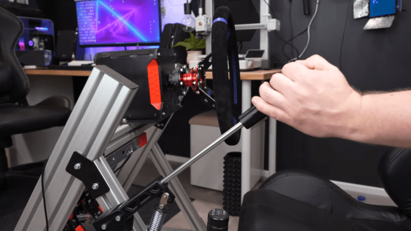
Simulator-style video games are designed to scale in complexity, allowing players to engage at anything from a casual level to highly detailed, realistic simulation. Microsoft Flight Simulator, for example, can be played with a keyboard and mouse, a controller, or a huge, expensive simulator designed to replicate a specific airplane in every detail. Driving simulators are similar, and [CNCDan] has been hard at work on his DIY immersive driving sim rig, with this hand brake as his latest addition.
For this build, [CNCDan] is going with a lever-style handbrake which is common in motorsports like drifting and rallying. He has already built a set of custom pedals, so this design borrows heavily from them. That means that the sensor is a load cell, which takes input force from a lever connected to it with a spring mechanism. The signal is sent to an Arduino for processing, which is set up to send data over USB like any joystick or controller. In this case, he’s using an Arduino that was already handling inputs from his custom shifter, so he only needed to use another input and add some code to get his handbrake added into his sim.
[CNCDan] built a version of this out of laser-cut metal parts, but also has a fully 3D printable one available as well. Plenty of his other videos about his driving rig are available as well, from the pedal assembly we mentioned earlier to the force-feedback steering wheel. It’s an impressive set of hardware with a feel that replicates racing about as faithfully as a simulator could. Interestingly, we’ve also seen this process in reverse as well where a real car was used instead as a video game controller.
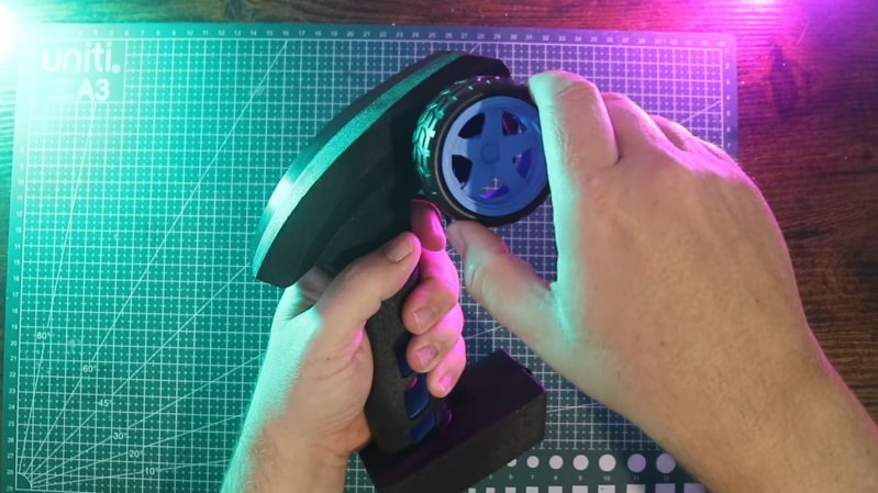
For a full-fledged, bells-and-whistles driving simulator a number of unique human interface devices are needed, from pedals and shifters to the steering wheel. These steering wheels often have force feedback, with a small motor inside that can provide resistance to a user’s input that feels the same way that a steering wheel on a real car would. Inexpensive or small joysticks often omit this feature, but [Jason] has figured out a way to bring this to even the smallest game controllers.
The mechanism at the center of his controller is a DC motor out of an inkjet printer. Inkjet printers have a lot of these motors paired with rotary encoders for precision control, which is exactly what is needed here. A rotary encoder can determine the precise position of the controller’s wheel, and the motor can provide an appropriate resistive force depending on what is going on in the game. The motors out of a printer aren’t plug-and-play, though. They also need an H-bridge so they can get driven in either direction, and the entire mechanism is connected to an Arduino in the base of the controller to easily communicate with a computer over USB.
In testing the controller does behave like its larger, more expensive cousins, providing feedback to the driver and showing that it’s ready for one’s racing game of choice. It’s an excellent project for those who are space-constrained or who like to game on the go, but if you have more space available you might also want to check out [Jason]’s larger version built from a power drill instead parts from an inkjet.
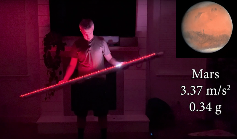
As Earthlings, most of us don’t spend a lot of extra time thinking about the gravity on our home planet. Instead, we go about our days only occasionally dropping things or tripping over furniture but largely attending to other matters of more consequence. When humans visit other worlds, though, there’s a lot more consideration of the gravity and its effects on how humans live and many different ways of training for going to places like the Moon or Mars. This gravity simulator, for example, lets anyone experience what it would be like to balance an object anywhere with different gravity from Earth’s.
The simulator itself largely consists of a row of about 60 NeoPixels, spread out in a line along a length of lightweight PVC pipe. They’re controlled by an Arduino Nano which has a built-in inertial measurement unit, allowing it to sense the angle the pipe is being held at as well as making determinations about its movement. A set of LEDs on the NeoPixel strip is illuminated, which simulates a ball being balanced on this pipe, and motion one way or the other will allow the ball to travel back and forth along its length. With the Earth gravity setting this is fairly intuitive but when the gravity simulation is turned up for heavier planets or turned down for lighter ones the experience changes dramatically. Most of the video explains the math behind determining the effects of a rolling ball in each of these environments, which is worth taking a look at on its own.
While the device obviously can’t change the mass or the force of gravity by pressing a button, it’s a unique way to experience and feel what a small part of existence on another world might be like. With enough budget available there are certainly other ways of providing training for other amounts of gravity like parabolic flights or buoyancy tanks, although one of the other more affordable ways of doing this for laypeople is this low-gravity acrobatic device.
Now, it’s been a shamefully long time since we’ve driven a car with a manual transmission, but as we recall it was pretty straightforward. It certainly didn’t require a lot of help with the shifting pattern, at least not enough to require a technical solution to know what gear you’re in. But then again, we suspect that’s not really the point of [upir]’s latest build.
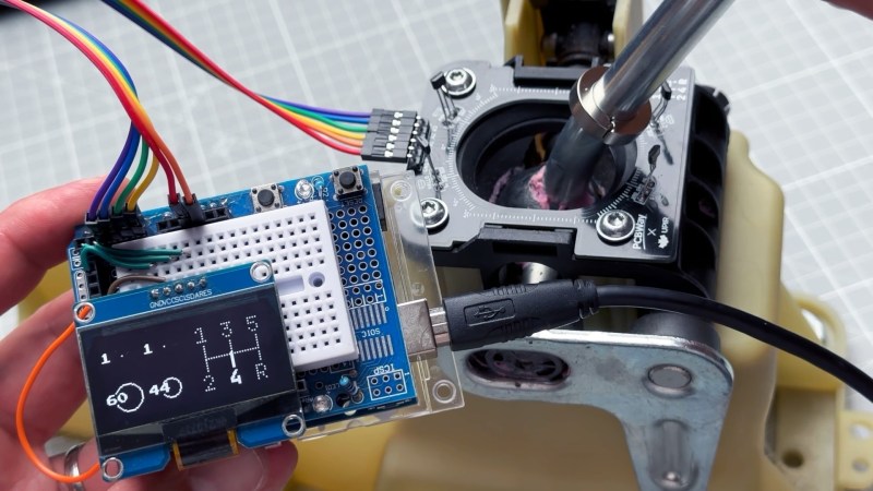
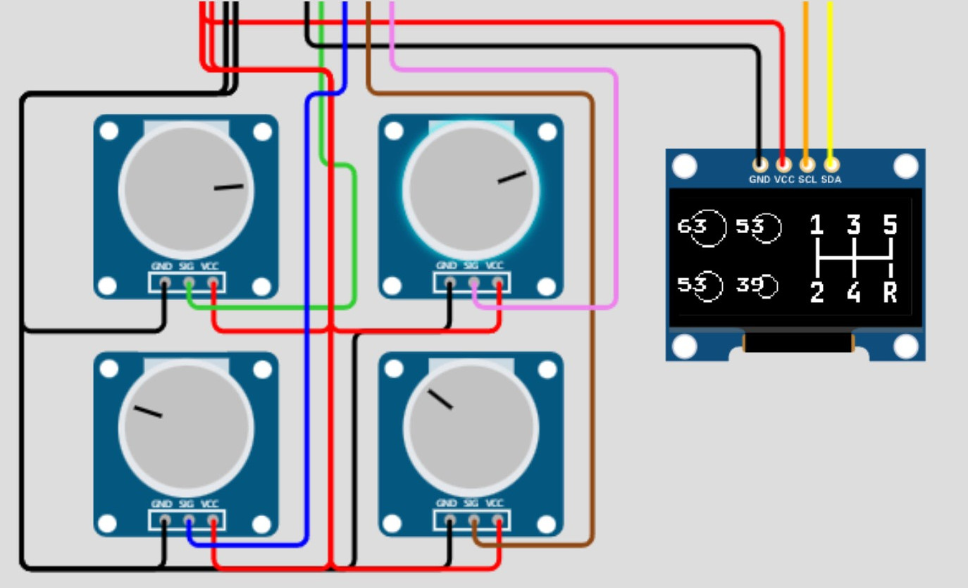
Oh sure, it’s pretty cool to display your current gear selection on a little LCD screen using an Arduino. And [upir] promises a follow-up project where the display goes inside the shifter knob, which will be really cool. But if you take a look at the video below, you’ll see that the real value of this project is the stepwise approach he takes to create this project. [upir] spends most of the time in the video below simulating the hardware and the code of the project in Wokwi, which lets him make changes and tune the design up before committing anything to actual hardware.
That turned out to be particularly useful with this build since he chose to use analog Hall sensors to detect the shift lever position and didn’t know exactly how that would work. Wokwi let him quickly build a virtual prototype for one sensor (using a potentiometer as a stand-in, since the simulator lacked a Hall sensor model), then quickly expand to the four sensors needed to detect all six gear positions.
By the time his simulation was complete, the code was almost entirely written. [upir] also walks us through his toolchains for both designing the graphics and laying out the PCB, a non-trivial task given the odd layout. We particularly enjoyed the tip on making smooth curved traces around the oval cutout for the shift lever in the board.
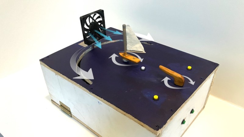
The ancient art of sailing can be very intimidating for the uninitiated given the shifty nature of wind. To help understand the interaction of wind direction and board orientation, [KifS] designed a hands-on sailing demonstrator that lets students grasp the basics before setting foot on a real sailboat.
The demonstrator uses a potentiometer as a tiller to control a model sailboat’s angle, while another stepper motor adjusts the position of a fan to simulate changing wind directions. With an Arduino Uno controlling everything, this setup affords students the opportunity to learn about sail positioning and adjusting to shifting winds in an interactive way, without the pressures and variables of being on the water.
[KifS]’s creation isn’t just about static demonstrations. It features four modes that progressively challenge learners—from simply getting a feel for the tiller, to adjusting sails with dynamic wind changes, even adding a game element that introduces random wind movements demanding quick adjustments. [KifS] mentions there are potentials aspects that can be refined, like more realistic sail response and usability, but it already achieved the main project goals.
It’s surprisingly easy to misjudge tips that come into the Hackaday tip line. After filtering out the omnipresent spam, a quick scan of tip titles will often form a quick impression that turns out to be completely wrong. Such was the case with a recent tip that seemed from the subject line to be a flight simulator cockpit. The mental picture I had was of a model cockpit hooked to Flight Simulator or some other off-the-shelf flying game, many of which we’ve seen over the years.
I couldn’t have been more wrong about the project that Grant Hobbs undertook. His cockpit simulator turned out to be so much more than what I thought, and after trading a few emails with him to get all the details, I felt like I had to share the series of hacks that led to the short video below and the story about how he somehow managed to build the set despite having no previous experience with the usual tools of the trade.
A Novel and a Film
Grant has been making short films for a while, mainly in collaboration with John Dwyer, an author of historical novels. Grant’s shorts are used as promos for John’s books, and nicely capture the period and settings of John’s novels. Most of these films required little in the way of special sets, relying instead on stock footage and vintage costumes to achieve their look and feel. John’s latest novel would change all that.
Called Mustang, the novel centers on a hotshot fighter pilot in WWII. Grant’s vision for the short to promote the book was inspired by the recent Christopher Nolan film Dunkirk, which featured intricate sequences filmed in the cockpit of a Spitfire. Granted wanted a similar look, and began arranging to use a real P-51 Mustang for filming. That presented immediate problems. First, there aren’t that many of the vintage aircraft left, and those that are still flying usually have anachronistic instruments in the cockpit, like GPS. Also, Grant wanted the instruments to respond as if the plane were airborne, and to have the shadows cast by the canopy into the cockpit suggest aerial maneuvers. Such an effect would be difficult to achieve with a plane stuck on a runway.
That’s when Grant realized that a gimballed cockpit simulator was needed. It could have a period-accurate dashboard, be positioned outdoors to take advantage of natural daylight and real backgrounds rather than CGI, and could be pitched, rolled and yawed to simulate flight. It would be perfect, and it would save the project. There was just one problem: he had no idea how to build it.
Helping Hands
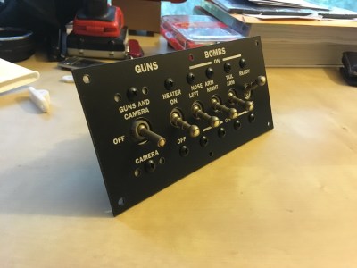
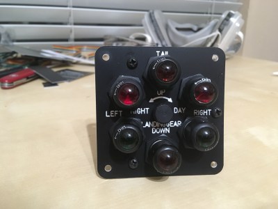
Wisely, Grant turned to his local hackerspace, Dallas Maker Space, for help. There he found not only the tools he lacked, but kindred spirits with the necessary skills and the willingness to share them. They started working on the cockpit instrument panel, which ended up including a combination of actual flight hardware and mocked-up instruments. The fake instruments used steppers and an Arduino to drive the needles, which were controlled by a custom iPad app that was used to animate them live during filming. The real instruments, like the artificial horizon and turn-and-slip indicator, were powered by a vacuum pump and responded to the movements of the simulator on its gimbals.
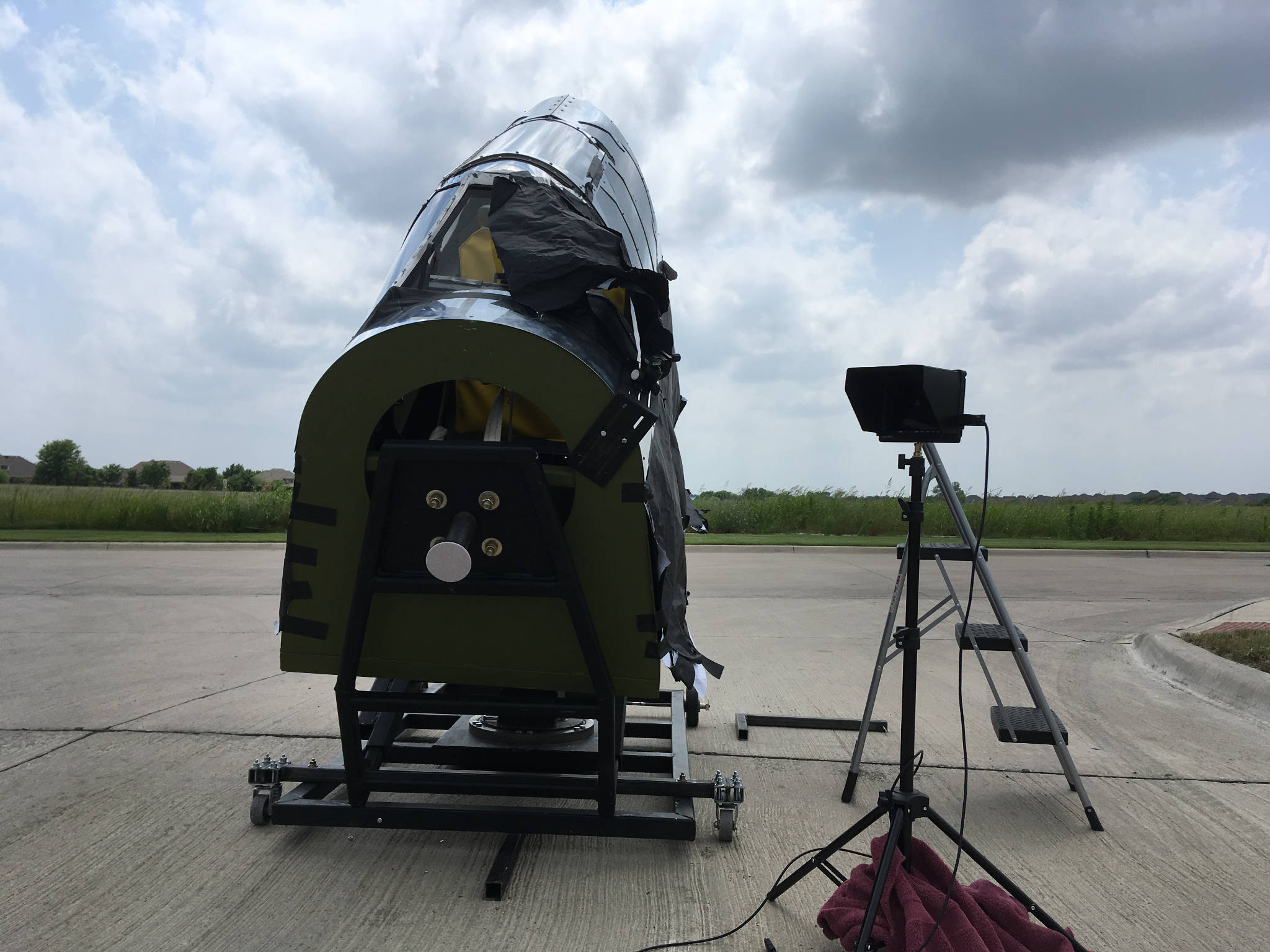
The gimballed cockpit set for exterior shots. The wide horizon and natural lighting combined with the 3-DOF gimbal make for a very realistic effect.
Mounting this convincing panel into something was an entirely different undertaking. Grant relied heavily on the experience of DMS members to design a structure strong enough to support the actor and allow for the motion needed to create a convincing effect. The cockpit mockup, made from plasma-cut sheet metal and plywood, is mounted to a heavy-duty three-axis gimbal, including a massive bearing from a pallet jack for the yaw axis.
Set and talent, ready for action.
Grant had originally planned to place the mockup on a mountaintop for shooting, much as the Spitfire mockup from Dunkirk was placed on the edge of a cliff to give an unobstructed horizon to simulate flying over the English Channel. When that proved logistically challenging, he set up on an airport runway and used clever camera blocking to avoid shooting the horizon. Grips manually moved the simulator while Grant manipulated the fake instruments and filmed the results, which I think speak for themselves. If only the budget – and on-set safety – would have supported simulating the massive four-blade Mustang propeller, the illusion would have been complete.
I really enjoyed digging into this project and all the hacks that it entailed. Movie magic is as much about hacking as anything else, at least behind the cameras, and it’s good to see what’s possible with a limited budget. We recently featured a low-budget but high-style sci-fi movie set build, and we’ve gone in-depth with a playback designer for the Netflix series Lost in Space, both in these pages and as a Hack Chat.
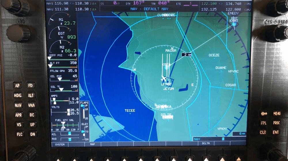
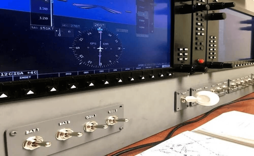
Apparently not satisfied to simulate flights on a single PC monitor, Ryan H came up with his own custom, 3D-printable cockpit setup for the Garmin G1000 avionics suite that uses a 12.1” LCD panel for flight data and a large number of additional inputs. The system is designed around the X-Plane 11 flight simulator, all controlled by an Arduino Mega with SimVim firmware.
The auxiliary display/inputs assemblies use the Arduino as an interface, enabling it to handle 32 tactile switches plus one standard and five dual rotary encoders via five CD74HC4067 16-channel multiplexers.
Have you ever looked around your city’s layout and thought you could do better? Maybe you’ve always wanted to see how she’d run on nuclear or wind power, or just play around with civic amenities and see how your choices affect the citizens.
[Robbe Nagel] made this physical-digital simulator for a Creative Programming class within an industrial design program. We don’t have all the details, but as [Robbe] explains in the video after the break, each block has a resistor on the bottom, and each cubbyhole has a pair of contacts ready to mate with it. An Arduino nestled safely in the LEGO bunker below reads the different resistance values to determine what block was placed where.
[Robbe] wrote a program that evaluates various layouts and provides statistics for things like population, overall health, education level, pollution, etc. As you can see after the break, these values change as soon as blocks are added or removed. Part of what makes this simulator so cool is that it could be used for serious purposes, or it could be totally gamified.
It’s no secret that we like LEGO, especially as an enclosure material. Dress it up or dress it down, just don’t leave any pieces on the floor.
Internals of 3D printed “print and fold” robot. [Image source: MIT CSAIL]Robot design traditionally separates the body geometry from the mechanics of the gait, but they both have a profound effect upon one another. What if you could play with both at once, and crank out useful prototypes cheaply using just about any old 3D printer? That’s where Interactive Robogami comes in. It’s a tool from MIT’s Computer Science and Artificial Intelligence Laboratory (CSAIL) that aims to let people design, simulate, and then build simple robots with a “3D print, then fold” approach. The idea behind the system is partly to take advantage of the rapid prototyping afforded by 3D printers, but mainly it’s to change how the design work is done.
To make a robot, the body geometry and limb design are all done and simulated in the Robogami tool, where different combinations can have a wild effect on locomotion. Once a design is chosen, the end result is a 3D printable flat pack which is then assembled into the final form with a power supply, Arduino, and servo motors.
A white paper is available online and a demonstration video is embedded below. It’s debatable whether these devices on their own qualify as “robots” since they have no sensors, but as a tool to quickly prototype robot body geometries and gaits it’s an excitingly clever idea.