Posts with «reviews» label

Review: OSEPP STEM Kit 1, a Beginner’s All-in-One Board Found in the Discount Aisle

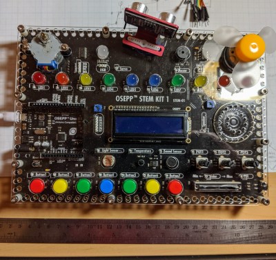
As the name implies, the OSEP STEM board is an embedded project board primarily aimed at education. You use jumper wires to connect components and a visual block coding language to make it go.

I have fond memories of kits from companies like Radio Shack that had dozens of parts on a board, with spring terminals to connect them with jumper wires. Advertised with clickbait titles like “200 in 1”, you’d get a book showing how to wire the parts to make a radio, or an alarm, or a light blinker, or whatever.

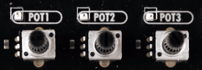
The STEM Kit 1 is sort of a modern arduino-powered version of these kits. The board hosts a stand-alone Arduino UNO clone (included with the kit) and also has a host of things you might want to hook to it. Things like the speakers and stepper motors have drivers on board so you can easily drive them from the arduino. You get a bunch of jumper wires to make the connections, too. Most things that need to be connected to something permanently (like ground) are prewired on the PCB. The other connections use a single pin. You can see this arrangement with the three rotary pots which have a single pin next to the label (“POT1”, etc.).
I’m a sucker for a sale, so when I saw a local store had OSEPP’s STEM board for about $30, I had to pick one up. The suggested price for these boards is $150, but most of the time I see them listed for about $100. At the deeply discounted price I couldn’t resist checking it out.

So does an embedded many-in-one project kit like this one live up to that legacy? I spent some time with the board. Bottom line, if you can find a deal on the price I think it’s worth it. At full price, perhaps not. Join me after the break as I walk through what the OSEPP has to offer.

What’s Onboard?

There are plenty of input and output devices:

  • 7 Push Buttons
  • Potentiometers (3 rotary and 1 slide)
  • Passive Infrared Sensor (PIR)
  • Light Sensor
  • Sound Sensor
  • LM35 Temperature Sensor
  • 10 LEDs (various colors)
  • Servo Motor
  • Stepper Motor
  • DC Motor
  • LCD Display
  • Buzzer
  • Speaker
  • RGB LED

In addition, the kit comes with an ultrasonic distance sensor in a little bracket that can connect to the stepper motor. That’s the only part that needs power and ground that isn’t already wired up.
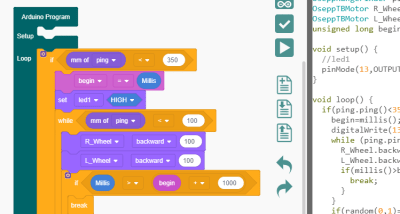
Because the heart of the board is an Arduino UNO clone, you can do anything you like to program it. However, OSEPP touts their visual block diagram language that is basically Scratch. You can use it for free on most platforms and there is even a Web-based version although it can’t download code. It looks like Scratch or other block-oriented systems you’ve seen before.

I’m not usually fond of the visual block languages, but this one at least shows you the actual Arduino code it generates, so that isn’t bad. But you can still use any other method you like such as the standard IDE or PlatformIO.

You can see a video about the board, below.

The Good and the Bad

The board feels substantial and able to withstand a good bit of abuse. There’s a good range of components, and I like that the arduino is a real daughter board and not just built onto the PCB. Despite using the block language, I do like the tutorial booklet. It is very slick and has projects ranging from an IR doorbell to a mini piano. You can see a page below — very colorful and clear.

Of course, the suggested retail price of $150 is a bit offputting. You might think a breadboard with a handful of LEDs and other parts would be a much lower-cost option but just look around for arduino kits for beginners and you’ll find prices are all over the place. On the other hand, with a parts kit you would have to know how to wire up things like stepper motors or DC motors, so there is some value to having it already done for you. There’s also value in not having a bag of parts to misplace.

The jumper wires in the kit have pins on one side and sockets on the other. The pins go into the Arduino’s connector and the sockets go over pins on the components. These aren’t quite as reliable as a spring clip and not as versatile either.

In my mind the worst part of the kit design is that the pins are right next to each of the components. That’s good for understanding, but it makes a mess of wiring. For instance, there are ten LEDs, and connecting them all means stretching jumper wires to both edges of the board The jumpers aren’t very long either, so any complex project is going to have wires crisscrossing the sensors and LCD.
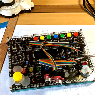
Granted, in this image I could have removed some of the wires from the bundles but that wouldn’t help that much, either. If you need to hook up more than a few of the available components you will have a mess. I would have put some sort of spring clip or even screw terminals and put them all on the top and bottom of the board with clear color-coded marking about where they connect. Then the wiring would all be out of the way. There are probably a few other ways they could have gone, and at this price, they could afford the few extra inches on the PCB.

There are a few other things that would have been nice touches to finish off this kit. I would have enjoyed a short chapter in the booklet about using the Arduino IDE directly so that people know it exists. And having even a small breadboard attached for your own exploration would make sense, but would then call for a different type of jumper wire.

Short Example Using the Distance Sensor

I wanted to do something with the board so I decided to play with the distance sensor and the servo. The distance sensor is a bit annoying both because you have to wire it all up and it has a tendency to fall off when you transport the board.

The demo (you can find it online) won’t win any originality prizes. The program moves the servo to scan from 0 to 180 degrees in 5 degree increments. It measures the distance of what’s in front of it. When it completes a scan, if it saw something close (you could adjust the sensitivity), it moves the sensor back to that position and waits 30 seconds. Otherwise, it keeps scanning.

Really, this is no different from any other Arduino program. That’s kind of the point. Despite the emphasis in the book on the point-and-click language, this is really just an Arduino.

In Summary

For the deep sale price I found, the board will work well for its intended audience of students or anyone starting out with Arduino or microcontrollers. Even a more advanced audience who just wants a way to hammer out a quick prototype might find it worth the $30 or $40 you can sometimes pay. But at full price, it is hard to imagine this makes sense because of the mess of wire routing and limited expansion options.

New Teensy 4.0 Blows Away Benchmarks, Implements Self-Recovery, Returns to Smaller Form

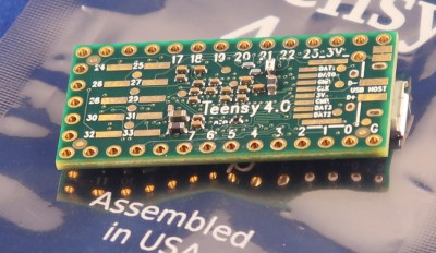
Paul Stoffregen did it again: the Teensy 4.0 has been released. The latest in the Teensy microcontroller development board line, the 4.0 returns to the smaller form-factor last seen with the 3.2, as opposed to the larger 3.5 and 3.6 boards.

Don’t let the smaller size fool you; the 4.0 is based on an ARM Cortex M7 running at 600 MHz (!), the fastest microcontroller you can get in 2019, and testing on real-world examples shows it executing code more than five times faster than the Teensy 3.6, and fifteen times faster than the Teensy 3.2. Of course, the new board is also packed with periperals, including two 480 Mbps USB ports, 3 digital audio interfaces, 3 CAN busses, and multiple SPI/I2C/serial interfaces backed with integrated FIFOs. Programming? Easy: there’s an add-on to the Arduino IDE called Teensyduino that “just works”. And it rings up at an MSRP of just $19.95; a welcomed price point, but not unexpected for a microcontroller breakout board.

The board launches today, but I had a chance to test drive a couple of them in one of the East Coast Hackaday labs over the past few days. So, let’s have a closer look.

First Impressions

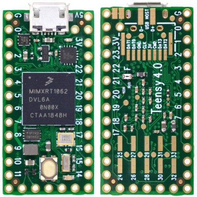
The board looks superficially similar to the older 3.2, at least from the top. There’s the usual dual row of pin headers you can plug into a breadboard, a micro-USB connector, and reset button. A new red LED near the USB connector gives you some status information, while the traditional “Arduino LED” is orange. Flip the board over, and you start to see some of the extra power this board wields. Besides ten more GPIO pins, there are pads for an SD card interface using 4-bit SDIO, and D+ and D- lines for the second 480 Mbps USB interface. The unmarked round pads are test points used in manufacturing and are no-connects from the end-user’s perspective.

Teensy 3.2 Everything Killer?

When doing hardware reviews it’s crucial to choose the right comparison hardware. I think the best comparison in this case is between the two boards that share the same form factor; the Teensy 4.0 and the 3.2. I’ve chosen not to make the comparison with the Teensy 3.5 and 3.6, which are priced a little higher, in a larger form factor, and have SD card slots soldered on.

Incredibly, the Teensy 4.0 is priced at $19.95, as opposed to the $19.80 Teensy 3.2. What does that extra fifteen cents buy? First, there’s performance. The 4.0’s 600 MHz clock vs the 72 MHz on the 3.2 doesn’t tell the whole story. The Cortex M7 on the 4.0 is a dual-issue superscalar processor capable of executing up to two 32-bit instructions per clock cycle; initial tests showed this happening between 40-50% of the time on Arduino-compiled code. Additionally, the Cortex-M7 is the first ARM microcontroller with branch prediction. While on the Cortex M4, a branch always takes 3 clock cycles, after a few passes through a loop, for instance, the Cortex M7 can begin executing correctly-predicted branches in a single clock. This is technology originally pioneered in supercomputers that you can use in your next Halloween costume.
Then, there’s floating-point. Veteran embedded programmers may have a bias against floating-point code, and with good reason. Without native floating-point instructions, these operations must be emulated, and run very slowly. The same thing happens with double-precision operations on a processor which only supports single-precision instructions. While Cortex-M4 processors support single-precision floating-point, the Cortex-M7’s include native double-precision instructions, so if you need the extra precision afforded by doubles, you’re not going to take a huge performance hit: basically, doubles seem to execute in only twice as many cycles as floats.

The Cortex-M7 on this board also supports tightly-coupled memory (TCM), which provides fast access like a cache, but without the non-determinism that can complicate hard real-time applications — one of the problems with other high-power microcontrollers. The 64-bit ITCM bus can fetch 64-bits, while two dedicated 32-bit buses (DTCM) can fetch up to two instructions from the TCM each cycle – these buses are separate from the main AXI bus used to communicate with other memory and peripherals. The Teensyduino environment automatically allocates code and statically allocated memory into the DTCM area, which can be up to 512K in size, although you can override the default behavior with some command-line switches. Memory that isn’t accessed by the tightly-coupled buses is optimized for access by the peripherals using DMA.

Spec Sheet

Despite its size, there’s a lot to this board and the chip it carries, so here’s condensed spec list:

  • ARM Cortex-M7 at 600 MHz
  • 1024K RAM (512K is tightly coupled)
  • 2048K Flash (64K reserved for recovery & EEPROM emulation)
  • 2 USB ports, both 480 MBit/sec
  • 3 CAN Bus (1 with CAN FD)
  • 2 I2S Digital Audio
  • 1 S/PDIF Digital Audio
  • 1 SDIO (4 bit) native SD
  • 3 SPI, all with 16 word FIFO
  • 3 I2C, all with 4 byte FIFO
  • 7 Serial, all with 4 byte FIFO
  • 32 general purpose DMA channels
  • 31 PWM pins
  • 40 digital pins, all interrupt capable
  • 14 analog pins, 2 ADCs on chip
  • Cryptographic Acceleration
  • Random Number Generator
  • RTC for date/time
  • Programmable FlexIO
  • Pixel Processing Pipeline
  • Peripheral cross triggering
  • Power On/Off management

The board consumes around 100 mA with a 600 MHz clock. Although I didn’t try it myself with the evaluation boards I have here, Paul notes that it can be overclocked for a performance boost. It also supports dynamic clock scaling: the instruction clock speed is decoupled from the peripherals, so that baud rates, audio sample rates, and timing functions continue to function properly if you change the CPU speed.

For the ultimate in power savings, you can shut the board off by adding a pushbutton to the On/Off pin. Pressing the button for more than five seconds disables the 3.3 V supply; a subsequent brief press will turn it back on. This doesn’t affect the real-time-clock (RTC) functionality, however: connecting a coin cell to the VBAT terminal will keep the time and date counter going.

Hands-On Benchmarks

Higher is better
Board CoreMark
Teensy 4.0 2313.57
Teensy 3.6 440.72
Sparkfun ESP32 Thing 351.33
Teensy 3.5 265.50
Teensy 3.2 218.26
Metro M4 Grand Central 214.85
Arduino Due 94.95
Arduino Zero 56.86
Arduino Mega 7.03

To see how fast this thing really is, Paul ported the CoreMark embedded-processor benchmark to the Arduino environment. (Note that CoreMark seems to be a registered trademark of the Embedded Microprocessor Benchmark Consortium (EEMBC)). This synthetic benchmark tests performance managing linked lists, doing matrix multiplies, and executing state machine code. He reports the following scores for a number of boards (larger numbers are better).

I was able to verify the Teensy 4.0 and 3.2 numbers; my 3.6 must have sprouted legs and walked off somewhere, and I didn’t have any of the other boards handy for testing. Using my numbers (nearly identical to those above), the 4.0 is around ten times as fast as the 3.2.

Since the CoreMark code is a “synthetic” benchmark, Paul wanted to test the new board in a more realistic scenario. In another GitHub repo, he has some code to do an RSA signature with a 2048-bit key. This is a processor-intensive operation, believe me — I had to implement it once in Lua (don’t ask!). Here are the scores for the same boards (lower numbers are better).

Lower is better
Board Seconds
Teensy 4.0 0.085
Teensy 3.6 0.474
Sparkfun ESP32 Thing 0.518
Metro M4 Grand Central 0.840
Teensy 3.5 0.909
Teensy 3.2 1.325
Arduino Due 1.901
Arduino Zero 9.638

Again, I was able to verify the numbers for the Teensy 3.2 and 4.0 boards. In this case, the 4.0 is around fifteen times as fast as the 3.2.

If you have any of these, or other Arduino-compatible boards lying around, clone one or both of these repos, open the respective *.ino file from either one, and test them out. Feel free to report results in the comments below.

15 Seconds to Sanity

One of the new features of the Teensy 4.0 is the automatic recovery process, which restores the board to a known good state without the need for a PC connection. If you press and hold the reset button for 15 seconds, the red LED will flash to indicate you’ve entered restore mode. Once you release the button, the red LED will illuminate while the flash memory is erased and re-written with the traditional Arduino “blink” program. Once the re-write is complete, the blink program is run and the orange LED begins blinking, just like on every Arduino-compatible for the past decade and a half. It’s DFU mode without the need for host computer or known-working binary. These used to be key components for hardware-based restore and now they’re part of the board itself.

Why would you want to do this? In a nutshell, because USB itself is a train-wreck. On top of an insanely sprawling and complex protocol, there are charge-only cables sans data pins lurking in your junk box, operating system bugs waiting to trip you up (looking at you, Windows 7), and a whole host of other issues that cause serious head-scratching when things stop working. This can be especially confusing with native-USB boards like the Teensy 4.0; while the built-in USB functionality is amazingly powerful, and can be used in a wide variety of ways, when something stops working, you’re not always sure how to get back on track. Now, you are – just press the button.

What Can You Do with a 600 MHz Microcontroller?

Paul envisions this Teensy 4.0 being used for polyphonic audio synthesis, running moderately complex machine learning algorithms, and real-time audio analysis. In many cases, the first level of processing on data-intensive input devices can now be moved from a host computer to the external microcontroller, narrowing the bandwidth required to the host system. And for projects driving a display, the built-in pixel processing pipeline can also accelerate graphics operations, offloading this work from the CPU.

There will be some fraction of hackers that will still wonder why we need a 600 MHz microcontroller; another fraction will have already needed it yesterday. In between, most users will take some time to figure out what doors this opens up. The reality is that our tools constrain not only our current designs, but also, to some extent, our imagination. A 15x performance improvement over the current tiny development board you may be using could enable some new and exciting applications, and you, dear reader, are the one who makes them happen. So, drive home a different way from work tonight, sleep on the sofa instead of the bed, or use whatever other tricks you have to shock your brain into creativity and figure out what you could really do with this thing. It’s a lot more than you can do with a 555. For that matter, it’s a lot more than most computers could do in the 90s.

Malduino Elite – First Impressions

A while back, I wrote an article about Malduino, an Arduino-based, open-source BadUSB device. I found the project interesting so I signed up for an Elite version and sure enough, the friendly postman dropped it off in my mail box last Friday, which means I got to play around with it over the weekend. For those who missed the article, Malduino is USB device which is able to emulate a keyboard and inject keystrokes, among other things. When in a proper casing, it will just look like a USB flash drive. It’s like those things you see in the movies where a guy plugs in a device and it auto hacks the computer. It ships in two versions, Lite and Elite, both based on the ATmega32U4.

The Lite version is really small, besides the USB connector it only contains a switch, which allows the user to choose between running and programming mode, and a LED, which indicates when the script has finished running.

Original Malduino Elite sketch and Lite prototype

The Elite version is bigger, comes with a Micro-SD card reader and four DIP switches, which allow the user to choose which script to run from the card. It also has the LED, which indicates when a script has finished to run. This allows the user to burn the firmware only once and then program the keystroke injection scripts that stored in the Micro-SD card, in contrast to the Lite version which needs to be flashed each time a user wants to run a different script.

These are the two Malduinos and because they are programmed straight from the Arduino IDE, every feature I just mentioned can be re-programmed, re-purposed or dropped all together. You can buy one and just choose to use it like a ‘normal’ Arduino, although there are not a lot of pins to play around with. This freedom was one the first things I liked about it and actually drove me to participate in the crowd-funding campaign. Read on for the full review.

The Hardware

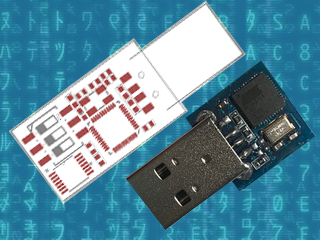
Malduino Elite vs USB flash drive

So the Elite board arrived as schedule and I found myself some time to look an it. Despite being longer than the Lite version, it’s still quite small, measuring roughly 4.6 cm x 1.1 cm (around 1.8 in x 0.43 in), which you can easily adapt to an old USB case, although you’ll have to cut some holes for the DIP switches and the Micro-SD card. In the crowd-funding campaign, the original sketch was for a 3 DIP switch version but the final Elite has four, which I found nice. I plugged it in to an old computer, after some consideration about which firmware it could ship with and what it could do to my laptop, and sure enough a red LED appeared. And that was it. Nothing else.

After playing around with the switches and exercising some RTFM, I realised that the firmware it ships with is probably some sort of Q.C. test for the dips, which makes the Malduino output the numbers 1 to 4 (actually simulating a keypress 1 to 4), depending on which switches are ON. So far so good, it works and I’ve seen worse PCB boards than this one. The board has holes for six pins, which I did not trace to the micro-controller and I don’t know what they are for.

The Setup

Setting up the Malduino requires that you have the Arduino IDE installed and up to date. You’ll need to open up the board manager and install the Sparkfun boards since the Elite is programmed as a ‘Sparkfun Pro Micro’ running at 3.3 V and 8 MHz. Then you need to go the Malduino Script Converter website which serves several purposes:

  • It allows to convert scripts between the Lite and Elite versions
  • It allows you to choose your keyboard layout language
  • It auto generates the Arduino project for you to import to the IDE

For the Elite version, just create a simple or even empty script to download the project, since when in ‘normal’ operation you will just flash the Malduino once and then use the Micro-SD card to store new scripts.

A note on flashing, if you are using a Debian-based distribution you might come across some problems like I did and not be able to flash the device. Like the user on this most useful post, my modem-manager was trying to talk with the Malduino after every reset and confused AVRDUDE to death. The solution is to add udev rules to “/etc/udev/rules.d/77-mm-usb-device-blacklist-local.rules”, kudos to [socrim]:

ACTION!="add|change", GOTO="mm_usb_device_blacklist_local_end"
SUBSYSTEM!="usb", GOTO="mm_usb_device_blacklist_local_end"
ENV{DEVTYPE}!="usb_device", GOTO="mm_usb_device_blacklist_local_end"

ATTRS{idVendor}=="1b4f" ATTRS{idProduct}=="9204", ENV{ID_MM_DEVICE_IGNORE}="1"
ATTRS{idVendor}=="1b4f" ATTRS{idProduct}=="9203", ENV{ID_MM_DEVICE_IGNORE}="1"

LABEL="mm_usb_device_blacklist_local_end"

The Software

Since I’m running Linux, a quick shortcut to run a command is the ALT-F2 combination. So I script that into a file and save it to 1111.txt. The Elite searches the Micro-SD card for a file corresponding to the current dip switch state. Lets say the dip switch 2 and 4 are ON. In this case, the software tries to find the file named 0101.txt and parse its contents (as in dip switch order 1,2,3,4 and not the binary representation of the number 2 and 4) . When it finishes, the red LED starts flashing quickly. My simple script was:

DELAY 2000
ALT F2
DELAY 1000
STRING xterm
DELAY 1000
ENTER
DELAY 1000
STRING id
DELAY 1000
ENTER

But it was not working. Almost all commands worked but the ALT-F2 combo was not functioning properly. Close, but no cigar. No ALT-F2, no run command window. I’ve already lazy-browsed the source code a bit because I really didn’t have a lot of time on my hands but I needed to figure this out. The offending code was this:

else if(equals(s,e,"F1",<strong>3</strong>)) Keyboard.press(KEY_F1);</pre>

else if(equals(s,e,"F2",<strong>3</strong>)) Keyboard.press(KEY_F2);
...
else if(equals(s,e,"F10",3)) Keyboard.press(KEY_F10);
else if(equals(s,e,"F11",3)) Keyboard.press(KEY_F11);

A custom equals function was receiving size 3 for the strings of the Function keys, like “F2”. It was ok for “F10”, “F11” and “F12”, but failed for the rest of the keys. Changing 3 to 2 did the trick, but my Portuguese keyboard layout started to interfere with other test scripts. So I changed the code to include PT and UK layouts, changing them in a #define at compile time.

It would be cool if it was possible to access the SD card from the computer as a regular USB volume. I don’t know exactly how feasible that is, but it does not come with the current firmware. I still wanted to be able to output the content of an arbitrary file on the SD card to the screen, so I added another script function called ECHOFILEHEX that outputs the content of a file in the SD card as escape characters. For example, if the file a.txt contains “AAA”, the script command ECHOFILEHEX a.txt would output “\x41\x41\x41”. This can be useful to echo binary files into printf or echo -e, in Linux hosts at least.

Meanwhile, I had some trouble reading the original code. You know, we all have different programming styles. Don’t get me wrong, I’ve been known to write some messed-up spaghetti code. I sometimes browse old projects looking for some libs or classes I coded and wonder ‘who the heck wrote this steaming pile of code?’ Me, it was me. Anyway, I started to change a bit here and there and ended up changing pretty much the entire code. That’s the beauty and the curse of open-source. If you’re curious you can check it out here.

Conclusion

All in all, and despite some bumps, I’m quite pleased with Malduino. It is what I expected: an open platform for BadUSB attacks that’s in its infancy. It’s awesome that we can all tinker with it, modify it, make it better or just make it suit our needs. I hope a real community can start so we can see its full potential emerge. My short list includes simulating other USB devices, better SD card management, and expanding the device via the unused pins. What would you add?

It’s a long way to go and a lot can go wrong, so good luck with the project [Seytonic]!


Filed under: Featured, reviews, security hacks

From the New Issue of Make: Our 8 Standout Dev Boards

These eight boards stand out for their advanced specs, built-in offerings, and, in some cases, their innovative interface options.

Read more on MAKE

The post From the New Issue of Make: Our 8 Standout Dev Boards appeared first on Make: DIY Projects and Ideas for Makers.

First Look at ABC: Basic Connections

[Alberto Piganti], aka [pighixxx] has been making circuit diagram art for a few years now, and has just come out with a book that’s available on Kickstarter. He sent us a copy to review, and we spent an hour or so with a refreshing beverage and a binder full of beautiful circuit diagrams. It doesn’t get better than that!

[pighixxx] started out making very pretty and functional pinout diagrams for a number of microcontrollers, and then branched out to modules and development boards like the Arduino and ESP8266. They’re great, and we’ll admit to having a printout of his SMD ATMega328 and the ESP-12 on our wall. His graphical style has been widely copied, which truly is the sincerest form of flattery.

But after pinouts, what’s next? Fully elaborated circuit diagrams, done in the same style, of course. “ABC: Basic Connections” started out life as a compendium of frequently used sub-circuits in Arduino projects. But you can take “Arduino” with a grain of salt — these are all useful for generic microcontroller-based projects. So whether you want to drive a 12 V solenoid from a low-voltage microcontroller, drive many LEDs with shift registers, or decode a rotary encoder, there is a circuit snippet here for you.

One of the things that we like most about the graphics in “ABC” is that they’re not dumbed down — they’re fundamentally just well-done circuit diagrams, but with graphic touches and extra detail where it actually helps to clarify things. This is a middle ground between the kind of schematic you use in a PCB layout program and the kind of diagram you get from Fritzing. In the former, every part has a symbol but multifunction parts like microcontrollers are just represented as squares bristling with pin numbers. In the latter, wiring up an IC is easy because the parts and pins are represented graphically, but you quickly run out of colors for the different wires, and the “breadboard” turns into a rat’s nest with a circuit of any complexity.

“ABC” takes the middle road, using standard circuit diagram style overall, but also the nice graphic representations of the ICs and modules that [pighixxx] is good at. Is a 2N2222 pinned EBC or BCE? You don’t have to look that up, because it’s sketched out for you here. We’d guess that this attractive, but information-rich, style is a great fit for the target audience — people with some electronics experience who do not yet have their favorite transistor symbol tattooed on their forearm. [pighixxx]’s diagrams are simple, easy to understand, easy to use, and pretty to boot.

There is a planned online counterpart to the book, with further elaborations of all of the circuit setups. They’re not finished yet, but they have a lot more of the flavor of the Fritzing-style, this-wire-goes-to-that-hole diagrams. This style does work better in an online format than in a physical book, because you can build up the rat’s nest in bite-sized steps, none of which are too overwhelming. But honestly, for an advanced beginner or intermediate electronics hacker, the book can be treated as stand-alone. The web content may help the rank newbie when they get stuck.

Tee-hee.

The breadth of circuits in “ABC” is fairly wide, covering most of the microcontroller-interfacing problems that we’ve ever encountered. None of the circuits are revolutionary — they’re the tried-and-true, correct solutions to the various problems, rather than anything too hacky or clever. We weren’t surprised by any of the circuits, but we didn’t find anything that we wouldn’t use ourselves either. These are basic connections after all, and a darn solid collection of them.

To sum up, “ABC” is an attractive book in a handy binder format that would make a great collection of solutions for anyone who’s just getting started in the whole “Arduino” scene but who gets hung up on interfacing the chips with the real world. It’s a handy reference for the pinouts of a number of frequently used parts, combined with the resistors, flyback diodes, level-shifting circuits, and whatever else that you’d need to make them work. It’s what we wish our simple circuit diagrams looked like. We like it.


Filed under: Hackaday Columns, reviews

PlatformIO and Visual Studio Take over the World

In a recent post, I talked about using the “Blue Pill” STM32 module with the Arduino IDE. I’m not a big fan of the Arduino IDE, but I will admit it is simple to use which makes it good for simple things.

I’m not a big fan of integrated development environments (IDE), in general. I’ve used plenty of them, especially when they are tightly tied to the tool I’m trying to use at the time. But when I’m not doing anything special, I tend to just write my code in emacs. Thinking about it, I suppose I really don’t mind an IDE if it has tools that actually help me. But if it is just a text editor and launches a few commands, I can do that from emacs or another editor of my choice. The chances that your favorite IDE is going to have as much editing capability and customization as emacs are close to zero. Even if you don’t like emacs, why learn another editor if there isn’t a clear benefit in doing so?

There are ways, of course, to use other tools with the Arduino and other frameworks and I decided to start looking at them. After all, how hard can it be to build Arduino code? If you want to jump straight to the punch line, you can check out the video, below.

Turns Out…

It turns out, the Arduino IDE does a lot more than providing a bare-bones editor and launching a few command line tools. It also manages a very convoluted build process. The build process joins a lot of your files together, adds headers based on what it thinks you are doing, and generally compiles one big file, unless you’ve expressly included .cpp or .c files in your build.

That means just copying your normal Arduino code (I hate to say sketch) doesn’t give you anything you can build with a normal compiler. While there are plenty of makefile-based solutions, there’s also a tool called PlatformIO that purports to be a general-purpose solution for building on lots of embedded platforms, including Arduino.

About PlatformIO

Although PlatformIO claims to be an IDE, it really is a plugin for the open source Atom editor. However, it also has plugins for a lot of other IDEs. Interestingly enough, it even supports emacs. I know not everyone appreciates emacs, so I decided to investigate some of the other options. I’m not talking about VIM, either.

I wound up experimenting with two IDEs: Atom and Microsoft Visual Studio Code. Since PlatformIO has their 2.0 version in preview, I decided to try it. You might be surprised that I’m using Microsoft’s Code tool. Surprisingly, it runs on Linux and supports many things through plugins, including an Arduino module and, of course, PlatformIO. It is even available as source under an MIT license. The two editors actually look a lot alike, as you can see.

PlatformIO supports a staggering number of boards ranging from Arduino to ESP82666 to mBed boards to Raspberry Pi. It also supports different frameworks and IDEs. If you are like me and just like to be at the command line, you can use PlatformIO Core which is command line-driven.

In fact, that’s one of the things you first notice about PlatformIO is that it can’t decide if it is a GUI tool or a command line tool. I suspect some of that is in the IDE choice, too. For example, with Code, you have to run the projection initialization tool in a shell prompt. Granted, you can open a shell inside Code, but it is still a command line. Even on the PlatformIO IDE (actually, Atom), changing the Blue Pill framework from Arduino to mBed requires opening an INI file and changing it. Setting the upload path for an FRDM-KL46 required the same sort of change.

Is it Easy?

Don’t get me wrong. I personally don’t mind editing a file or issuing a command from a prompt. However, it seems like this kind of tool will mostly appeal to someone who does. I like that the command line tools exist. But it does make it seem odd when some changes are done in a GUI and some are done from the command line.

That’s fixable, of course. However, I do have another complaint that I feel bad for voicing because I don’t have a better solution. PlatformIO does too much. In theory, that’s the strength of it. I can write my code and not care how the mBed libraries or written or the Arduino tools munge my source code. I don’t even have to set up a tool chain because PlatformIO downloads everything I need the first time I use it.

When that works it is really great. The problem is when it doesn’t. For example, on the older version of PlatformIO, I had trouble getting the mBed libraries to build for a different target. I dug around and found the issue but it wasn’t easy. Had I built the toolchain and been in control of the process, I would have known better how to troubleshoot.

In the end, too, you will have to troubleshoot. PlatformIO aims at moving targets. Every time the Arduino IDE or the mBed frameworks or anything else changes, there is a good chance it will break something. When it does, you are going to have to work to fix it until the developers fix it for you. If you can do that, it is a cost in time. But I suspect the people who will be most interested in PlatformIO will be least able to fix it when it breaks.

Bottom Line

If you want to experiment with a different way of building programs — and more importantly, a single way to create and build — you should give PlatformIO a spin. When it works, it works well. Here are a few links to get you started:

Bottom line, when it works, it works great. When it doesn’t it is painful. Should you use it? It is handy, there’s no doubt about that. The integration with Code is pretty minimal. The Atom integration — while not perfect — is much more seamless. However, if you learn to use the command line tools, it almost doesn’t matter. Use whatever editor you like, and I do like that. If you do use it, just hope it doesn’t break and maybe have a backup plan if it does.


Filed under: Arduino Hacks, ARM, Hackaday Columns, reviews, Skills

Hands On With The First Open Source Microcontroller

2016 was a great year for Open Hardware. The Open Source Hardware Association released their certification program, and late in the year, a few silicon wizards met in Mountain View to show off the latest happenings in the RISC-V instruction set architecture.

The RISC-V ISA is completely unlike any other computer architecture. Nearly every other chip you’ll find out there, from the 8051s in embedded controllers, 6502s found in millions of toys, to AVR, PIC, and whatever Intel is working on are closed-source designs. You cannot study these chips, you cannot manufacture these chips, and if you want to use one of these chips, your list of suppliers is dependent on who has a licensing agreement with who.

We’ve seen a lot of RISC-V stuff in recent months, from OnChip’s Open-V, and now the HiFive 1 from SiFive. The folks at SiFive offered to give me a look at the HiFive 1, so here it is, the first hands-on with the first Open Hardware microcontroller.

Before I dig into this, I must discuss the openness of the HiFive 1, and RISC-V in general. Free Software and Open Hardware is a religion, and it’s significantly more difficult to produce Open Hardware than Free Software. No matter how good or how Open the design is, the production of the first Open Source microcontroller will generate far too many comments from people who use the words ‘moral imperative’ while citing utilitarian examples of why Open and Libre is good. You should ignore these comments, but not just because these people have only read the back cover of the Cliff’s Notes for Philosophy For Dummies.

The Openness of the HiFive 1 and RISC-V

The biggest selling point for RISC-V chips is that there are no licensing fees, and this microcontroller is Open Source. This is huge — your AVRs, PICs, ARMs, and every other microcontroller on the planet is closed hardware. You can’t study the silicon. If we’re ever going to get a completely Open Source computer, it has to start somewhere, and here it is.

With that said, this is an Arduino-compatible board with an FTDI chip providing the USB to serial conversion. If we had a facepalm emoji, we’d use it here. An FTDI chip is not Open Source, and they have designed drivers to break chips that aren’t theirs. The design files for the HiFive 1 were made with Altium, a proprietary and non-Free software.

This was the best picture for this section of content.

Will Stallman ever say the HiFive 1 is Free as in speech? Absolutely not. Instead, the HiFive 1 is an incrementally more Free microcontroller compared to a PIC, ARM, or AVR. There will be people who will argue – over the Internet, using late-model Intel processors with Management Engines — this is insufficient to be called Free and Open Source. To them, I will simply link to the Nirvana fallacy and ask them to point me to a microcontroller that is more Free and Open Source. Let’s not cut down the idea of an Open Source microcontroller because it’s not perfect on the first release.

Hardware Teardown

So, what’s in the HiFive 1? The spec sheet is simple enough, the datasheet is complete enough,  although there are some caveats:

  • Microcontroller: SiFive Freedom E310 (FE310)
    • CPU: SiFive E31 CPU
    • Architecture: 32-bit RV32IMAC
    • Speed: 320+ MHz (the stock frequency seems to be about 256 MHz, this can be changed)
    • Performance: 1.61 DMIPs/MHz
    • Memory: 16 KB Instruction Cache, 16 KB Data Scratchpad
    • Other Features: Hardware Multiply/Divide, Debug Module, Flexible Clock Generation with on-chip oscillators and PLLs
  • Operating Voltage: 3.3 V and 1.8 V
  • Input Voltage: 5 V USB or 7-12 VDC Jack
  • IO Voltages: Both 3.3 V or 5 V supported
  • Digital I/O Pins: 19
  • PWM Pins: 9
  • SPI Controllers/HW CS Pins: 1/3
  • External Interrupt Pins: 19
  • External Wakeup Pins: 1
  • Flash Memory: 128 Mbit Off-Chip (ISSI SPI Flash)
  • Host Interface (microUSB): Program, Debug, and Serial Communication

Basically, the HiFive 1 is the SiFive FE310 microcontroller packaged in an Arduino Uno form factor. The pin spacing is just as stupid as it’s always been, and there is support for a few Adafruit shields sitting around in the SDK.

There are no analog pins, but there are two more PWM pins compared to the standard Arduino chip. The Arduino Uno and Leonardo have 32 kilobytes of Flash, while the HiFive 1 has sixteen Megabytes of Flash on an external SOIC chip.

The HiFive 1 supports 3.3 and 5V I/O, thanks to three voltage level translators. The support for 5V logic is huge in my opinion — nearly every dev board manufacturer has already written off 5V I/O as a victim of technological progress. The HiFive doesn’t, even though the FE310 microcontroller is itself only 3.3V tolerant. It should be noted the addition of the voltage level translators add at least a dollar or two to the BOM, and double that to the final cost of the board. It’s a nice touch, but there’s room for cost cutting here.

Other than that, the only other chip of note on the board is the FTDI FT2232HL, a well-supported but most certainly not Free and Open Source USB to UART chip. This is a two-port chip that provides programming, serial, and debug connections simultaneously.

Getting Started With The HiFive 1

The folks at SiFive realize documentation and SDKs are necessary to turn a chip into a development board. To that end, they have a bare-metal SDK and support for the Arduino IDE. The board itself comes with a bootloader, and when you plug the HiFive 1 into a USB you get the equivalent of the Blink sketch from the Arduino. Yes, you too can have Open Source blinkies. What a magical time to be alive.

Right now there are two methods of programming the HiFive 1. The Freedom E SDK, and the Arduino IDE. The Arduino IDE appears to be dependent on the Freedom E SDK, so either way, you’ll have to get the SDK running.

Right now, the SDK only works under Linux (and OS X, and possibly Cygwin), but support for Windows is coming. For Linux users, the getting started guide is more than sufficient, although it will take quite a while (at least 30 minutes) to build all the tools.

Once the Freedom E SDK is installed, support for the Arduino IDE pretty much falls into place. You’ll have to futz around with the Boards Manager, but with a few clicks, you get something fantastic. You can blink an LED with Open Source Hardware.

 Actually Programming the Thing

Blinking an LED is proof enough this can be programmed, but what about the vast SDK we had to install before getting the Arduino IDE working? Here, too, it’s pretty easy to get the SDK up and running:

For this example, I simply changed the ‘hello world’ program shipped with the SDK to a ‘hello Hackaday’ program, compiled it, and ran it. Yes, someone as dumb as me can compile and upload a program to the HiFive 1.

This Stuff is Still New, Okay?

Before receiving the HiFive 1, I originally planned to benchmark this dev board against other small, common dev boards. The SDK comes with a Dhrystone program, making this the obvious choice. The results were not good, but this isn’t a reflection of the power of the FE310 microcontroller. Allow me to present the shocking infographic you should not pay attention to:

Ignore this infographic

This test used this Dhrystone Arduino sketch with the Arduino Micro, HiFive 1, and the Teensy 3.6. As you would expect the Arduino Micro performed poorly (but still ten times faster than a mainframe from 1988), and the Teensy 3.6 was extremely fast. According to this benchmark, the HiFive 1 did terribly at barely twice the computing power of the Arduino while running 16 times faster. If this benchmark was accurate, it would immediately spell the end of the RISC-V ISA.

The above benchmark is not accurate, and the poor Dhrystone performance was due to incorrect assumptions about the timer’s frequency. I plopped this problem up on the SiFive forums, and a patch was available in a few hours. What does the real benchmark say?

That’s a fast microcontroller. RISC architecture is gonna change everything.

love this test. Beginning this review, I originally planned to run a few benchmarks on an Arduino, a Teensy, and the HiFive 1, throw together a graph and spend a hundred or so words on the results.  I got so much more.

Right off the bat, we can see the HiFive 1 is fastReally, really fast. Right now, if you want to build a huge RGB LED display, you have one good option: the Teensy 3.6. If you need a microcontroller to pump a lot of data out, the Teensy has the power, the memory, and the libraries to do it easily. In this small but very demanding use case, the HiFive 1 might be better. The HiFive 1 has more Flash (although it’s an SPI Flash), it has DMA, and it has roughly twice the processing power as the Teensy 3.6. This could be very, very cool, and I can’t wait to see the real life examples of how much the HiFive 1 can push out of its pins.

There’s your hundred word review on the performance of the HiFive 1 based on synthetic benchmarks. However, getting this benchmark working revealed far more about the state of the HiFive’s software, and how much support SiFive is throwing at it.

Admittedly, I do have a very early version of this board, and the CrowdSupply campaign for the HiFive 1 was only funded last week. No one would expect one of the three demo apps shipped with a newly released board with a mature architecture to be completely broken (unless it’s an Allwinner chip, but whatever). Very few people would expect the devs to get a patch out in less than 24 hours in response to a random person on a support forum.

All of this circles back to a single observation on the HiFive 1: It’s new. The HiFive 1 and all RISC-V microcontrollers don’t have a vast market share, user base, or decades of work behind them. However, the SiFive team seems to be taking their work seriously. They’re fixing the problems they have, and they’re constantly pushing out new documentation. This is great, and a very good indication of how much support the RISC-V chips from SiFive will have.

Chips As A Service

I should note that the folks at SiFive aren’t in the business of building RISC-V Arduino boards. They’re in the business of making chips for people. This is custom silicon we’re talking about here.

The easiest parallel to draw is between SiFive and OSH Park. These companies don’t have their own manufacturing capability; the value is in connecting end users (engineers, startups) to manufacturers. OSH Park connects you to a board house that really knows purple, and SiFive connects you to a chip fab. In the case of the FE310, that’s TSMC.

For anyone who wants silicon you can study, this is great. No, it’s not as simple as sending a board off to a fab house, but it’s a start. The fact that SiFive chose to start with Open Hardware is great, and we can’t wait to see the other hardware made with their sweat and hydrofluoric acid.

It’s a Beginning

At the base level, the HiFive 1 is a powerful microcontroller with a lot of Flash, with support for hundreds of Arduino libraries. That’s great, and alone this might be worth the $60 price of admission.

However, the big story here is the Openness of the HiFive 1. Is it completely open? No. the HiFive 1 itself uses an FTDI chip, and I’ve heard rumor and hearsay the FE310 chip has proprietary bits that are ultimately inconsequential to the function of the chip. A strict interpretation of Open Hardware will not allow this board to be called Open Hardware. Those who advance this interpretation are dumb, and to counter this argument I will quote the man himself:

…We need to distinguish levels in the design of a digital product (and maybe some other kinds of products). The circuit that connects the chips is one level; each chip’s design is another level. In an FPGA, the interconnection of primitive cells is one level, while the primitive cells themselves are another level. In the ideal future we will want the design to be free at all levels. Under present circumstances, just making one level free is a significant advance.

– Richard M. Stallman, Free Hardware And Free Hardware Designs

A design that fails to be completely Open does not deserve to be grouped with designs that are explicitly closed.

Nevertheless, this is the best we have so far, and it is only the beginning. We’re going to have more microcontrollers that are more Open, but until then, the HiFive 1 is actually a pretty cool board.


Filed under: Microcontrollers, reviews

Review: HUZZAH is the ESP8266 WiFi Setup You Need

A little board that adds WiFi to any project for a few hundreds of pennies has been all the rage for at least half a year. I am referring to the ESP8266 and this product is a marrige of one of those WiFi modules with the support hardware required to get it running. This week I’m reviewing the HUZZAH ESP8266 Breakout by Adafruit Industries.

If you saw the article [cnlohr] woite for us about direct programming this board you will know that a good chunk of that post covered what you need to do just to get the module into programming mode. This required adding a regulated 3.3V source, and a way to pull one of the pins to ground when resetting the power rail. Not only does the HUZZAH take care of that for you, it turns the non-breadboard friendly module into a DIP form factor while breaking out way more pins than the most common module offers. All of this and the price tag is just $9.95. Join me after the break for the complete run-down.

The Hardware

This board is about 1.5 inches by 1 inch… like two postage stamps side-by-side. It hosts the FCC and CE approved module which we first heard about in December. These modules need a 3.3v supply and there is a regultor on board which can supply up to 500mA (the module can consume as much as 250mA) and can be fed by a battery, USB power, or any other 5V supply. As I mentioned earlier you need to pull a pin low during reset to put the module in programming mode. There are two switches on the board that facilitate this, hold the user button down and press reset and you’re ready to flash.
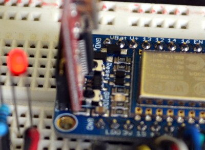
On a breadboard you’ll have two rows not covered by the board on one side, and one row on the other. The board doesn’t have a USB-to-UART bridge but we’re fine with that. On one end of the board you’ll find the common pinout for a USB-to-serial programming cable. Above you can see the programming cable Adafruit sent me with these samples. To the right I tried out my 5V Sparkfun FTDI board and as advertised, the HUZZAH can be programmed with either 3.3v or 5V logic levels.

The one thing I noticed is that the two buttons are a bit tricky to get at with the programmers connected, especially the FTDI board. For the second module I may supply my own right-angle header to get around that. Of course doing so would cover part of the breadboard so this is probably six of one, half dozen of the other.

I love it that they supply the pin headers but don’t solder them. Sometimes I prefer pin sockets or unpopulated pads, and this makes it easy for me to make that choice like the right-angle one I mentioned above. It’s something small but I also appreciate that the pinheaders in the package were not the minimum number necessary for this board — there were a few extra pins. You need to break them off and sometimes they can break one pin over from where you expected. If it were the minimum number you would either start over or solder a single pin at the end of the row (not ideal). If you screw up snapping these you could conceivably use a set of three pins and the rest as one unit to fix your mistake. Maybe I’m weird but it’s the small things in life!

Programming Options: NodeMCU and Lua

The board ships with this firmware on it. I was up and running with the Lua interpreter within three minutes of the package arriving at my door. Seriously, it took me longer to figure out if the USB-to-serial was green or white for TX/RX than it did to connect to my local WiFi Access point. Adafuit’s ‘Hello World’ walkthrough gets you going if you haven’t given this a try before.

Programming Options: Arduino IDE

Adafruit has a Board Manager for Arduino IDE. Perhaps this is common knowledge but I don’t often work with this IDE and it’s the first time I’ve run into it. What can I say, it kicks ass!
I hate setting up tool chains for new chips. With this you add a web address and port number, restart the IDE, and use the board manager to add support for this board. Sweet!

That turns this into an Arduino compatible board which solves something that has long bothered me. I’ve seen a ton of really simple Arduino projects that use the ESP8266 externally. Last month’s porting of the Arduino framework for these chips, coupled with this ready-to-go hardware does away with that nonsense. Seriously, the vast majority of those projects need little to no computing power and will work like a dream when directly programmed onto this chip.

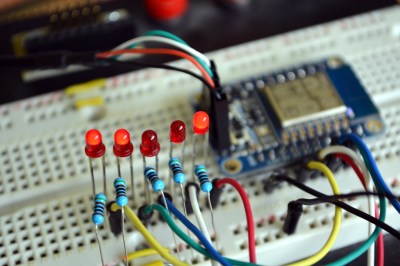
To prove my point, I knocked out this quick binary counter that uses five LEDs as outputs. I’m not leveraging any of the WiFi features on this, but the compiled binary is 174,358 bytes and the Arduino IDE reports this board has a max capacity of 524,288 bytes. It five I/O used for LEDs there are still four more digital pins, the two UART pins, and an ADC input.
Programming Options: esptool

Arduino will overwrite NodeMCU but that’s easy to reflash. I followed [cnlohr’s] direct programming guide to write the binary using esptool. Both this method and the Arduino method are directly programming the EEPROM on the module. This is exactly the same method you’d use if you wanted to develop natively using the Espressif or the Open Source SDKs. Here’s the commands I used to reflash the NodeMCU firmware:

sudo python esptool.py --port /dev/ttyUSB0 write_flash 0x0000 /home/mike/Downloads/nodemcu_latest.bin

Get the NodeMCU binary from their “latest” folder of github repo.

Conclusion

“Buy as many of these as [Phil] will make for us.” That’s what I’ve asked [Julian], the Hackaday Store manager to do. You should be able to get the Hackaday black version of this in a few weeks. Adafruit is currently sold out but I’m sure they’re racing to remedy this.

These are amazing little boards. The price of $9.95 is crazy considering what you get for it. I’m talking about the entire ecosystem which gives you multiple flavors of programming environments. Adafruit has done a lot to contribute to the code and knowledge base here, but a mammoth portion of this is community developed and I think coming in low on the price is one more way Adafruit has chosen to be a good guy in this ecosystem. The board has a ton of I/O for what it is, and if that’s not enough just, implement I2C, SPI, or UART to couple a beefy uC to the connectivity this one brings to the party. I see zero downside on this board. It’s as close to perfect as you can get.


Filed under: Arduino Hacks, Hackaday Columns, reviews

Arduino vs. Phidgets vs. Gadgeteer

A few days ago, we saw a dev time trial between the Arduino and Phidgets, a somewhat proprietary dev board that is many times more expensive than an Arduino. The time trial was a simple experiment to see which platform was faster to prototype simple circuits. As always in Hackaday comments, there was a ton of comments questioning the validity and bias of the test. Not wanting to let a good controversy go to waste, [Ian Lee] tossed his hat into the ring with the same dev trial with the Gadgeteer.

The Gadgeteer has the same design philosophy as Phidgets: modular components and a unique software system -the Gadgeteer is based on .NET Micro Framework – that allows you to get up and running quickly. Unlike Phidgets, the Gadgeteer is priced competitively with the Arduino, and the mainboard is priced within an order of magnitude of a single ATMega chip.

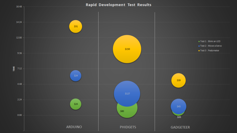
[Ian] pulled off three project with the three development platforms: blinking a LED, moving a servo, and building a pedometer with an accelerometer. For each trial, the time taken and the price of all components were added up. Here’s the relevant graph:

According to the tests, the Gadgeteer won by a large margin. We’re not going to call this a definitive test, and no sane person should think it is. It does, however, highlight the benefits of a well-designed ‘module-based’ development system combined with a good IDE: the Gadgeteer is consistently faster than Phidgets, and just a bit more expensive than an Arduino.

While a time trial consisting of one developer writing code to blink a LED, move a servo, and read a pedometer is hardly enough to make any conclusions, it does demonstrate that the Gadgeteer isn’t that much more expensive than using an Arduino. We’ll leave the rest of the discussion to the commentors below.


Filed under: reviews, Software Development

Arduino vs. Phidgets – Dev Time Trials

Is developing on an Arduino too slow? Are Phidgets too expensive? When might you use one or the other? Hackaday regular [Ken] breaks down what he learned from three experimental time trials.

The main development differences between Arduino and Phidgets are a mix of flavor preferences and some hard facts. The Arduino is open source, Phidgets are proprietary. Arduino requires a mix of hard- and software where Phidgets only needs (and only allows) a connection to a full computer but enables high level languages – it is expected to get the job done sooner and easier. And finally, Arduinos are cheap, Phidgets are 3-5x the cost.

The three time trials were common tasks: 1. Blink an LED. 2. Use a pot to turn a servo. 3. Build a pedometer. For [Ken], the Phidgets won in each of the three experiments, but not significantly: 37%, 45%, and 25% respectively. The difference is only minutes. Even considering time value, for most hackers it is not worth the cost.

In context, the advantages of a mildly more rapid development on the simplest projects are wasted away by needing to rebuild a permanent solution. Chained to a PC, Phidgets are only useful for temporary or fixed projects. For many of our readers that puts them dead in the water. Arduinos may technically be dev kits but are cheap enough to be disposed of in the project as the permanent solution – probably the norm for most of us.

[Ken] points out that for the software crowd that abhor electronics, Phidgets plays to their preferences. Phidgets clips together their pricey peripherals and the rest is all done in code using familiar modern languages and libraries. We wonder just how large this group could still be; Phidgets might have been an interesting kit years ago when the gulf between disciplines was broader but the trend these days is towards everyone knowing a little about everything. Hackaday readers probably represent that trend more than most, but let us know if that seems off.

[Ken]’s article has much more and much better detailed explanations of the experiments and the tradeoffs between the platforms.

If you enjoy watching parallel engineering, see the time-lapse video below for a split screen of the time trials.


Filed under: reviews, Software Development