Posts with «magnet» label

Building This Mechanical Digital Clock Took Balls

In the neverending quest for unique ways to display the time, hackers will try just about anything. We’ve seen it all, or at least we thought we had, and then up popped this purely mechanical digital clock that uses nothing but steel balls to display the time. And we absolutely love it!

Click to embiggen (you’ll be glad you did)

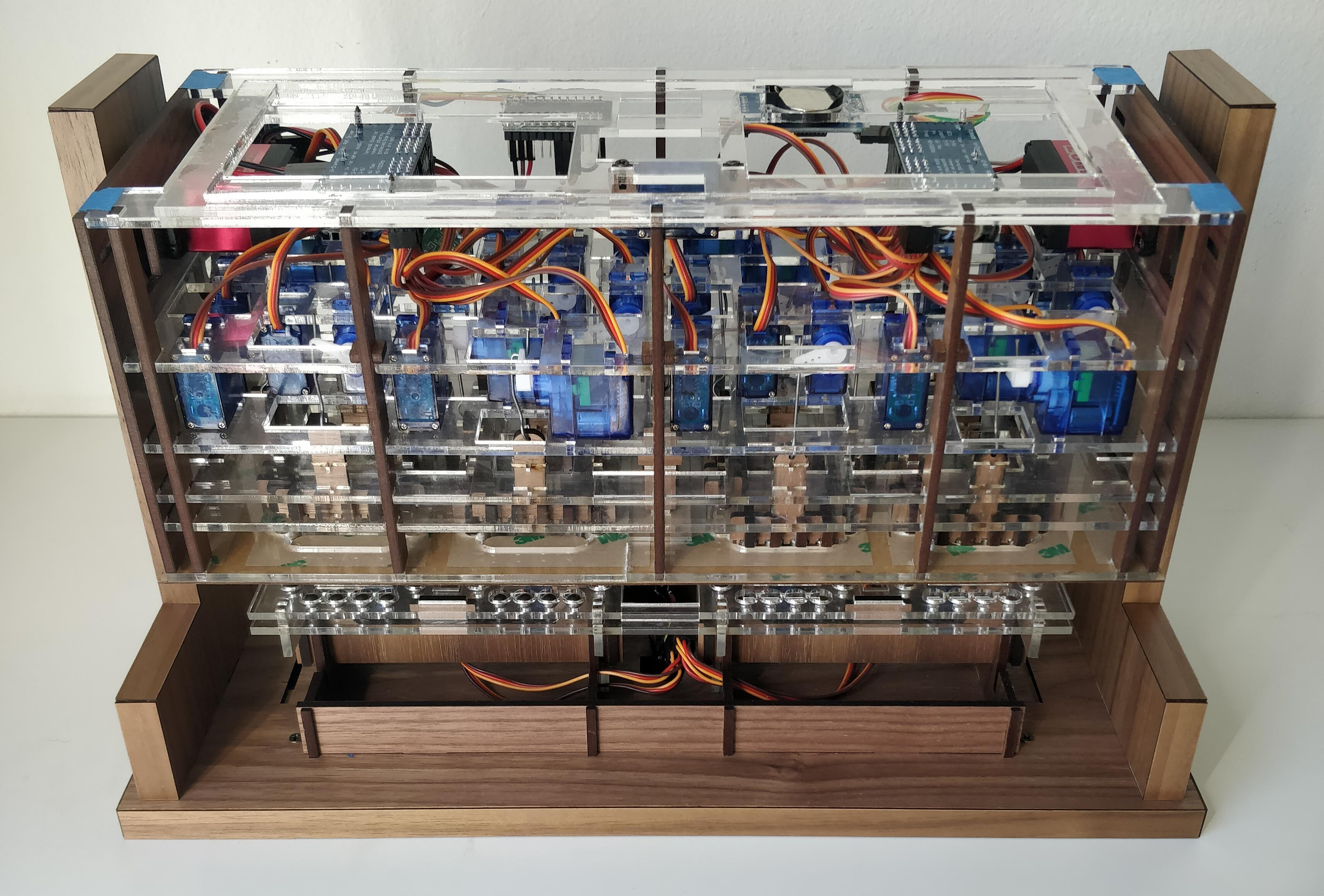
One glimpse at the still images or the brief video below shows you exactly how [Eric Nguyen] managed to pull this off. Each segment of the display is made up of four 0.25″ (6.35 mm) steel balls, picked up and held in place by magnets behind the plain wood face of the clock. But the electromechanical complexity needed to accomplish that is the impressive part of the build. Each segment requires two servos, for a whopping 28 units plus one for the colon. Add to that the two heavy-duty servos needed to tilt the head and the four needed to lift the tray holding the steel balls, and the level of complexity is way up there. And yet, [Eric] still managed to make the interior, which is packed with a laser-cut acrylic skeleton, neat and presentable, as well he might since watching the insides work is pretty satisfying.

We love the level of craftsmanship and creativity on this build, congratulations to [Eric] on making his first Arduino build so hard to top. We’ve seen other mechanical digital displays before, but this one is really a work of art.

Thanks to [Ruhan van der Berg] for the tip.

TMD-1 Makes Turing Machine Concepts Easy to Understand

For something that has been around since the 1930s and is so foundational to computer science, you’d think that the Turing machine, an abstraction for mechanical computation, would be easily understood. Making the abstract concepts easy to understand is what this Turning machine demonstrator aims to do.

The TMD-1 is a project that’s something of a departure from [Michael Gardi]’s usual fare, which has mostly been carefully crafted recreations of artifacts from the early days of computer history, like the Minivac 601  trainer and the DEC H-500 computer lab. The TMD-1 is, rather, a device that makes the principles of a Turing machine more concrete. To represent the concept of the “tape”, [Mike] used eight servo-controlled flip tiles. The “head” of the machine conceptually moves along the tape, its current position indicated by a lighted arrow while reading the status of the cell above it by polling the position of the servo.

Below the tape and head panel is the finite state machine through which the TMD-1 is programmed. [Mike] limited the machine to three states and four transitions, each of which is programmed by placing 3D-printed tiles on a matrix. Magnets were inserted into cavities during printing; Hall Effect sensors in the PCB below the matrix read the pattern of magnets to determine which tiles are where. The video below shows the TMD-1 counting from 0 to 10, which is enough to demonstrate the basics of Turing machines.

It’s hard not to comment on the irony of a Turing machine being run by an Arduino, but given that [Mike]’s goal was to make abstract concepts easy to understand, it makes perfect sense to leverage the platform rather than try to do this with discrete logic. And you can’t argue with results — TMD-1 made Turing machines clear to us for the first time.

Magnetic Attraction Of Microduino mCookie Modules

We’ve seen countless different robot kits promoted for STEM education, every one of which can perform the robotic “Hello World” task of line following. Many were in attendance at Maker Faire Bay Area 2019 toiling in their endless loops. Walking past one such display by Microduino, Inc. our attention was caught by a demonstration of their mCookie modules in action: installing a peripheral module took less than a second with a “click” of magnets finding each other.

Many Arduino projects draw from an ecosystem of Arduino shields. Following that established path, Microduino had offered tiny Arduino-compatible boards and peripherals which connected with pins and headers just like their full-sized counterparts. Unfortunately their tiny size also meant their risk of pin misalignment and corresponding damage would be higher as well. mCookie addresses this challenge by using pogo pins for electrical contacts, and magnets to ensure proper alignment. Now even children with not-quite-there-yet dexterity can assemble these modules, opening up a market to a younger audience.

Spring loaded electric connections are a popular choice for programming jigs, and we’ve seen them combined with magnets for ideas like modular keyboards, and there are also LittleBits for building simple circuits. When packaged with bright colorful LEGO-compatible plastic mounts, we have the foundation of an interesting option for introductory electronics and programming. Microduino’s focus at Maker Faire was promoting their Itty Bitty Buggy, which at $60 USD is a significantly more affordable entry point to intelligent LEGO creations than LEGO’s own $300 USD Mindstorm EV3. It’ll be interesting to see if these nifty mCookie modules will help Microduino differentiate themselves from other LEGO compatible electronic kits following a similar playbook.

Flying the Friendly Skies with A Hall Effect Joystick

There are plenty of PC joysticks out there, but that didn’t stop [dizekat] from building his own. Most joysticks mechanically potentiometers or encoders to measure position. Only a few high-end models use Hall effect sensors. That’s the route [dizekat] took.

Hall effect sensors are non-contact devices which measure magnetic fields. They can be used to measure the position and orientation of a magnet. That’s exactly how [dizekat] is using a trio of sensors in his design. The core of the joystick is a universal joint from an old R/C car. The center section of the joint (called a spider) has two one millimeter thick disc magnets glued to it. The Hall sensors themselves are mounted in the universal itself. [Dizekat] used a small piece of a chopstick to hold the sensors in position while he found the zero point and glued them in. A third Hall effect sensor is used to measure a throttle stick positioned on the side of the box.

An Arduino micro reads the sensors and converts the analog signal to USB.  The Arduino Joystick Library by [Matthew Heironimus] formats the data into something a PC can understand.

While this is definitely a rough work in progress, we’re excited by how much [dizekat] has accomplished with simple hand tools and glue. You don’t need a 3D printer, laser cutter, and a CNC to pull off an awesome hack!

If you think Hall effect sensors are just for joysticks, you’d be wrong – they work as cameras for imaging magnetic fields too!

Hack a Day 18 Jan 09:00

Tertiarm - low cost, 3d printed robot arm based on Ikea lamp

Primary image

What does it do?

Move things, push buttons, etc.

Cost to build

Embedded video

Finished project

Complete

Number

Time to build

Type

URL to more information

Weight

read more

Let's Make Robots 07 Feb 15:54

Tertiarm - low cost, 3d printed robot arm based on Ikea lamp

Primary image

What does it do?

Move things, push buttons, etc.

Cost to build

Embedded video

Finished project

Complete

Number

Time to build

Type

URL to more information

Weight

read more

Let's Make Robots 07 Feb 15:54

Tertiarm - low cost, 3d printed robot arm based on Ikea lamp

Primary image

What does it do?

Move things, push buttons, etc.

Cost to build

Embedded video

Finished project

Complete

Number

Time to build

Type

URL to more information

Weight

read more

Let's Make Robots 07 Feb 15:54

Newton’s Cradle for Those Too Lazy to Procrastinate

Desk toys are perfect for when you don’t want to work. There’s a particularly old desk toy called the Newton’s cradle. If you don’t know the name, you’d still recognize the toy. It is some ball bearings suspended in midair on strings. If you pull back, say, two balls and let them swing to impact the other balls, the same number of balls on the other side will fly out. When they return, the same number will move on the other side and this repeats until friction wears it all down.

We think [JimRD] might be carried away on procrastination. You see, he not only has a Newton’s cradle, he has automated it with an Arduino. According to [Jim], this is his third attempt at doing so. You can see the current incarnation in the video, below.

There are two servos. One pulls back the balls and releases them and the other stops the balls in anticipation of the next operation. The servo that pulls the balls back is clearly magnetic. At first, we thought it was an electromagnet and that deenergizing it released the balls. That’s not the case. Instead, the servo arm has a permanent magnet, but foam decouples it from the ball so that if the arm pulls far enough away, the ball can escape.

Because of the differences in magnets, ball bearings, and other factors, if you try to duplicate this, you’ll probably have to experiment a little with the angles and speeds in the code. The ball stop servo is probably unnecessary, as long as you don’t mind waiting for the thing to wind down on its own.

If you don’t have a cradle, you could always make one yourself. We’d probably avoid using light bulbs, though.


Filed under: Arduino Hacks

Arduino Stroboscope Animation


UPDATE: Magzor has just started a Kickstarter campaign. Please check it out to get a good package deal on many of their components. Many of which were used in this tutorial.
 
This tutorial will show you how to build your own Stroboscopic Animator using Magzor's Mechanotronic Design Portal as a starting point. Magzor Corporation is a business in California that is trying really hard to simplify robotic design. They want to enable users with little to no engineering experience to design and manufacture a custom robot by themselves in a matter of hours.
What is a stroboscope? A stroboscope is an instrument that uses a strobe light to make a moving object look stationary… We will use this feature to create an interesting 4 picture animation on a rotating disk.


Have a look at the video below to see the project in action, and the MDP process walk-through:


Video


Parts Required:


Magzor Schematic Diagram

Click to zoom ...

 
Further build instructions can be obtained by selecting the components in the Mechanotronics Design Portal within the Magzor website. Generating the build, and then selecting "Setup Instructions" tab at the top of the page. See video above to see this process in action.


Arduino Sketch


Make sure to copy and paste the following code into your Arduino IDE. It doesn't seem to work directly from the browser. You also need to install the Arduino Magzor I2C library ( http://magzor.com/downloads/ )


Putting it together


Arduino MEGA


Magzor I2C board


MIC Boards


MIC Boards Assembled


Sensors, Modules and Shields - all put together


Motor with Bracket and Wire


Picture lined up with magnet on disk


Stroboscopic Animation


The Arduino MEGA microcontroller listens for the hall effect sensor to be triggered by the south facing side of the magnet on the underside of the rotating disk. As the magnet moves over the hall effect sensor, the sensor is triggered and the Arduino instructs the LED to blink for a fraction of a second. By manipulating the delay after the trigger time, we can get the LED to blink when one of the four images on the rotating disk is towards the front position. And if we get the timing right, we can make a simple animation.
 
If you watch the video above, you will see that the image bounces around a little bit. The duration of each frame is determined by the speed of the rotating disk (or motor), and the number of LED flashes per frame. Any changes in rotation speed will affect the position of the picture when the LED blinks. My rotating disk is not completely semetrical or centred correctly, and therefore a bit jumpy… but you get the idea. Bold images with high contrast seem to work best… Precision is key for this type of project. And if you can get the disk to rotate at a constant speed, you could probably do away with the hall effect sensors and magnets… however, in my case, these were essential in getting the project to work as intended.
 
This project is a lot of fun. You can really get creative by making your own pictures or 3 dimensional models (for a stop motion effect). Try different colours. It really is quite cool.


Concluding Comments


I would like to thank Magzor for supplying the components used in this tutorial, and letting me try out their MDP process. I really like the concept, the one stop shop which looks after you from beginning to end. Providing everything I needed to get the project off the ground. The point of this exercise was to go through the entire process of selecting the parts, build the project, and get it up and running. And I have done that in no time at all.
 
There is only one library to download and install, and the good thing is that you don't have to go hunting for it. The latest "correct" working version of the library is easy to find, right there on the Magzor website… Speaking of the Magzor website, please make sure to take a quick look around. It is quite impressive.
 
  UPDATE: Magzor has just started a Kickstarter campaign. Please check it out to get a good package deal on many of their components. Many of which were used in this tutorial.


If you like this page, please do me a favour and show your appreciation :

 
Visit my ArduinoBasics Google + page.
Follow me on Twitter by looking for ScottC @ArduinoBasics.
I can also be found on Pinterest and Instagram.
Have a look at my videos on my YouTube channel.


This project would not have been possible without the collaborative effort from Magzor Corporation.
Please visit their site and check out the MDP.


However, if you do not have a google profile...
Feel free to share this page with your friends in any way you see fit.

Arduino Stroboscope Animation


This tutorial will show you how to build your own Stroboscopic Animator using Magzor's Mechanotronic Design Portal as a starting point. Magzor Corporation is a business in California that is trying really hard to simplify robotic design. They want to enable users with little to no engineering experience to design and manufacture a custom robot by themselves in a matter of hours.

What is a stroboscope? A stroboscope is an instrument that uses a strobe light to make a moving object look stationary… We will use this feature to create an interesting 4 picture animation on a rotating disk.


Have a look at the video below to see the project in action, and the MDP process walk-through:


Video


Parts Required:


Magzor Schematic Diagram

Click to zoom ...


Further build instructions can be obtained by selecting the components in the Mechanotronics Design Portal within the Magzor website. Generating the build, and then selecting "Setup Instructions" tab at the top of the page. See video above to see this process in action.


Arduino Sketch


Make sure to copy and paste the following code into your Arduino IDE. It doesn't seem to work directly from the browser. You also need to install the Arduino Magzor I2C library ( http://magzor.com/downloads/ )


Putting it together


Arduino MEGA


Magzor I2C board


MIC Boards


MIC Boards Assembled


Sensors, Modules and Shields - all put together


Motor with Bracket and Wire


Picture lined up with magnet on disk


Stroboscopic Animation


The Arduino MEGA microcontroller listens for the hall effect sensor to be triggered by the south facing side of the magnet on the underside of the rotating disk. As the magnet moves over the hall effect sensor, the sensor is triggered and the Arduino instructs the LED to blink for a fraction of a second. By manipulating the delay after the trigger time, we can get the LED to blink when one of the four images on the rotating disk is towards the front position. And if we get the timing right, we can make a simple animation.
 
If you watch the video above, you will see that the image bounces around a little bit. The duration of each frame is determined by the speed of the rotating disk (or motor), and the number of LED flashes per frame. Any changes in rotation speed will affect the position of the picture when the LED blinks. My rotating disk is not completely semetrical or centred correctly, and therefore a bit jumpy… but you get the idea. Bold images with high contrast seem to work best… Precision is key for this type of project. And if you can get the disk to rotate at a constant speed, you could probably do away with the hall effect sensors and magnets… however, in my case, these were essential in getting the project to work as intended.
 
This project is a lot of fun. You can really get creative by making your own pictures or 3 dimensional models (for a stop motion effect). Try different colours. It really is quite cool.


Concluding Comments


I would like to thank Magzor for supplying the components used in this tutorial, and letting me try out their MDP process. I really like the concept, the one stop shop which looks after you from beginning to end. Providing everything I needed to get the project off the ground. The point of this exercise was to go through the entire process of selecting the parts, build the project, and get it up and running. And I have done that in no time at all.
 
There is only one library to download and install, and the good thing is that you don't have to go hunting for it. The latest "correct" working version of the library is easy to find, right there on the Magzor website… Speaking of the Magzor website, please make sure to take a quick look around. It is quite impressive.


If you like this page, please do me a favour and show your appreciation :

 
Visit my ArduinoBasics Google + page.
Follow me on Twitter by looking for ScottC @ArduinoBasics.
I can also be found on Pinterest and Instagram.
Have a look at my videos on my YouTube channel.


This project would not have been possible without the collaborative effort from Magzor Corporation.
Please visit their site and check out the MDP.


However, if you do not have a google profile...
Feel free to share this page with your friends in any way you see fit.