First off, sometimes you just don’t need the speed. When you’re just blinking LEDs on a human timescale, the general-purpose Arduino functions are good enough. I’ve written loads of useful firmware that fits this description. When the timing requirements aren’t tight, slow as dirt can be fast enough.
But eventually you’ll want to build a project where the old slow-speed pin toggling just won’t cut it. Maybe it’s a large LED matrix, or maybe it’s a motor-control application where the loop time really matters. Or maybe it’s driving something like audio or video that just needs more bits per second. One way out is clever coding, maybe falling back to assembly language primitives, but I would claim that the right way is almost always to use the hardware peripherals that the chipmakers gave you.
For instance, in the end of the video linked above, the hacker wants to drive a large shift register string that’s lighting up an LED matrix. That’s exactly what SPI is for, and coming to this realization makes the project work with timing to spare, and in just a few lines of code. That is the way.
Which brings me to the double-edged sword that the Arduino’s abstraction creates. By abstracting away the chips’ hardware peripherals, it makes code more portable and certainly more accessible to beginners, who don’t want to learn about SPI and I2C and I2S and DMA just yet. But by hiding the inner workings of the chips in “user friendly” libraries, it blinds new users to the useful applications of these same hardware peripherals that clever chip-design engineers have poured their sweat and brains into making do just exactly what we need.
This isn’t really meant to be a rant against Arduino, though. Everyone has to start somewhere, and the abstractions are great for getting your feet wet. And because everything’s open source anyway, nothing stops you from digging deeper into the datasheet. You just have to know that you need to. And that’s why we write up videos like this every five years or so, to show the next crop of new hackers that there’s a lot to gain underneath the abstractions.
This article is part of the Hackaday.com newsletter, delivered every seven days for each of the last 200+ weeks. It also includes our favorite articles from the last seven days that you can see on the web version of the newsletter.
Want this type of article to hit your inbox every Friday morning? You should sign up!
In the early 2000s, the idea that you could write programs on microcontrollers that did things in the physical world, like run motors or light up LEDs, was kind of new. At the time, most people thought of coding as stuff that stayed on the screen, or in cyberspace. This idea of writing code for physical gadgets was uncommon enough that it had a buzzword of its own: “physical computing”.
You never hear much about “physical computing” these days, but that’s not because the concept went away. Rather, it’s probably because it’s almost become the norm. I realized this as Tom Nardi and I were talking on the podcast about a number of apparently different trends that all point in the same direction.
We started off talking about the early days of the Arduino revolution. Sure, folks have been building hobby projects with microcontrollers built in before Arduino, but the combination of a standardized board, a wide-ranging software library, and abundant examples to learn from brought embedded programming to a much wider audience. And particularly, it brought this to an audience of beginners who were not only blinking an LED for the first time, but maybe even taking their first steps into coding. For many, the Arduino hello world was their coding hello world as well. These folks are “physical computing” natives.
Now, it’s to the point that when Arya goes to visit FOSDEM, an open-source software convention, there is hardware everywhere. Why? Because many successful software projects support open hardware, and many others run on it. People port their favorite programming languages to microcontroller platforms, and as they become more powerful, the lines between the “big” computers and the “micro” ones starts to blur.
And I think this is awesome. For one, it’s somehow more rewarding, when you’re just starting to learn to code, to see the letters you type cause something in the physical world to happen, even if it’s just blinking an LED. At the same time, everything has a microcontroller in it these days, and hacking on these devices is also another flavor of physical computing – there’s code in everything that you might think of as hardware. And with open licenses, everything being under version control, and more openness in open hardware than we’ve ever seen before, the open-source hardware world reflects the open-source software ethos.
Are we getting past the point where the hardware / software distinction is even worth making? And was “physical computing” just the buzzword for the final stages of blurring out those lines?
This article is part of the Hackaday.com newsletter, delivered every seven days for each of the last 200+ weeks. It also includes our favorite articles from the last seven days that you can see on the web version of the newsletter.
Want this type of article to hit your inbox every Friday morning? You should sign up!
Good news out of Mars from the little lunchbox that could — in the seven times that MOXIE has run since it arrived in February 2021, it has reached its target production of six grams of oxygen per hour, which is in line with the output of a modest tree here on Earth. The research team which includes MOXIE engineers report that although the solid oxide electrolysis machine has shown it can produce oxygen at almost any time or day of the Martian scale, they have not shown what MOXIE can do at dawn or dusk, when the temperature changes are substantial, but they say they have ‘an ace up (their) sleeve’ that will let them do that. We can’t wait to see what they mean.
In other, somewhat funnier space news — early last Sunday morning, the ESA’s Solar Orbiter was cruising by Venus as part of a gravity-assist maneuver to get the Orbiter closer to the Sun. Two days before the Orbiter was to reach its closest point to the spacious star, it spat a coronal mass ejection in the general direction of both Venus and the Orbiter (dibs on that band name), as if to say ‘boo’. Fortunately, the spacecraft is designed to withstand such slights, but the same cannot be said for Venus — these events have their way with Venus’ atmosphere, depleting it of gasses.
Is this not the most Hackaday-esque thing you’ve ever heard of? A solar-powered, Arduino-driven cockroach. Not a robot, an actual cockroach with a backpack. Why? Cyborg insects for urban search and rescue missions, obviously. We’d make some quip like ‘all it needs is a Nixie tube’, but in all seriousness, that would just weigh them down needlessly.
So anyway, here’s (an ‘Arduino guitar device’ playing) Wonderwall.
[Hal Rodriguez] and [Sahrye Cohen] of Amped Atelier focus on creating interactive wearable garments with some fairly high standards. Every garment must be pretty, and has to either be controllable by the wearer, through a set of sensors, or even by the audience via Bluetooth. Among their past creations are a dress with color sensors and 3D-printed scales on the front that change color, and a flowing pantsuit designed for a dancer using an accelerometer to make light patterns based on her movements.
Conductive Melody — a wearable musical instrument that is the focus of [Sahrye] and [Hal]’s Remoticon 2021 talk — was created for a presentation at Beakerhead Festival, a multi-day STEAM-based gathering in Calgary. [Sahrye] and [Hal] truly joined forces for this one, because [Sahrye] is all about electronics and costuming, and [Hal] is into synths and electronic music. You can see the demo in the video after the break.
The dress’s form is inspired by classical instruments and the types of clothing that they in turn inspired, such as long, generous sleeves for harp players and pianists. So [Hal] and [Sahrye] dreamed up a dress with a single large playable sleeve that hangs down from the mid- and upper arm. The sleeve is covered with laser-cut conductive fabric curlicues that look like a baroque interpretation of harp strings. Play a note by touching one of these traces, and the lights on the front of the dress will move in sync with the music.
[Sahrye] started the dress portion of Conductive Melody with a sketch of the garment’s broad strokes, then painted a more final drawing with lots of detail. Then she made a muslin, which is kind of the breadboard version of a project in garment-making where thin cotton fabric is used to help visualize the end result. Once satisfied with the fit, [Sahrye] then made the final dress out of good fabric. And we mean really good fabric — silk, in this case. Because as [Sahrye] says, if you’re going to make a one-off, why not make as nicely as possible? We can totally get behind that.
[Sahrye] says she is always thinking about how a wearable will be worn, and how it will be washed or otherwise cared for. That sequined and semi-sheer section of the bodice hides the LEDs and their wiring quite well, while still being comfortable for the wearer.
Inside the sleeve is an MPRP121 capacitive touch sensor and an Arduino that controls the LEDs and sends the signals to a Raspberry Pi hidden among the ruffles in the back of the dress.
The Pi is running Piano Genie, which can turn eight inputs into an 88-key piano in real time. When no one is playing the sleeve, the lights have a standby mode of mellow yellows and whites that fade in and out slowly compared to the more upbeat rainbow of musical mode.
We love to see wearable projects — especially such fancy creations! — but we know how finicky they can be. Among the lessons learned by [Sahrye] and [Hal]: don’t make your conductive fabric traces too thin, and silver conductive materials may tarnish irreparably. We just hope they didn’t have to waste too much conductive fabric or that nice blue silk to find this out.
Sad news from Germany, with the recent passing of a legend in the crypto community: Mr. Goxx, the crypto-trading hamster. The rodent rose to fame in the crypto community for his trades, which were generated at random during his daily exercise routines — his exercise wheel being used like a roulette wheel to choose a currency, and a pair of tunnels determined whether the transaction would be a buy or sell. His trading career was short, having only started this past June, but he was up 20% over that time — that’s nothing to sneeze at. Our condolences to Mr. Goxx’s owners, and to the community which sprung up around the animal’s antics.
It might seem a little early to start planning which conferences you’d like to hit in 2022, but some require a little more lead time than others. One that you might not have heard of is DINACON, the Digital Naturalism Conference, which explores the intersection of technology and the natural world. The con is set for the entire month of July 2022 and will be held in Sri Lanka. It has a different structure than most cons, in that participants attend for a week or so on a rotating basis, much like a biology field station summer session. It sounds like a lot of fun, and the setting couldn’t be more idyllic.
If you haven’t already killed your holiday gift budget buying NFTs, here’s something you might want to consider: the Arduino Uno Mini Limited Edition. What makes it a Limited Edition, you ask? Practically, it’s the small footprint compared to the original Uno and the castellated edges, but there are a bunch of other extras. Each elegant black PCB with gold silk screening is individually numbered and comes in presentation-quality packaging. But the pièce de résistance, or perhaps we should say the cavallo di battaglia, is that each one comes with a hand-signed letter from the Arduino founders. They honestly look pretty sharp, and at $45, it’s really not a bad collector’s piece.
And finally, the YouTube algorithm giveth again, when this infrastructure gem popped up in our feed. You wouldn’t think there’d be much of interest to see in a water main repair, but you’d be wrong, especially when that main is 50′ (15 m) below the surface, and the repair location is 600′ (183 m) from the access hatch. Oh yeah, and the pipe is only 42″ (1 m) in diameter, and runs underneath a river. There’s just so much nope in this one, especially since the diver has to swim into a special turning elbow just to get pointed in the right direction; how he turns around to swim out is not worth thinking about. Fascinating tidbits include being able to see the gravel used to protect the pipe in the riverbed through the crack in the pipe, and learning that big water mains are not completely filled, at least judging by the small air space visible at the top of the pipe. Those with claustrophobia are probably best advised to avoid this one, but it’s still amazing to see how stuff like this is done.
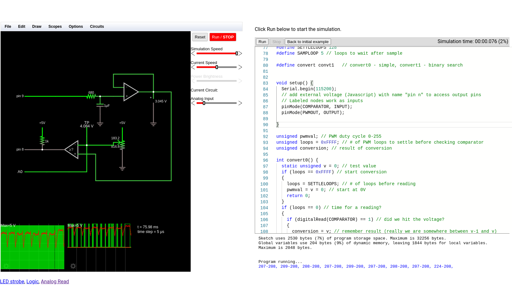
There was a time when building electronics and building software were two distinct activities. These days, almost any significant electronic project will use a CPU somewhere, or — at least — could. Using a circuit simulator can get you part of the way and software simulators abound. But cosimulation — simulating both analog circuits and a running processor — is often only found in high-end simulation products. But I noticed the other day the feature quietly snuck into our favorite Web-based simulator, Falstad.
The classic simulator is on the left and the virtual Arduino is on the right.
Back in March, the main project added work from [Mark McGarry] to support AVR8js written by [Uri Shaked]. The end result is you can have the circuit simulator on the left of the screen and a Web-based Arduino IDE on the right side. But how does it work beyond the simple demo? We wanted to find out.
The screen looks promising. The familiar simulator is to the left and the Arduino IDE — sort of — is to the right. There’s serial output under the source code, but it doesn’t scroll very well, so if you output a lot of serial data, it is hard to read.
Nothing is Perfect
I love just about everything about the Falstad simulator and having an Arduino cosimulation is great. But there is one really important issue that may get resolved eventually. Normally when you draw a schematic you can save it as text or encoded in a link. If you click the link or import the text, everything is back to the way it was when you saved. I use that in a lot of Circuit VR posts so you can click on a circuit and see it live.
However, the simulator does not save the source code in the virtual Arduino. You have to do that yourself. That means if you have everything working, save your circuit, and close your browser you’ll have to recreate your Arduino code next time. Luckily, I tested this out before I lost any work. There should be a big red warning on the page, though.
What that means, though, is that I can’t give you a link to follow along with examples. Here’s what you can do:
Copy the text from the top of the source code comments and paste it into the simulator (detailed instructions in the comments).
Just don’t forget to save your source code changes. If you make changes to the circuit, you’ll want to export them to text and copy them into the source code so you can save everything together.
An Example
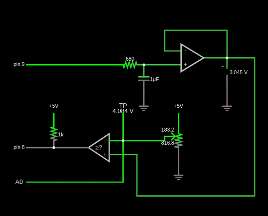
Test schematic.
I wanted an easy example that showed the benefit of using cosimulation. I settled on looking at some alternatives for doing an analog to digital conversion using successive approximation. A virtual potentiometer provides an input voltage. There’s a comparator and a buffered PWM output. Here’s the schematic:
Input/Output
There are three interface points to the Arduino. The PWM output is set as an external voltage using the “Inputs and Sources” components (remember, the output from the Arduino is the input to the circuit). Conversely, the comparator output and the connection to the Arduino’s analog converter (A0) are labeled nodes from the “Output and Labels” menu. The names are significant, including the spaces.
The Code
In theory, the code is pretty simple. You guess a voltage and read the output of the comparator to see if you are right. There are two methods in the code and you can switch between them by setting the convert define to convert0 or convert1.
On every pass through the loop, the code calls one of the convert functions to manage the successive approximation process through a different algorithm. It also updates the PWM output on each pass.
The first approximation algorithm is very simple but not very efficient. It guesses each output voltage starting at 0 and moving up 1/255 V on each pass. When the comparator goes from false to true, you know the input voltage must be less than the current voltage but more than the previous voltage.
The second algorithm is smarter and works like a binary search. The first guess is 128/255. That voltage is either higher or lower than our target. If it is lower, we remember that the bit should be on and, either way, move to the next bit. In other words, the second test will be either 64/255 or 128/255 + Simulide64/255. Again, the new value is either high or low and will determine the state of the next bit.
The first algorithm could finish fast or it may have to count all the way to 255 to find the answer. The second algorithm always takes 8 measurements. There’s no way for the comparator to tell us our reference voltage is exactly equal to the input even if we could define what that means for an analog signal. So we have to measure each bit and decide if it should be on or off.
The output appears in the serial terminal. The first number is the result of the conversion and the second is the value from the built-in converter for the same voltage.
Voltage Reference
Generating the reference voltage is the key. It would be possible to use 8 output bits and an R2R network to generate an output voltage quickly, but that eats up a lot of pins. Instead, I used one pin to generate voltages using PWM. This isn’t as fast, of course, because you have to allow the RC filter time for the voltage to reach its desired value.
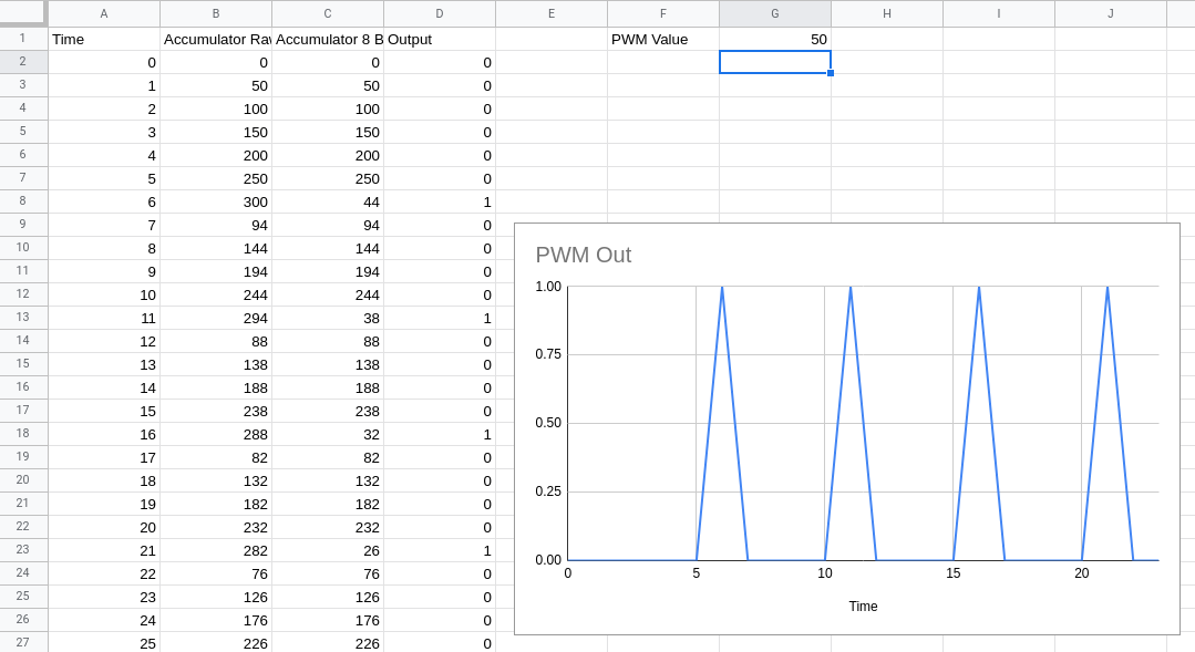
Pin 9 generates a PWM signal using a time-honored technique. Suppose you want to generate 20/255 (about 8% duty cycle). You take an 8-bit accumulator and add 20 to it repeatedly. The PWM output is the carry out of the top bit. You can find a spreadsheet with the logic, but you’ll have to imagine the output waves are squares since the spreadsheet helpfully draws straight lines between points.
This spreadsheet models the PWM output logic.
To do this right, the code should run on a precise interrupt and equalize the time between outputs. However, for this quick demo, I’ve assumed the time for calling the main loop will be regular enough. I considered doing it on an interrupt, but — honestly — I’m not sure how faithful the simulator is, how time-accurate it is, and it doesn’t appear you can easily add libraries to it, so you’d almost certainly have to manage the interrupts at the register level.
The output signal gets smoothed by an RC filter. The values here are interesting and it is fun to watch the scope as you vary the parameters in this part of the circuit. You want a noise-free reference signal. So that implies a big capacitor. However, a big capacitor takes more time to charge and discharge, so the voltage will take longer to settle. It is a classic trade-off. Do you want a noisy fast response or a clean slow response?
In this case, the pot probably doesn’t change very fast, but in real life, the input signal might be changing all the time and you might even consider a sample and hold on that input to make sure it doesn’t change while you are in the middle of guessing.
Tuning
Obviously, you can change the RC values easily in the simulator. It is even possible to add sliders to set the values graphically while the simulation is running (the pot is set up to do this already). Changing the code, however, requires a stop and restart.
In the code, you can change the number of loop cycles the convert routines wait to allow a new PWM value to settle (SETTLELOOPS) and how long to pause between readings (SAMPLOOP). The interactions between these numbers and the RC values are critical. Larger RC time constants require more time to produce correct results. Smaller RC numbers will require less time, but the noise will introduce errors. Take your pick.
PWM signal with 2uF capacitor.
PWM signal with 47uF capacitor.
The Verdict
This is a toy example. The PWM generation suffers from some issues and PWM isn’t a great idea for a conversion reference. Still, it shows a good bit of what is possible with the cosimulation available with Falstad. I am really looking forward to the next time I need some exotic signal fed into a circuit. Just using the Arduino as a function generator will have its uses.
I do wish you could add libraries and save an entire project more easily. Still, there are many what-if scenarios you could simulate quickly and easily using this tool. Since it has only been in the code base for a few months, I’m hopeful some of these issues will work out over time. Add debugging to the mix, and it would be a real winner.
Tinkercad allows you to simulate Arduino, but not with the circuit sophistication of Falstad. It does require an install, but we are always surprised we don’t hear more about Simulide.
We’ve all become familiar with the Arduino ecosystem by now, to the point where it’s almost trivially easy to whip up a quick project that implements almost every aspect of its functionality strictly in code. It’s incredibly useful, but we tend to lose sight of the fact that our Arduino sketches represent a virtual world where the IDE and a vast selection of libraries abstract away a lot of the complexity of what’s going on inside the AVR microcontroller.
While it’s certainly handy to have an environment that lets you stand up a system in a matter of minutes, it’s hardly the end of the story. There’s a lot to be gained by tapping into the power of assembly programming on the AVR, and learning how to read the datasheet and really run the thing. That was the focus of Uri Shaked’s recent well-received HackadayU course on AVR internals, and it’ll form the basis of this Hack Chat. Then again, since Uri is also leading a Raspberry Pi Pico and RP2040 course on HackadayU in a couple of weeks, we may end up talking about that too. Or we may end up chatting about something else entirely! It’s really hard to where this Hack Chat will go, given Uri’s breadth of interests and expertise, but we’re pretty sure of one thing: it won’t be boring. Make sure you log in and join the chat — where it goes is largely up to you.
Click that speech bubble to the right, and you’ll be taken directly to the Hack Chat group on Hackaday.io. You don’t have to wait until Wednesday; join whenever you want and you can see what the community is talking about.
Gosh, what a shame: it turns out that perhaps 2 billion phones won’t be capable of COVID-19 contact-tracing using the API that Google and Apple are jointly developing. The problem is that the scheme the two tech giants have concocted, which Elliot Williams expertly dissected recently, is based on Bluetooth LE. If a phone lacks a BLE chipset, then it won’t work with apps built on the contact-tracing API, which uses the limited range of BLE signals as a proxy for the physical proximity of any two people. If a user is reported to be COVID-19 positive, all the people whose BLE beacons were received by the infected user’s phone within a defined time period can be anonymously notified of their contact. As Elliot points out, numerous questions loom around this scheme, not least of which is privacy, but for now, something like a third of phones in mature smartphone markets won’t be able to participate, and perhaps two-thirds of the phones in developing markets are not compatible. For those who don’t like the privacy-threatening aspects of this scheme, pulling an old phone out and dusting it off might not be a bad idea.
We occasionally cover stories where engineers in industrial settings use an Arduino for a quick-and-dirty automation solution. This is uniformly met with much teeth-gnashing and hair-rending in the comments asserting that Arduinos are not appropriate for industrial use. Whether true or not, such comments miss the point that the Arduino solution is usually a stop-gap or proof-of-concept deal. But now the purists and pedants can relax, because Automation Direct is offering Arduino-compatible, industrial-grade programmable controllers. Their ProductivityOpen line is compatible with the Arduino IDE while having industrial certifications and hardening against harsh conditions, with a rich line of shields available to piece together complete automation controllers. For the home-gamer, an Arduino in an enclosure that can withstand harsh conditions and only cost $49 might fill a niche.
Speaking of Arduinos and Arduino accessories, better watch out if you’ve got any modules and you come under the scrutiny of an authoritarian regime, because you could be accused of being a bomb maker. Police in Hong Kong allegedly arrested a 20-year-old student and posted a picture of parts he used to manufacture a “remote detonated bomb”. The BOM for the bomb was strangely devoid of anything with wireless capabilities or, you know, actual explosives, and instead looks pretty much like the stuff found on any of our workbenches or junk bins. Pretty scary stuff.
If you’ve run through every binge-worthy series on Netflix and are looking for a bit of space-nerd entertainment, have we got one for you. Scott Manley has a new video that goes into detail on the four different computers used for each Apollo mission. We knew about the Apollo Guidance Computers that guided the Command Module and the Lunar Module, and the Launch Vehicle Digital Computer that got the whole stack into orbit and on the way to the Moon, but we’d never heard of the Abort Guidance System, a backup to the Lunar Module AGC intended to get the astronauts back into lunar orbit in the event of an emergency. And we’d also never heard that there wasn’t a common architecture for these machines, to the point where each had its own word length. The bit about infighting between MIT and IBM was entertaining too.
And finally, if you still find yourself with time on your hands, why not try your hand at pen-testing a military satellite in orbit? That’s the offer on the table to hackers from the US Air Force, proprietor of some of the tippy-toppest secret hardware in orbit. The Hack-A-Sat Space Security Challenge is aimed at exposing weaknesses that have been inadvertantly baked into space hardware during decades of closed development and secrecy, vulnerabilities that may pose risks to billions of dollars worth of irreplaceable assets. The qualification round requires teams to hack a grounded test satellite before moving on to attacking an orbiting platform during DEFCON in August, with prizes going to the winning teams. Get paid to hack government assets and not get arrested? Maybe 2020 isn’t so bad after all.
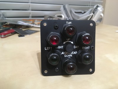
It’s surprisingly easy to misjudge tips that come into the Hackaday tip line. After filtering out the omnipresent spam, a quick scan of tip titles will often form a quick impression that turns out to be completely wrong. Such was the case with a recent tip that seemed from the subject line to be a flight simulator cockpit. The mental picture I had was of a model cockpit hooked to Flight Simulator or some other off-the-shelf flying game, many of which we’ve seen over the years.
I couldn’t have been more wrong about the project that Grant Hobbs undertook. His cockpit simulator turned out to be so much more than what I thought, and after trading a few emails with him to get all the details, I felt like I had to share the series of hacks that led to the short video below and the story about how he somehow managed to build the set despite having no previous experience with the usual tools of the trade.
A Novel and a Film
Grant has been making short films for a while, mainly in collaboration with John Dwyer, an author of historical novels. Grant’s shorts are used as promos for John’s books, and nicely capture the period and settings of John’s novels. Most of these films required little in the way of special sets, relying instead on stock footage and vintage costumes to achieve their look and feel. John’s latest novel would change all that.
Called Mustang, the novel centers on a hotshot fighter pilot in WWII. Grant’s vision for the short to promote the book was inspired by the recent Christopher Nolan film Dunkirk, which featured intricate sequences filmed in the cockpit of a Spitfire. Granted wanted a similar look, and began arranging to use a real P-51 Mustang for filming. That presented immediate problems. First, there aren’t that many of the vintage aircraft left, and those that are still flying usually have anachronistic instruments in the cockpit, like GPS. Also, Grant wanted the instruments to respond as if the plane were airborne, and to have the shadows cast by the canopy into the cockpit suggest aerial maneuvers. Such an effect would be difficult to achieve with a plane stuck on a runway.
That’s when Grant realized that a gimballed cockpit simulator was needed. It could have a period-accurate dashboard, be positioned outdoors to take advantage of natural daylight and real backgrounds rather than CGI, and could be pitched, rolled and yawed to simulate flight. It would be perfect, and it would save the project. There was just one problem: he had no idea how to build it.
Helping Hands
Wisely, Grant turned to his local hackerspace, Dallas Maker Space, for help. There he found not only the tools he lacked, but kindred spirits with the necessary skills and the willingness to share them. They started working on the cockpit instrument panel, which ended up including a combination of actual flight hardware and mocked-up instruments. The fake instruments used steppers and an Arduino to drive the needles, which were controlled by a custom iPad app that was used to animate them live during filming. The real instruments, like the artificial horizon and turn-and-slip indicator, were powered by a vacuum pump and responded to the movements of the simulator on its gimbals.
The gimballed cockpit set for exterior shots. The wide horizon and natural lighting combined with the 3-DOF gimbal make for a very realistic effect.
Mounting this convincing panel into something was an entirely different undertaking. Grant relied heavily on the experience of DMS members to design a structure strong enough to support the actor and allow for the motion needed to create a convincing effect. The cockpit mockup, made from plasma-cut sheet metal and plywood, is mounted to a heavy-duty three-axis gimbal, including a massive bearing from a pallet jack for the yaw axis.
Set and talent, ready for action.
Grant had originally planned to place the mockup on a mountaintop for shooting, much as the Spitfire mockup from Dunkirk was placed on the edge of a cliff to give an unobstructed horizon to simulate flying over the English Channel. When that proved logistically challenging, he set up on an airport runway and used clever camera blocking to avoid shooting the horizon. Grips manually moved the simulator while Grant manipulated the fake instruments and filmed the results, which I think speak for themselves. If only the budget – and on-set safety – would have supported simulating the massive four-blade Mustang propeller, the illusion would have been complete.
I really enjoyed digging into this project and all the hacks that it entailed. Movie magic is as much about hacking as anything else, at least behind the cameras, and it’s good to see what’s possible with a limited budget. We recently featured a low-budget but high-style sci-fi movie set build, and we’ve gone in-depth with a playback designer for the Netflix series Lost in Space, both in these pages and as a Hack Chat.
The Consumer Electronics Show in Las Vegas is traditionally where the big names in tech show off their upcoming products, and the 2020 show was no different. There were new smartphones, TVs, and home automation devices from all the usual suspects. Even a few electric vehicles snuck in there. But mixed in among flashy presentations from the electronics giants was a considerably more restrained announcement from a company near and dear to the readers of Hackaday: Arduino is going pro.
While Arduino has been focused on the DIY and educational market since their inception, the newly unveiled Portenta H7 is designed for professional users who want to rapidly develop robust hardware suitable for industrial applications. With built-in wireless hardware and the ability to run Python and JavaScript out of the box, the powerful dual-core board comes with a similarly professional price tag; currently for preorder at $99 USD a pop, the Portenta is priced well outside of the company’s traditional DIY and educational markets. With increased competition from other low-cost microcontrollers, it seems that Arduino is looking to expand out of its comfort zone and find new revenue streams.
That’s a Lot of Pins
The Portenta H7 is obviously a far cry from the relatively dinky 8-bit Arduinos that we’ve all got filling up our parts drawers. Developed for high performance edge computing applications, the new board is powered by a 32-bit STM32H747XI that utilizes both an ARM Cortex M7 and an M4 running at 480 MHz and 240 MHz respectively. The two cores can work independently, allowing for example one core to run interpreted Python while the other runs code compiled in the Arduino IDE. When they need to work together, the cores can communicate with each other via a Remote Procedure Call (RPC) mechanism.
The new 80-pin connectors on the Portenta
Outwardly, the new board doesn’t look far removed from the modern Arduino form factor we’re used to. The USB connector has been upgraded to a Type-C, but the Portenta still retains the dual rows of pads ready for hand-soldered headers — that’s their more recent pinout that they call the Arduino MKR form factor.
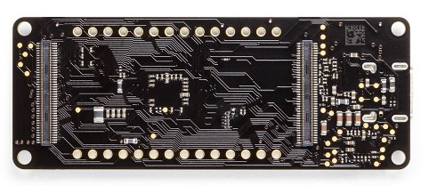
If you look on the back of the board however, you’ll see that they’ve added two 80-pin high density connectors. According to the product page, these are intended to allow the Portenta to simply be plugged into a device as a removable module. The idea being that devices in the field can easily have their Portenta swapped out for an upgraded model. Some digging into the product page documentation section turns up a schematic that lists the connectors as Hirose DF40C-80DP-0.4V(51).
The base model Portenta features 8 MB SDRAM and 16 MB NOR flash, but it can be custom ordered with up to 64 MB of memory and 128 MB of flash should you need it. It’s also possible to delete various interfaces from the board when ordering, so if you don’t want network connectivity or the NXP SE050C2 crypto chip, they can simply be left off. However as of this writing it is unclear as to what minimum order quantity is necessary to unlock this level of customization, or or how much these modifications will change the unit cost.
Year of the Arduino Desktop?
The Portenta Carrier Board
The Portenta H7 is an impressive enough piece of hardware on its own, but when it’s plugged into the optional Carrier Board, things really start to get interesting. The Carrier Board provides full size connectors for all of the onboard peripherals, and according to documentation, turns the Portenta into an eNUC-class embedded computer. There’s even support for DisplayPort to connect a monitor, and miniPCI for expansion cards.
With a fully loaded Portenta H7 slotted into the Carrier Board, it would seem you have the makings of a low-power ARM “desktop” computer. Albeit one that wouldn’t outperform the Raspberry Pi Zero, and which costs several times more.
The Arduino press release and product page doesn’t make any mention of what kind of software or operating system said computer would run, so presumably that’s left as an exercise for the customer. While not particularly well suited to it, the ARM Cortex-M family of processors is capable of running the Linux kernel, so spinning up a “real” OS image for it should be possible. Of course with a maximum of just 64 MB of RAM, you’ll want to keep your performance expectations fairly low.
Where Does Portenta Fit?
We can’t even speculate what a maxed out Portenta would cost, and there’s no pricing or release date for the Carrier Board. But even at $99, the base model Portenta H7 would be a tough sell for hackers and makers who are used to buying dual-core ESP32 boards at 1/10 of the price, or the Teensy 4.0 which has a 600 MHz Cortex-M7 at 1/4 of the price. Which is fine, since this board isn’t intended for the traditional core Arduino audience.
Seeing the carrier board, we can’t help but notice some parallels here with the Raspberry Pi Compute Module. With connections broken out to a SODIMM header, the idea of the Computer Module was to help bridge the gap between the DIY community and the commercial one by offering up a Raspberry Pi in a more rugged form factor that would be easier to integrate into end-user products. But since it wasn’t any cheaper than the stock Pi, there wasn’t a whole lot of incentive to switch over. We haven’t seen consumer products advertising “Raspberry Pi Inside!” so it’s hard to tell if there has been any meaningful adoption from industry.
One has to wonder why any company that has the resources to integrate such an expensive board into their products wouldn’t just come up with their own custom design around the Portenta’s STM32H747XI chip, which even in single quantities, can currently be had for less than $15. The difference may end up coming down to the world-renowned community that surrounds the Arduino brand, and the company’s efforts to modernize their toolchain.