Posts with «calculator» label

Hewlett-Packard 5082-7415 LED Display from 1976

In this article we examine a five digit, seven-segment LED display from Hewlett-Packard, the 5082-7415:

We realise they’re most likely now pure unobtanium, but we like some old display p0rn so here you go.

2025 update – Tronixlabs in Australia has a limited quantity of new, old-stock four-digit QDSP6064 displays. Email john at tronixlabs dot com for more information.

According to the data sheet (HP 5082-series.pdf) and other research this was available for a period of time around 1976 and used with other 5082-series modules in other HP products. Such as the Hewlett-Packard 3x series of calculators, for example:

Using the display is very easy – kudos to the engineers at HP for making a simple design that could be reusable in many applications. The 5082-7415 is a common-cathode unit and wiring is very simple – there are the usual eight anodes for segments a~f and the decimal point, and the five cathodes.

As this module isn’t too easily replaceable, I was very conservative with the power supply – feeding just under 1.6V at 10mA to each of the anode pins. A quick test proved very promising:

Excellent – it worked! But now to get it displaying some sort of interesting way. Using the following hardware…

Don’t forget to use the data sheet (HP 5082-series.pdf). You don’t have to use Arduino – any microcontroller with the appropriate I/O can take care of this.

Here is a simple Arduino sketch that scrolls through the digits with and then without the decimal point:

// Arduino sketch to demonstrate HP 5082-7415 LED Display unit
// John Boxall, April 2012
int clockPin=6;
int latchPin=7;
int dataPin=8;
// array for cathodes - sent to second shift register
byte digits[]={
  B10000000,
  B01000000,
  B00100000,
  B00010000,
  B00001000,
  B11111000}; // use digits[6] to turn all on
// array for anodes (to display 0~0) - sent to first shift register
byte numbers[]={
  B11111100,
  B01100000,
  B11011010,
  B11110010,
  B01100110,
  B10110110,
  B10111110,
  B11100000,
  B11111110,
  B11110110};
void setup()
{
  pinMode(clockPin, OUTPUT);
  pinMode(latchPin, OUTPUT);
  pinMode(dataPin, OUTPUT);
}
void loop()
{
  int i;
  for ( i=0 ; i<10; i++ )
  {
    digitalWrite(latchPin, LOW);
    shiftOut(dataPin, clockPin, LSBFIRST, digits[6]);
    shiftOut(dataPin, clockPin, LSBFIRST, numbers[i]);
    digitalWrite(latchPin, HIGH);
    delay(250);
  }
  // now repeat with decimal point
  for ( i=0 ; i<10; i++ )
  {
    digitalWrite(latchPin, LOW);
    shiftOut(dataPin, clockPin, LSBFIRST, digits[6]);
    shiftOut(dataPin, clockPin, LSBFIRST, numbers[i]+1);
    digitalWrite(latchPin, HIGH);
    delay(250);
  }
}

And the results:

Now for something more useful. Here is a function that sends a single digit to a position on the display with the option of turning the decimal point on or off:

void displayDigit(int value, int posit, boolean decPoint)
// displays integer value at digit position posit with decimal point on/off
{
 digitalWrite(latchPin, LOW);
 shiftOut(dataPin, clockPin, LSBFIRST, digits[posit]);
 if (decPoint==true)
 {
 shiftOut(dataPin, clockPin, LSBFIRST, numbers[value]+1); 
 } 
 else 
 {
 shiftOut(dataPin, clockPin, LSBFIRST, numbers[value]); 
 }
 digitalWrite(latchPin, HIGH);
}

So if you wanted to display the number three in the fourth digit, with the decimal point – use

displayDigit(3,3,true);

with the following result:

We make use of the displayDigit() function in our next sketch. We introduce a new function:

displayInteger(number,cycles);

It accepts a long integer between zero and 99999 (number) and displays it on the module for cycles times:

// Arduino sketch to demonstrate HP 5082-7415 LED Display unit
// Displays numbers on request
// John Boxall, April 2012
int clockPin=6;
int latchPin=7;
int dataPin=8;
// array for cathodes - sent to second shift register
byte digits[]={
 B10000000,
 B01000000,
 B00100000,
 B00010000,
 B00001000,
 B11111000}; // use digits[6] to turn all on
// array for anodes (to display 0~0) - sent to first shift register
byte numbers[]={
 B11111100,
 B01100000,
 B11011010,
 B11110010,
 B01100110,
 B10110110,
 B10111110,
 B11100000,
 B11111110,
 B11110110};
void setup()
{
 pinMode(clockPin, OUTPUT);
 pinMode(latchPin, OUTPUT);
 pinMode(dataPin, OUTPUT);
 randomSeed(analogRead(0));
}
void clearDisplay()
// turns off all digits
{
 digitalWrite(latchPin, LOW);
 shiftOut(dataPin, clockPin, LSBFIRST, 0);
 shiftOut(dataPin, clockPin, LSBFIRST, 0); 
 digitalWrite(latchPin, HIGH);
}
void displayDigit(int value, int posit, boolean decPoint)
// displays integer value at digit position posit with decimal point on/off
{
 digitalWrite(latchPin, LOW);
 shiftOut(dataPin, clockPin, LSBFIRST, digits[posit]);
 if (decPoint==true)
 {
 shiftOut(dataPin, clockPin, LSBFIRST, numbers[value]+1); 
 } 
 else 
 {
 shiftOut(dataPin, clockPin, LSBFIRST, numbers[value]); 
 }
 digitalWrite(latchPin, HIGH);
}
void displayInteger(long number,int cycles)
// displays a number 'number' on the HP display. 
{
 long i,j,k,l,z;
 float f;
 clearDisplay();
 for (z=0; z
void loop()
{
 long l2;
 l2=random(0,100001);
 displayInteger(l2,400);
}

For demonstration purposes the sketch displays random numbers, as shown in the video below:

Update – four-digit versions…

They worked very nicely and can be driven in the same method as the 5082-7415s described earlier. In the following video we have run the same sketches with the new displays:

In the meanwhile, I hope you found this article of interest. Thanks to the Vintage Technology Association website and the Museum of HP Calculators for background information.

To keep up to date with new posts at tronixstuff.com, please subscribe to the mailing list in the box on the right, or follow us on x – @tronixstuff.

I hope you enjoyed reading about the displays. If you find this sort of thing interesting, please consider ordering one or more of my books from amazon.

And as always, have fun and make something.

Walnut Case Sets This Custom Arduino-Powered RPN Calculator Apart from the Crowd

How many of us have an everyday tool that’s truly unique? Likely not many of us; take a look around your desk and turn out your pockets, but more often than not, what you’ll find is that everything you have is something that pretty much everyone else on the planet could have bought too. But not so if you’ve got this beautiful custom RPN calculator in a wooden case.

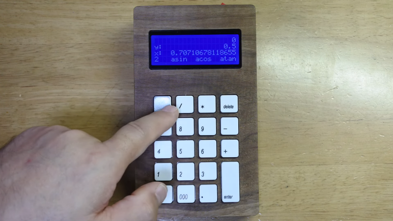
This one comes to us from [Shinsaku Hiura], who generally dazzles us with unique mechanical clocks and displays. This calculator solves a more practical problem — the dearth of RPN calculators on the market with the correct keyboard feel, specifically with the large keys and light touch he desired. Appropriately, the build started with a numeric keypad, which once liberated of its USB interface was reverse-engineered to figure out how the matrix was wired. Next up, a custom PCB to connect the keypad to an Arduino and a 20×4 LCD display was milled up, while a test case was designed and printed to check fitment. The final case was milled from a block of solid walnut and fitted with an acrylic window, for a sharp look with clean lines and pleasing colors.

As for the calculator itself, the demo below shows it going through its paces. The code is clever because it leverages the minimal number of keys available by hiding all the scientific and engineering functions behind a “secret silver key” that was once the equals key and obviously not needed in RPN. Hats off to [Shinsaku] for a handsome and unique addition to his desk.

Custom Calculator Brings Us Back To The 70s

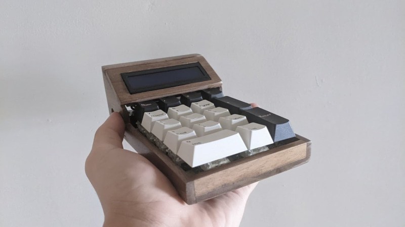
There are certain design aesthetics from every era that manage to survive the fads of their time and live throughout history. Ancient Greek architecture is still drawn upon for design inspiration in modern buildings, the mid-century modern style from the 60s still inspires various designs of consumer goods, and the rounded, clean looking cars from the 90s are still highly desirable qualities in automotive design. For electronics, though, we like this 70s-inspired calculator that [Aaron] recently built.

The calculator hearkens back to the days of calculators like the HP-29C with its large buttons and dot-matrix display. [Aaron] built the case out of various woods with a screen angled towards the user, and it uses a LCD display similar to those found in antique calculators. The brain of the calculator is an Arduino which fits easily into the case, and [Aaron] also built the keyboard from scratch with Cherry MX-style mechanical keys soldered together into a custom shape.

The software to run the calculator is fairly straightforward, but we are most impressed with the woodworking, styling, and keyboard design in this build. [Aaron] is also still ironing out some bugs with the power supply as it uses a DC-DC converter to power the device from a single lithium battery. For those who are more fond of early 2000s graphing calculators instead, be sure to take a look at this graphing calculator arcade cabinet.

Pocket Computer Reminds Us of PDAs

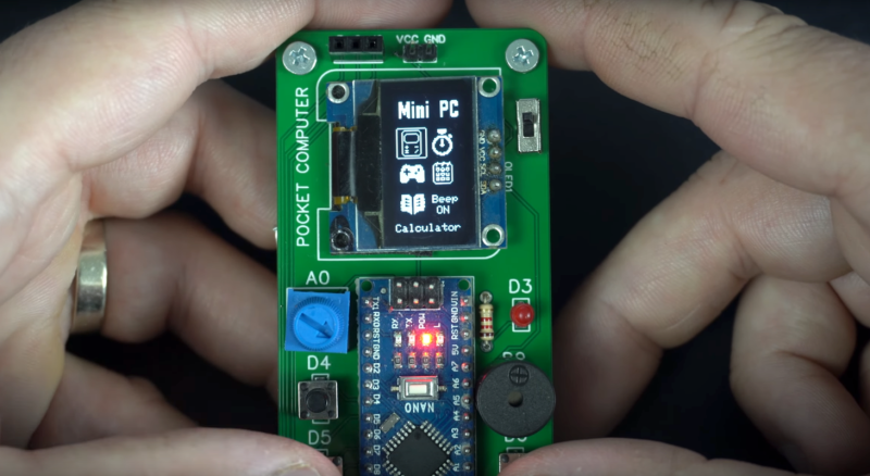
Before smartphones exploded on the scene in the late 00s, there was still a reasonable demand for pocket-sized computers that could do relatively simple computing tasks. Palm Pilots and other PDAs (Personal Digital Assistants) were all the rage in the ’90s and early ’00s, although for cutting-edge tech from that era plenty of these devices had astronomical price tags. This Arduino-based PDA hearkens back to that era, albeit with a much more accessible parts list.

The build is based around an Arudino Nano with an OLED screen and has the five necessary functions for a PDA: calculator, stopwatch, games, phonebook, and a calendar. With all of these components on such a small microcontroller, memory quickly became an issue when using the default libraries. [Danko] uses his own custom libraries in order to make the best use of memory which are all available on the project’s GitHub page. The build also includes a custom PCB to keep the entire pocket computer pocket-sized.

There are some other features packed into this tiny build as well, like the breakout game that can be played with a potentiometer. It’s an impressive build that makes as much use of the microcontroller’s capabilities as is possible, and if you enjoy projects where a microcontroller is used as if it is a PC take a look at this Arduino build with its own command-line interface.

Hack a Day 23 Jun 21:00

Calcuino is an Arduino Calculator

All by itself, a calculator based on an Arduino isn’t necessarily very novel. However, [Volos] has a nice board that, of course, looks like a calculator. There are 16 keys and an LED display. But it seems to us the real value would be using this as a base for other projects.

As an inexpensive development board, it’s handy to have a simple processor with a keyboard and a display. There’s some extra I/O pins and the first example in the video below shows using the setup as a simple organ, for example. We’d love to see an option to replace the LED with an LCD and maybe even some different CPU options, as well.

The board is essentially an Arduino with a standard USB to serial chip and a MAX7219 display driver. Of course, you could breadboard up all of these things, but it wouldn’t be as neat looking. One unusual thing about the keyboard is that it is not multiplexed. Each button has a label that indicates what Arduino pin it connects with. So key 6 connects to pin 6 and pin A2 connects to the key marked =/A2.

With the availability of inexpensive PC boards, we’re seeing many nice designs out there that would be easy to repurpose for other things. For example, we thought this board would easily run the Kim Uno, with some modifications to the I/O routines. Might even be able to work out a clone of an even older computer to fit on the board.

Hack a Day 28 Jun 15:00

21st Century Cheating: WiFi In A Calculator

Obviously, we would never endorse cheating on an exam, but sometimes a device is just too tempting to be left untouched. For [Neutrino], it was an old Casio calculator that happened to have a perfectly sized solar panel to fit a 128×32 OLED as replacement. But since the display won’t do much on its own, he decided to connect it to an ESP8266 and mount it all inside the calculator’s housing, turning it into a spy-worthy, internet-connected cheating device, including a stealthy user interface controlled by magnets instead of physical buttons. (Video, embedded below.)

To achieve the latter, [Neutrino] added two Hall effect sensors and a reed switch inside each end of the calculator. Placing a magnet — possibly hidden in a pen cap — near the reed switch will turn the display on, and placing another magnet near the Hall-effect sensors will navigate through the display’s interface, supporting two inputs with long, short, and multi-tap gestures each. To obtain information through WiFi, the ESP8266 connects to Firebase as backend, allowing to set up predefined content to fetch, as well as a possibility to communicate with your partner(s) in crime through a simple chat program.

As the main idea was to keep visible modifications to a minimum, one shortcoming is that charging the additional battery that powers the whole system would require an additional, external charging circuit. But [Neutrino] had a solution for that as well, and simply exposed two wires to the back, which could easily be mistaken for random solder splatters. And well, of course, requiring WiFi might also be tricky in some situations, so maybe you might want to consider a mobile network upgrade for yourself.

Hack a Day 07 May 12:00

Button, Button, Who’s Got the (One) Button?

We often think that less is more, but what can you do with a device that has only a single button? [Volos] wondered the same thing and he built an Arduino with a single button and a display. After doing some obvious things  (like a counter or stopwatch) he decided to make a calculator.

You can find the source code online and he used a library from GitHub to handle the reaction to single presses, double presses, and long presses. Is it ideal? Probably not. But if you only have a limited amount of space or pins, it can make the difference between a feasible project and one you can’t finish.

His original projects also included a Flappy Bird clone. The OLED display is only 64×48 so that’s not a lot of room. The packaging of the tiny Arduino, the battery, and the display in a good looking case, was pretty impressive. So the device might be usable for something.

Of course, the library will work with any program and there’s no reason you can’t have more than one button and simply multiply their functions with the same strategy. There’s a sample on GitHub that shows how you can create two OneButton objects connected to different hardware devices.

By the way, the little box may have only one button, but it also has a power switch. Turns out, you can use it as an input in certain circumstances. If the OLED display strikes you as too luxurious, try the DUO BINARY.

Crippled Calculator Features Unlocked with Automated Help

[Aguilera Dario] likes his Casio fx-82ES calculator. However, it was missing a few functions, including complex numbers. A Casio fx-991ES has more functions but, of course, costs more. A quick Google revealed that if you press the right buttons, though, you can transform an fx-82ES into an fx-991ES.

Because it is apparently a buffer overflow exploit, the hack involves a lot of keys and once you cycle the power you have to do it again. [Aguilera] realized this would be a good candidate for automation and added a microcontroller to push his buttons. You can see a video of a breadboard version below. He also has a PCB version in the works that should be better integrated.

The automation hardware patches into the button matrix through test pads on the back of the calculator’s PCB. [Aguilera] soldered ribbon cable directly to these pads, then snaked it out through a slot cut into the back of the calculator case where it is terminated with a 0.1″ pin socket. An Arduino Mini is used in the prototype, the next revision will use an ATmega328P on a custom board. The uC interfaces with the button connections using the venerable 4066 chip which is able to act as an analog switch.

The board layout for the PCB version is shown on the project page. There is no word on whether this is meant to be a permanent addition to the calculator, or just plugged in for the exploit and stored away for use the next time power is cycled. Either way, it’s neat to learn about this exploit and a cool challenge to automate it!

If you don’t want to hack up an off-the-shelf calculator, grab some nixie tubes and make your own. Or, if you are short on tubes, try this one.


Filed under: Arduino Hacks

Fun Audio Waveform Generator Is More Than The Sum Of Its Parts

[Joekutz] wanted to re-build an audio-rate function generator project that he found over on Instructables. By itself, the project is very simple: it’s an 8-bit resistor-ladder DAC, a nice enclosure, and the rest is firmware.

[Joekutz] decided this wasn’t enough. He needed an LCD display, a speaker, and one-hertz precision. The LCD display alone is an insane hack. He reverse-engineers a calculator simply to use the display. But instead of mapping each key on the calculator and typing each number in directly, he only taps the four 1, +, =, and clear keys. He can then enter arbitrary numbers by typing in the right number of ones and adding them up. 345 = 111 + 111 + 111 + 11 + 1. In his video, embedded below, he describes this as a “rather stupid” idea. We think it’s hilarious.

The meat of the project is the Arduino-based waveform generator, though. In the second video below, [joekutz] walks through the firmware in detail. If you’d like a simple introduction to DDS, check it out (or read up our more in-depth version).

He also makes custom detents for his potentiometers so that he can enter precise numerical values. These consist of special knobs and spring-clips that work together to turn a normal pot into a rough 8-way (or whatever) switch. Very cool.

So even if you don’t need an R-2R DAC based waveform generator, go check this project out. There’s good ideas at every turn.


Filed under: Arduino Hacks

The Newest Graphing Calculator Game

Certainly everyone remembers passing time in a boring high school class playing games on a graphing calculator. Whether it was a Mario-esque game, Tetris, or BlockDude, there are plenty of games out there for pretty much all of the graphing calculators that exist. [Christopher], [Tim], and their colleagues from Cemetech took their calculator game a little bit farther than we did, and built something that’ll almost surely disrupt whatever class you’re attempting to pay attention in: They built a graphing calculator whac-a-mole game.

This game isn’t the standard whac-a-mole game, though, and it isn’t played on the calculator’s screen. Instead of phyiscal “moles” the game uses LEDs and light sensors enclosed in a box to emulate the function of the moles. In order to whack a mole, the player only needs to interrupt the light beam which can be done with any physical object. The team made extensive use of the ArTICL library which allows graphing calculators to interface with microcontrollers like the MSP432 that they used, and drove the whole thing with a classic TI-84.

This project is a fun way to show what can be done with a graphing calculator and embedded electronics, and it was a big hit at this past year’s World Maker Faire. Calculators are versatile in other ways as well. We’ve seen them built with open hardware and free software, And we’ve even seen them get their own Wi-Fi.


Filed under: handhelds hacks