Posts with «ds1307» label

Tutorial – LED Real Time Clock Temperature Sensor Shield for Arduino

In this tutorial we look at how to use the neat LED Real Time Clock Temperature Sensor Shield for Arduino from PMD Way. That’s a bit of a mouthful, however the shield does offer the following:

  • four digit, seven-segment LED display
  • DS1307 real-time clock IC
  • three buttons
  • four LEDs
  • a active buzzer
  • a light-dependent resistor (LDR)
  • and a thermistor for measuring ambient temperature

The shield also arrives fully-assembled , so you can just plug it into your Arduino Uno or compatible board. Neat, beginners will love that. So let’s get started, by showing how each function can be used – then some example projects. In no particular order…

The buzzer

A high-pitched active buzzer is connected to digital pin D6 – which can be turned on and off with a simple digitalWrite() function. So let’s do that now, for example:

void setup() {
  // buzzer on digital pin 6
  pinMode(6, OUTPUT);
}

// the loop function runs over and over again forever
void loop() {
  digitalWrite(6, HIGH);   // turn the buzzer on (HIGH is the voltage level)
  delay(1000);                       // wait for a second
  digitalWrite(6, LOW);    // turn the buzzer off by making the voltage LOW
  delay(1000);                       // wait for a second
}

If there is a white sticker over your buzzer, remove it before uploading the sketch. Now for a quick video demonstration. Turn down your volume before playback.

The LEDs

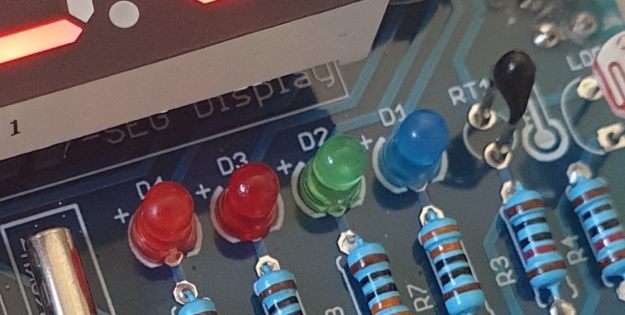
Our shield has four LEDs, as shown below:

They’re labelled D1 through to D4, with D1 on the right-hand side. They are wired to digital outputs D2, D3, D4 and D5 respectively. Again, they can be used with digitalWrite() – so let’s do that now with a quick demonstration of some blinky goodness. Our sketch turns the LEDs on and off in sequential order. You can change the delay by altering the variable x:

void setup() {
  // initialize digital pin LED_BUILTIN as an output.
  pinMode(2, OUTPUT); // LED 1
  pinMode(3, OUTPUT); // LED 2
  pinMode(4, OUTPUT); // LED 3
  pinMode(5, OUTPUT); // LED 4
}

int x = 200;

void loop() {
  digitalWrite(2, HIGH);    // turn on LED1
  delay(x);
  digitalWrite(2, LOW);    // turn off LED1. Process repeats for the other three LEDs
  digitalWrite(3, HIGH);
  delay(x);
  digitalWrite(3, LOW);
  digitalWrite(4, HIGH);
  delay(x);
  digitalWrite(4, LOW);
  digitalWrite(5, HIGH);
  delay(x);
  digitalWrite(5, LOW);
}

And in action:

The Buttons

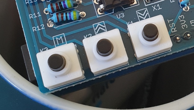
It is now time to pay attention to the three large buttons on the bottom-left of the shield. They look imposing however are just normal buttons, and from right-to-left are connected to digital pins D9, D10 and D11:

They are, however, wired without external pull-up or pull-down resistors so when initialising them in your Arduino sketch you need to activate the digital input’s internal pull-up resistor inside the microcontroller using:

pinMode(pin, INPUT_PULLUP);

Due to this, buttons are by default HIGH when not pressed. So when you press a button, they return LOW. The following sketch demonstrates the use of the buttons by lighting LEDs when pressed:

void setup() {
  // initalise digital pins for LEDs as outputs
  pinMode(2, OUTPUT); // LED 1
  pinMode(3, OUTPUT); // LED 2
  pinMode(4, OUTPUT); // LED 3

  // initalise digital pins for buttons as inputs
  // and initialise internal pullups
  pinMode(9, INPUT_PULLUP); // button K1
  pinMode(10, INPUT_PULLUP); // button K2
  pinMode(11, INPUT_PULLUP); // button K3
}

void loop()
{
  if (digitalRead(9) == LOW)
  {
    digitalWrite(2, HIGH);
    delay(10);
    digitalWrite(2, LOW);
  }

  if (digitalRead(10) == LOW)
  {
    digitalWrite(3, HIGH);
    delay(10);
    digitalWrite(3, LOW);
  }

  if (digitalRead(11) == LOW)
  {
    digitalWrite(4, HIGH);
    delay(10);
    digitalWrite(4, LOW);
  }
}

You can see these in action via the following video:

The Numerical LED Display

Our shield has a nice red four-digit, seven-segment LED clock display. We call it a clock display as there are colon LEDs between the second and third digit, just as a digital clock would usually have:

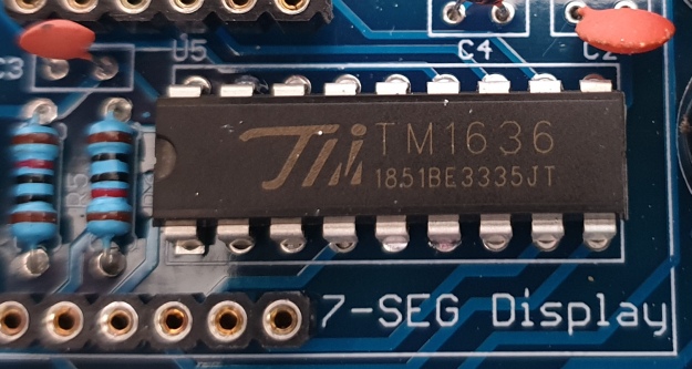
The display is controlled by a special IC, the Titan Micro TM1636:

The TM1636 itself is an interesting part, so we’ll explain that in a separate tutorial in the near future. For now, back to the shield.

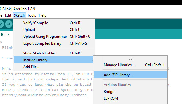
To control the LED display we need to install an Arduino library. In fact the shield needs four, so you can install them all at once now. Download the .zip file from here. Then expand that into your local download directory – it contains four library folders. You can then install them one at a time using the Arduino IDE’s Sketch > Include library > Add .zip library… command:
The supplied library offers five functions used to control the display.

.num(x);

…this displays a positive integer (whole number) between 0 and 9999.

.display(p,d);

… this shows a digit d in location p (locations from left to right are 3, 2, 1, 0)

.time(h,m)

… this is used to display time data (hours, minutes) easily. h is hours, m is minutes

.pointOn();
.pointOff();

… these turn the colon on … and off. And finally:

.clear();

… which clears the display to all off. At the start of the sketch, we need to use the library and initiate the instance of the display by inserting the following lines:

#include <TTSDisplay.h>
TTSDisplay rtcshield;

Don’t panic – the following sketch demonstrates the five functions described above:

#include <TTSDisplay.h>
TTSDisplay rtcshield;

int a = 0;
int b = 0;

void setup() {}

void loop()
{
  // display some numbers
  for (a = 4921; a < 5101; a++)
  {
    rtcshield.num(a);
    delay(10);
  }

  // clear display
  rtcshield.clear();

  // display individual digits
  for (a = 3; a >= 0; --a)
  {
    rtcshield.display(a, a);
    delay(1000);
    rtcshield.clear();
  }
  for (a = 3; a >= 0; --a)
  {
    rtcshield.display(a, a);
    delay(1000);
    rtcshield.clear();
  }

  // turn the colon and off
  for (a = 0; a < 5; a++)
  {
    rtcshield.pointOn();
    delay(500);
    rtcshield.pointOff();
    delay(500);
  }

  // demo the time display function
  rtcshield.pointOn();
  rtcshield.time(11, 57);
  delay(1000);
  rtcshield.time(11, 58);
  delay(1000);
  rtcshield.time(11, 59);
  delay(1000);
  rtcshield.time(12, 00);
  delay(1000);
}

And you can see it in action through the video below:

The LDR (Light Dependent Resistor)

LDRs are useful for giving basic light level measurements, and our shield has one connected to analog input pin A1. It’s the two-legged item with the squiggle on top as shown below:
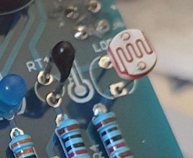
The resistance of LDRs change with light levels – the greater the light, the less the resistance. Thus by measuring the voltage of a current through the LDR with an analog input pin – you can get a numerical value proportional to the ambient light level. And that’s just what the following sketch does:

#include <TTSDisplay.h>
TTSDisplay rtcshield;

int a = 0;

void setup() {}
void loop()
{
  // read value of analog input
  a = analogRead(A1);
  // show value on display
  rtcshield.num(a);
  delay(100);
}

The Thermistor

A thermistor is a resistor whose resistance is relative to the ambient temperature. As the temperature increases, their resistance decreases. It’s the black part to the left of the LDR in the image below:

We can use this relationship between temperature and resistance to determine the ambient temperature. To keep things simple we won’t go into the theory – instead, just show you how to get a reading.

The thermistor circuit on our shield has the output connected to analog input zero, and we can use the library installed earlier to take care of the mathematics. Which just leaves us with the functions.

At the start of the sketch, we need to use the library and initiate the instance of the thermistor by inserting the following lines:

#include <TTSTemp.h>
TTSTemp temp;

… then use the following which returns a positive integer containing the temperature (so no freezing cold environments):

.get();

For our example, we’ll get the temperature and show it on the numerical display:

#include <TTSDisplay.h>
#include <TTSTemp.h>

TTSTemp temp;
TTSDisplay rtcshield;

int a = 0;

void setup() {}

void loop() {

  a = temp.get();
  rtcshield.num(a);
  delay(500);
}

And our thermometer in action. No video this time… a nice 24 degrees C in the office:

The Real-Time Clock 

Our shield is fitted with a DS1307 real-time clock IC circuit and backup battery holder. If you insert a CR1220 battery, the RTC will remember the settings even if you remove the shield from the Arduino or if there’s a power blackout, board reset etc:

The DS1307 is incredibly popular and used in many projects and found on many inexpensive breakout boards. We have a separate tutorial on how to use the DS1307, so instead of repeating ourselves – please visit our specific DS1307 Arduino tutorial, then return when finished.

Where to from here? 

We can image there are many practical uses for this shield, which will not only improve your Arduino coding skills but also have some useful applications. An example is given below, that you can use for learning or fun.

Temperature Alarm

This projects turns the shield into a temperature monitor – you can select a lower and upper temperature, and if the temperature goes outside that range the buzzer can sound until you press it.

Here’s the sketch:

#include <TTSDisplay.h>
#include <TTSTemp.h>

TTSTemp temp;
TTSDisplay rtcshield;

boolean alarmOnOff = false;
int highTemp = 40;
int lowTemp = 10;
int currentTemp;

void LEDsoff()
{
  // function to turn all alarm high/low LEDs off
  digitalWrite(2, LOW);
  digitalWrite(4, LOW);
}

void setup() {
  // initalise digital pins for LEDs and buzzer as outputs
  pinMode(2, OUTPUT); // LED 1
  pinMode(3, OUTPUT); // LED 2
  pinMode(4, OUTPUT); // LED 3
  pinMode(5, OUTPUT); // LED 4
  pinMode(6, OUTPUT); // buzzer

  // initalise digital pins for buttons as inputs
  // and initialise internal pullups
  pinMode(9, INPUT_PULLUP); // button K1
  pinMode(10, INPUT_PULLUP); // button K2
  pinMode(11, INPUT_PULLUP); // button K3
}

void loop()
{
  // get current temperature
  currentTemp = temp.get();

  // if current temperature is within set limts
  // show temperature on display

  if (currentTemp >= lowTemp || currentTemp <= highTemp)
    // if ambient temperature is less than high boundary
    // OR if ambient temperature is grater than low boundary
    // all is well
  {
    LEDsoff(); // turn off LEDs
    rtcshield.num(currentTemp);
  }

  // if current temperature is above set high bounday, show red LED and
  // show temperature on display
  // turn on buzzer if alarm is set to on (button K3)

  if (currentTemp > highTemp)
  {
    LEDsoff(); // turn off LEDs
    digitalWrite(4, HIGH); // turn on red LED
    rtcshield.num(currentTemp);
    if (alarmOnOff == true) {
      digitalWrite(6, HIGH); // buzzer on }
    }
  }

  // if current temperature is below set lower boundary, show blue LED and
  // show temperature on display
  // turn on buzzer if alarm is set to on (button K3)

  if (currentTemp < lowTemp)
  {
    LEDsoff(); // turn off LEDs
    digitalWrite(2, HIGH); // turn on blue LED
    rtcshield.num(currentTemp);
    if (alarmOnOff == true)
    {
      digitalWrite(6, HIGH); // buzzer on }
    }
  }
  // --------turn alarm on or off-----------------------------------------------------
  if (digitalRead(11) == LOW) // turn alarm on or off
  {
    alarmOnOff = !alarmOnOff;
    if (alarmOnOff == 0) {
      digitalWrite(6, LOW); // turn off buzzer
      digitalWrite(5, LOW); // turn off alarm on LED
    }
    // if alarm is set to on, turn LED on to indicate this
    if (alarmOnOff == 1)
    {
      digitalWrite(5, HIGH);
    }
    delay(300); // software debounce
  }
  // --------set low temperature------------------------------------------------------
  if (digitalRead(10) == LOW) // set low temperature. If temp falls below this value, activate alarm
  {
    // clear display and turn on blue LED to indicate user is setting lower boundary
    rtcshield.clear();
    digitalWrite(2, HIGH); // turn on blue LED
    rtcshield.num(lowTemp);

    // user can press buttons K2 and K1 to decrease/increase lower boundary.
    // once user presses button K3, lower boundary is locked in and unit goes
    // back to normal state

    while (digitalRead(11) != LOW)
      // repeat the following code until the user presses button K3
    {
      if (digitalRead(10) == LOW) // if button K2 pressed
      {
        --lowTemp; // subtract one from lower boundary
        // display new value. If this falls below zero, won't display. You can add checks for this yourself :)
        rtcshield.num(lowTemp);
      }
      if (digitalRead(9) == LOW) // if button K3 pressed
      {
        lowTemp++; // add one to lower boundary
        // display new value. If this exceeds 9999, won't display. You can add checks for this yourself :)
        rtcshield.num(lowTemp);
      }
      delay(300); // for switch debounce
    }
    digitalWrite(2, LOW); // turn off blue LED
  }
  // --------set high temperature-----------------------------------------------------
  if (digitalRead(9) == LOW) // set high temperature. If temp exceeds this value, activate alarm
  {

    // clear display and turn on red LED to indicate user is setting lower boundary
    rtcshield.clear();
    digitalWrite(4, HIGH); // turn on red LED
    rtcshield.num(highTemp);

    // user can press buttons K2 and K1 to decrease/increase upper boundary.
    // once user presses button K3, upper boundary is locked in and unit goes
    // back to normal state

    while (digitalRead(11) != LOW)
      // repeat the following code until the user presses button K3
    {
      if (digitalRead(10) == LOW) // if button K2 pressed
      {
        --highTemp; // subtract one from upper boundary
        // display new value. If this falls below zero, won't display. You can add checks for this yourself :)
        rtcshield.num(highTemp);
      }
      if (digitalRead(9) == LOW) // if button K3 pressed
      {
        highTemp++; // add one to upper boundary
        // display new value. If this exceeds 9999, won't display. You can add checks for this yourself :)
        rtcshield.num(highTemp);
      }
      delay(300); // for switch debounce
    }
    digitalWrite(4, LOW); // turn off red LED
  }
}

Operating instructions:

  • To set lower temperature, – press button K2. Blue LED turns on. Use buttons K2 and K1 to select temperature, then press K3 to lock it in. Blue LED turns off.
  • To set upper temperature – press button K1. Red LED turns on. Use buttons K2 and K1 to select temperature, then press K3 to lock it in. Red LED turns off.
  • If temperature drops below lower or exceeds upper temperature, the blue or red LED will come on.
  • You can have the buzzer sound when the alarm activates – to do this, press K3. When the buzzer mode is on, LED D4 will be on. You can turn buzzer off after it activates by pressing K3.
  • Display will show ambient temperature during normal operation.

You can see this in action via the video below:

Conclusion

This is a fun and useful shield – especially for beginners. It offers a lot of fun and options without any difficult coding or soldering – it’s easy to find success with the shield and increase your motivation to learn more and make more.

You can be serious with a clock, or annoy people with the buzzer. And at the time of writing you can have one for US$14.95, delivered. So go forth and create something.

A little research has shown that this shield was based from a product by Seeed, who discontinued it from sale. I’d like to thank them for the library.

This post brought to you by pmdway.com – everything for makers and electronics enthusiasts, with free delivery worldwide.

To keep up to date with new posts at tronixstuff.com, please subscribe to the mailing list in the box on the right, or follow us on twitter @tronixstuff.

Arduino Tachometer Clock Fires on All Cylinders

We’re certainly no strangers to unique timepieces around these parts. For whatever reason, hackers are obsessed with finding new and interesting ways of displaying the time. Not that we’re complaining, of course. We’re just as excited to see the things as they are to build them. With the assumption that you’re just as enamored with these oddball chronometers as we are, we present to you this fantastic digital tachometer clock created by [mrbigbusiness].

The multi-function digital gauge itself is an aftermarket unit which [mrbigbusiness] says you can get online for as little as $20 from some sites. All he needed to do was figure out how to get his Arduino to talk to it, and come up with some interesting way to hold it at an appropriate viewing angle. The mass of wires coming out of the back of the gauge might look intimidating, but thanks to his well documented code it shouldn’t be too hard to follow in his footsteps if you were so inclined.

Hours are represented by the analog portion of the gauge, and the minutes shown digitally were the speed would normally be displayed. This allows for a very cool blending of the classic look of an analog clock with the accuracy of digital. He’s even got it set up so the fuel indicator will fill up as the current minute progresses. The code also explains how to use things like the gear and high beam indicators, so there’s a lot of room for customization and interesting data visualizations. For instance, it would be easy to scrap the whole clock idea and use this gauge as a system monitor with some modifications to the code [mrbigbusiness] has provided.

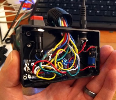
The gauge is mounted to a small project box with some 3D printed brackets and bits of metal rod, complete with a small section of flexible loom to cover up all the wires. Overall it looks very slick and futuristic without abandoning its obvious automotive roots. Inside the base [mrbigbusiness] has an Arduino Nano, a DS1307 RTC connected via I2C, a voltage regulator, and a push button to set the time. It’s a perfectly reasonable layout, though we wonder if it couldn’t be simplified by using an ESP8266 and pulling the time down with NTP.

We’ve seen gauges turned into a timepiece before, but we have to admit that this is probably the most practical realization we’ve seen of the idea yet. Of course if you want to outfit the garage with something a bit more authentic, you can always repurpose a Porsche brake rotor.

Modernizing a 170 year old Antique Grandfather Clock

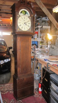
Frankly, we let out a yelp of despair when we read this in the tip line “Antique Grandfather clock with Arduino insides“! But before you too roll your eyes, groan, or post snark, do check out [David Henshaw]’s amazing blog post on how he spent almost eight months working on the conversion.

Before you jump to any conclusions about his credentials, we must point out that [David] is an ace hacker who has been building electronic clocks for a long time. In this project, he takes the antique grandfather clock from 1847, and puts inside it a new movement built from Meccano pieces, stepper motors, hall sensors, LEDs, an Arduino and lots of breadboard and jumper wires while making sure that it still looks and sounds as close to the original as possible.

He starts off by building a custom electro-mechanical clock movement, and since he’s planning as he progresses, meccano, breadboard and jumper wires were the way to go. Hot glue helps preserve sanity by keeping all the jumper wires in place. To interface with all of the peripherals in the clock, he decided to use a bank of shift registers driven from a regular Arduino Uno. The more expensive DS3231 RTC module ensures better accuracy compared to the cheaper DS1307 or similar clones. A bank of RGB LEDs acts as an annunciator panel inside the clock to help provide various status indications. The mechanical movement itself went through several iterations to get the time display working with a smooth movement of the hands. Besides displaying time, [David] also added a moon phase indicator dial. A five-rod chime is struck using a stepper motor driven cam and a separate solenoid is used to pull and release three chime hammers simultaneously to generate the loud gong sounds.

And here’s the amazing part – he did all of this before laying his hands on the actual grandfather clock – which was shipped to him in California from an antique clock specialist in England and took two months to arrive. [David] ordered just the clock housing, dial/face and external parts, with none of the original inner mechanism. Once he received it, his custom clock-work assembly needed some more tweaking to get all the positions right for the various hands and dials. A clock like this without its typical “ticktock” sound would be pretty lame, so [David] used a pair of solenoids to provide the sound effect, with each one being turned on for a different duration to produce the characteristic ticktock.

At the end of eight months, the result – christened Judge – was pretty satisfying. Check the video below to judge the Judge for yourself. If you would like to see some more of [David]’s clockwork, check out Dottie the Flip Dot Clock and A Reel to Reel Clock.


Filed under: Arduino Hacks, clock hacks

X Marks the Clock

There’s no shortage of Arduino-based clocks around. [Mr_fid’s] clock, though, gets a second look because it is very unique looking. Then it gets a third look because it would be very difficult to read for the uninitiated.

The clock uses three Xs made of LEDs. There is one X for the hours (this is a 24-hour clock), another for the minutes, and one for the seconds. The left side of each X represents the tens’ digit of the number, while the right-side is the units.

But wait… even with two segments on each side of the X, that only allows for numbers from 0 to 3 in binary, right? [Mr_fid] uses another dimension–color–to get around that limitation. Although he calls this a binary clock, it is more accurately a binary-coded-decimal (BCD) clock. Red LEDs represent the numbers one to three. Green LEDs are four to six. Two blue segments represent seven to nine. It sounds complicated, but if you watch the video, below, it will make sense.

This isn’t [Mr_fid’s] first clock. He is using a DS1307 real time clock module to make up for the Arduino’s tendency to drift. Even if you aren’t interested in the clock, the mounting of the LEDs with plastic–and the issues he had isolating them from each other–might come in handy in other displays.

We’ve seen a lot of Arduino clocks over the years, including some that talk. We’ve even seen some that qualify as interactive furniture, whatever that is.


Filed under: Arduino Hacks, clock hacks
Hack a Day 13 Jan 03:00

Tutorial – Using DS1307 and DS3231 Real-time Clock Modules with Arduino

We keep getting requests on how to use DS1307 and DS3231 real-time clock modules with Arduino from various sources – so this is the first of a two part tutorial on how to use them. For this Arduino tutorial we have  two real-time clock modules to use, one based on the Maxim DS1307:

and another based on the DS3231:

There are two main differences between the ICs on the real-time clock modules, which is the accuracy of the time-keeping. The DS1307 used in the first module works very well, however the external temperature can affect the frequency of the oscillator circuit which drives the DS1307’s internal counter.

This may sound like a problem, however will usually result with the clock being off by around five or so minutes per month. The DS3231 is much more accurate, as it has an internal oscillator which isn’t affected by external factors – and thus is accurate down to a few minutes per year at the most. If you have a DS1307 module- don’t feel bad, it’s still a great value board and will serve you well.

With both of the modules, a backup battery is installed when you receive them from Tronixlabs, however these are an inexpensive variety and shouldn’t be relied on for more than twelve months. If you’re going to install the module in a more permanent project, its’ a good idea to buy a new CR2023 battery and fit it to the module.

Along with keeping track of the time and date, these modules also have a small EEPROM, an alarm function (DS3231 only) and the ability to generate a square-wave of various frequencies – all of which will be the subject of a second tutorial.

Connecting your module to an Arduino

Both modules use the I2C bus, which makes connection very easy. If you’re not sure about the I2C bus and Arduino, check out the I2C tutorials (chapters 20 and 21), or review chapter seventeen of my book “Arduino Workshop“.

Moving on – first you will need to identify which pins on your Arduino or compatible boards are used for the I2C bus – these will be knows as SDA (or data) and SCL (or clock). On Arduino Uno or compatible boards, these pins are A4 and A5 for data and clock:

If you’re using an Arduino Mega the pins are D20 and D21 for data and clock:

If you’re using an Pro Mini-compatible the pins are A4 and A5 for data and clock, which are parallel to the main pins, as shown below:

DS1307 module

If you have the DS1307 module you will need to solder the wires to the board, or solder on some inline header pins so you can use jumper wires. Then connect the SCL and SDA pins to your Arduino, and the Vcc pin to the 5V pin and GND to GND.

DS3231 module

Connecting this module is easy as header pins are installed on the board at the factory. You can simply run jumper wires again from SCL and SDA to the Arduino and again from the module’s Vcc and GND pins to your board’s 5V or 3.3.V and GND. However these are duplicated on the other side for soldering your own wires.

Both of these modules have the required pull-up resistors, so you don’t need to add your own. Like all devices connected to the I2C bus, try and keep the length of the SDA and SCL wires to a minimum.

Reading and writing the time from your RTC Module

Once you have wired up your RTC module. enter and upload the following sketch. Although the notes and functions in the sketch refer only to the DS3231, the code also works with the DS1307.

#include "Wire.h"
#define DS3231_I2C_ADDRESS 0x68
// Convert normal decimal numbers to binary coded decimal
byte decToBcd(byte val)
{
  return( (val/10*16) + (val%10) );
}
// Convert binary coded decimal to normal decimal numbers
byte bcdToDec(byte val)
{
  return( (val/16*10) + (val%16) );
}
void setup()
{
  Wire.begin();
  Serial.begin(9600);
  // set the initial time here:
  // DS3231 seconds, minutes, hours, day, date, month, year
  // setDS3231time(30,42,21,4,26,11,14);
}
void setDS3231time(byte second, byte minute, byte hour, byte dayOfWeek, byte
dayOfMonth, byte month, byte year)
{
  // sets time and date data to DS3231
  Wire.beginTransmission(DS3231_I2C_ADDRESS);
  Wire.write(0); // set next input to start at the seconds register
  Wire.write(decToBcd(second)); // set seconds
  Wire.write(decToBcd(minute)); // set minutes
  Wire.write(decToBcd(hour)); // set hours
  Wire.write(decToBcd(dayOfWeek)); // set day of week (1=Sunday, 7=Saturday)
  Wire.write(decToBcd(dayOfMonth)); // set date (1 to 31)
  Wire.write(decToBcd(month)); // set month
  Wire.write(decToBcd(year)); // set year (0 to 99)
  Wire.endTransmission();
}
void readDS3231time(byte *second,
byte *minute,
byte *hour,
byte *dayOfWeek,
byte *dayOfMonth,
byte *month,
byte *year)
{
  Wire.beginTransmission(DS3231_I2C_ADDRESS);
  Wire.write(0); // set DS3231 register pointer to 00h
  Wire.endTransmission();
  Wire.requestFrom(DS3231_I2C_ADDRESS, 7);
  // request seven bytes of data from DS3231 starting from register 00h
  *second = bcdToDec(Wire.read() & 0x7f);
  *minute = bcdToDec(Wire.read());
  *hour = bcdToDec(Wire.read() & 0x3f);
  *dayOfWeek = bcdToDec(Wire.read());
  *dayOfMonth = bcdToDec(Wire.read());
  *month = bcdToDec(Wire.read());
  *year = bcdToDec(Wire.read());
}
void displayTime()
{
  byte second, minute, hour, dayOfWeek, dayOfMonth, month, year;
  // retrieve data from DS3231
  readDS3231time(&second, &minute, &hour, &dayOfWeek, &dayOfMonth, &month,
  &year);
  // send it to the serial monitor
  Serial.print(hour, DEC);
  // convert the byte variable to a decimal number when displayed
  Serial.print(":");
  if (minute<10)
  {
    Serial.print("0");
  }
  Serial.print(minute, DEC);
  Serial.print(":");
  if (second<10)
  {
    Serial.print("0");
  }
  Serial.print(second, DEC);
  Serial.print(" ");
  Serial.print(dayOfMonth, DEC);
  Serial.print("/");
  Serial.print(month, DEC);
  Serial.print("/");
  Serial.print(year, DEC);
  Serial.print(" Day of week: ");
  switch(dayOfWeek){
  case 1:
    Serial.println("Sunday");
    break;
  case 2:
    Serial.println("Monday");
    break;
  case 3:
    Serial.println("Tuesday");
    break;
  case 4:
    Serial.println("Wednesday");
    break;
  case 5:
    Serial.println("Thursday");
    break;
  case 6:
    Serial.println("Friday");
    break;
  case 7:
    Serial.println("Saturday");
    break;
  }
}
void loop()
{
  displayTime(); // display the real-time clock data on the Serial Monitor,
  delay(1000); // every second
}

There may be a lot of code, however it breaks down well into manageable parts.

It first includes the Wire library, which is used for I2C bus communication, followed by defining the bus address for the RTC as 0x68. These are followed by two functions that convert decimal numbers to BCD (binary-coded decimal) and vice versa. These are necessary as the RTC ICs work in BCD not decimal.

The function setDS3231time() is used to set the clock. Using it is very easy, simple insert the values from year down to second, and the RTC will start from that time. For example if you want to set the following date and time – Wednesday November 26, 2014 and 9:42 pm and 30 seconds – you would use:

setDS3231time(30,42,21,4,26,11,14);

Note that the time is set using 24-hour time, and the fourth paramter is the “day of week”. This falls between 1 and 7 which is Sunday to Saturday respectively. These parameters are byte values if you are subsituting your own variables.

Once you have run the function once it’s wise to prefix it with // and upload your code again, so it will not reset the time once the power has been cycled or micrcontroller reset.

Reading the time form your RTC Is just as simple, in fact the process can be followed neatly inside the function displayTime(). You will need to define seven byte variables to store the data from the RTC, and these are then inserted in the function readDS3231time().

For example if your variables are:

byte second, minute, hour, dayOfWeek, dayOfMonth, month, year;

… you would refresh them with the current data from the RTC by using:

readDS3232time(&second, &minute, &hour, &dayOfWeek, &dayOfMonth, &month, &year);

Then you can use the variables as you see fit, from sending the time and date to the serial monitor as the example sketch does – to converting the data into a suitable form for all sorts of output devices.

Just to check everything is working, enter the appropriate time and date into the demonstration sketch, upload it, comment out the setDS3231time() function and upload it again. Then open the serial monitor, and you should be provided with a running display of the current time and date, for example:

From this point you now have the software tools to set data to and retrieve it from your real-time clock module, and we hope you have an understanding of how to use these inexpensive modules.

You can learn more about the particular real-time clock ICs from the manufacturer’s website – DS1307 and DS3231.

And if you enjoyed this article, or want to introduce someone else to the interesting world of Arduino – check out my book (now in a fourth printing!) “Arduino Workshop”.

Have fun and keep checking into tronixstuff.com. Why not follow things on twitterGoogle+, subscribe  for email updates or RSS using the links on the right-hand column, or join our forum – dedicated to the projects and related items on this website.

The post Tutorial – Using DS1307 and DS3231 Real-time Clock Modules with Arduino appeared first on tronixstuff.

Tronixstuff 01 Dec 01:43

Tutorial – Using DS1307 and DS3231 Real-time Clock Modules with Arduino

We keep getting requests on how to use DS1307 and DS3231 real-time clock modules with Arduino from various sources – so this is the first of a two part tutorial on how to use them. For this Arduino tutorial we have  two real-time clock modules to use, one based on the Maxim DS1307:

and another based on the DS3231:

There are two main differences between the ICs on the real-time clock modules, which is the accuracy of the time-keeping. The DS1307 used in the first module works very well, however the external temperature can affect the frequency of the oscillator circuit which drives the DS1307’s internal counter.

This may sound like a problem, however will usually result with the clock being off by around five or so minutes per month. The DS3231 is much more accurate, as it has an internal oscillator which isn’t affected by external factors – and thus is accurate down to a few minutes per year at the most. If you have a DS1307 module- don’t feel bad, it’s still a great value board and will serve you well.

With both of the modules, a backup battery is installed when you receive them from Tronixlabs, however these are an inexpensive variety and shouldn’t be relied on for more than twelve months. If you’re going to install the module in a more permanent project, it’s a good idea to buy a new CR2032 battery and fit it to the module.

Along with keeping track of the time and date, these modules also have a small EEPROM, an alarm function (DS3231 only) and the ability to generate a square-wave of various frequencies – all of which will be the subject of a second tutorial.

Connecting your module to an Arduino

Both modules use the I2C bus, which makes connection very easy. If you’re not sure about the I2C bus and Arduino, check out the I2C tutorials (chapters 20 and 21), or review chapter seventeen of my book “Arduino Workshop“.

Moving on – first you will need to identify which pins on your Arduino or compatible boards are used for the I2C bus – these will be knows as SDA (or data) and SCL (or clock). On Arduino Uno or compatible boards, these pins are A4 and A5 for data and clock:

If you’re using an Arduino Mega the pins are D20 and D21 for data and clock:

If you’re using an Pro Mini-compatible the pins are A4 and A5 for data and clock, which are parallel to the main pins, as shown below:

DS1307 module

If you have the DS1307 module you will need to solder the wires to the board, or solder on some inline header pins so you can use jumper wires. Then connect the SCL and SDA pins to your Arduino, and the Vcc pin to the 5V pin and GND to GND.

DS3231 module

Connecting this module is easy as header pins are installed on the board at the factory. You can simply run jumper wires again from SCL and SDA to the Arduino and again from the module’s Vcc and GND pins to your board’s 5V or 3.3.V and GND. However these are duplicated on the other side for soldering your own wires.

Both of these modules have the required pull-up resistors, so you don’t need to add your own. Like all devices connected to the I2C bus, try and keep the length of the SDA and SCL wires to a minimum.

Reading and writing the time from your RTC Module

Once you have wired up your RTC module. enter and upload the following sketch. Although the notes and functions in the sketch refer only to the DS3231, the code also works with the DS1307.

#include "Wire.h"
#define DS3231_I2C_ADDRESS 0x68
// Convert normal decimal numbers to binary coded decimal
byte decToBcd(byte val)
{
  return( (val/10*16) + (val%10) );
}
// Convert binary coded decimal to normal decimal numbers
byte bcdToDec(byte val)
{
  return( (val/16*10) + (val%16) );
}
void setup()
{
  Wire.begin();
  Serial.begin(9600);
  // set the initial time here:
  // DS3231 seconds, minutes, hours, day, date, month, year
  // setDS3231time(30,42,21,4,26,11,14);
}
void setDS3231time(byte second, byte minute, byte hour, byte dayOfWeek, byte
dayOfMonth, byte month, byte year)
{
  // sets time and date data to DS3231
  Wire.beginTransmission(DS3231_I2C_ADDRESS);
  Wire.write(0); // set next input to start at the seconds register
  Wire.write(decToBcd(second)); // set seconds
  Wire.write(decToBcd(minute)); // set minutes
  Wire.write(decToBcd(hour)); // set hours
  Wire.write(decToBcd(dayOfWeek)); // set day of week (1=Sunday, 7=Saturday)
  Wire.write(decToBcd(dayOfMonth)); // set date (1 to 31)
  Wire.write(decToBcd(month)); // set month
  Wire.write(decToBcd(year)); // set year (0 to 99)
  Wire.endTransmission();
}
void readDS3231time(byte *second,
byte *minute,
byte *hour,
byte *dayOfWeek,
byte *dayOfMonth,
byte *month,
byte *year)
{
  Wire.beginTransmission(DS3231_I2C_ADDRESS);
  Wire.write(0); // set DS3231 register pointer to 00h
  Wire.endTransmission();
  Wire.requestFrom(DS3231_I2C_ADDRESS, 7);
  // request seven bytes of data from DS3231 starting from register 00h
  *second = bcdToDec(Wire.read() & 0x7f);
  *minute = bcdToDec(Wire.read());
  *hour = bcdToDec(Wire.read() & 0x3f);
  *dayOfWeek = bcdToDec(Wire.read());
  *dayOfMonth = bcdToDec(Wire.read());
  *month = bcdToDec(Wire.read());
  *year = bcdToDec(Wire.read());
}
void displayTime()
{
  byte second, minute, hour, dayOfWeek, dayOfMonth, month, year;
  // retrieve data from DS3231
  readDS3231time(&second, &minute, &hour, &dayOfWeek, &dayOfMonth, &month,
  &year);
  // send it to the serial monitor
  Serial.print(hour, DEC);
  // convert the byte variable to a decimal number when displayed
  Serial.print(":");
  if (minute<10)
  {
    Serial.print("0");
  }
  Serial.print(minute, DEC);
  Serial.print(":");
  if (second<10)
  {
    Serial.print("0");
  }
  Serial.print(second, DEC);
  Serial.print(" ");
  Serial.print(dayOfMonth, DEC);
  Serial.print("/");
  Serial.print(month, DEC);
  Serial.print("/");
  Serial.print(year, DEC);
  Serial.print(" Day of week: ");
  switch(dayOfWeek){
  case 1:
    Serial.println("Sunday");
    break;
  case 2:
    Serial.println("Monday");
    break;
  case 3:
    Serial.println("Tuesday");
    break;
  case 4:
    Serial.println("Wednesday");
    break;
  case 5:
    Serial.println("Thursday");
    break;
  case 6:
    Serial.println("Friday");
    break;
  case 7:
    Serial.println("Saturday");
    break;
  }
}
void loop()
{
  displayTime(); // display the real-time clock data on the Serial Monitor,
  delay(1000); // every second
}

There may be a lot of code, however it breaks down well into manageable parts.

It first includes the Wire library, which is used for I2C bus communication, followed by defining the bus address for the RTC as 0x68. These are followed by two functions that convert decimal numbers to BCD (binary-coded decimal) and vice versa. These are necessary as the RTC ICs work in BCD not decimal.

The function setDS3231time() is used to set the clock. Using it is very easy, simple insert the values from year down to second, and the RTC will start from that time. For example if you want to set the following date and time – Wednesday November 26, 2014 and 9:42 pm and 30 seconds – you would use:

setDS3231time(30,42,21,4,26,11,14);

Note that the time is set using 24-hour time, and the fourth paramter is the “day of week”. This falls between 1 and 7 which is Sunday to Saturday respectively. These parameters are byte values if you are subsituting your own variables.

Once you have run the function once it’s wise to prefix it with // and upload your code again, so it will not reset the time once the power has been cycled or micrcontroller reset.

Reading the time form your RTC Is just as simple, in fact the process can be followed neatly inside the function displayTime(). You will need to define seven byte variables to store the data from the RTC, and these are then inserted in the function readDS3231time().

For example if your variables are:

byte second, minute, hour, dayOfWeek, dayOfMonth, month, year;

… you would refresh them with the current data from the RTC by using:

readDS3232time(&second, &minute, &hour, &dayOfWeek, &dayOfMonth, &month, &year);

Then you can use the variables as you see fit, from sending the time and date to the serial monitor as the example sketch does – to converting the data into a suitable form for all sorts of output devices.

Just to check everything is working, enter the appropriate time and date into the demonstration sketch, upload it, comment out the setDS3231time() function and upload it again. Then open the serial monitor, and you should be provided with a running display of the current time and date, for example:

From this point you now have the software tools to set data to and retrieve it from your real-time clock module, and we hope you have an understanding of how to use these inexpensive modules.

You can learn more about the particular real-time clock ICs from the manufacturer’s website – DS1307 and DS3231.

And if you enjoyed this article, or want to introduce someone else to the interesting world of Arduino – check out my book (now in a fourth printing!) “Arduino Workshop”.

Have fun and keep checking into tronixstuff.com. Why not follow things on twitterGoogle+, subscribe  for email updates or RSS using the links on the right-hand column, or join our forum – dedicated to the projects and related items on this website.

Tronixstuff 01 Dec 01:43

World’s Largest “Nixie” Clock at World Maker Faire

World Maker Faire was host to some incredible projects. Among the favorites was Nixie Rex [YouTube Link]. Nixie Rex is actually a Panaplex display, since it’s glow comes from 7 planer segments rather than 10 stacked wire digits. One thing that can’t be contested is the fact that Rex is BIG. Each digit is nearly 18 inches tall!

Nixie Rex was created by [Wayne Strattman]. Through his company Strattman Design, [Wayne] supplies lighting effects such as plasma globes and lightning tubes to the museums and corporations. Nixie Rex’s high voltage drive electronics were created by [Walker Chan], a PHD student at MIT. Believe it tor not the entire clock runs on an ATmega328P based Arduino. The digits are daisy chained from the arduino using common Ethernet cables and RJ45 connectors. A Sparkfun DS1307 based real-time clock module ensures the Arduino keeps accurate time.

[Wayne] and Rex were located in “The Dark Room” at Maker Faire, home to many LED and low light projects. The dim lighting certainly helped with the aesthetics, but it did make getting good photos of the clock difficult. Long time Hackaday tipster [Parker] graciously provided us with a size reference up above.

Click past the break to see a closeup of that awesome cathode glow, and a video of the Nixie Rex  in action.

Got to love that tube glow.


Filed under: clock hacks

Hard Drive Clock is Simple and Elegant

[Aaron] has been wanting to build his own binary desk clock for a while now. This was his first clock project, so he decided to keep it simple and have it simply display the time. No alarms, bells, or whistles.

The electronics are relatively simple. [Aaron] decided to use on of the ATMega328 chips he had lying around that already had the Arduino boot loader burned into them. He first built his own Arduino board on a breadboard and then re-built it on a piece of protoboard as a more permanent solution. The Arduino gets the time from a real-time clock (RTC) module and then displays it using an array of blue and green LED’s. The whole thing is powered using a spare 9V wall wort power supply.

[Aaron] chose to use the DS1307 RTC module to keep time. This will ensure that the time is kept accurately over along period of time. The RTC module has its own built-in battery, which means that if [Aaron's] clock should ever lose power the clock will still remember the time. The RTC battery can theoretically last for up to ten years.

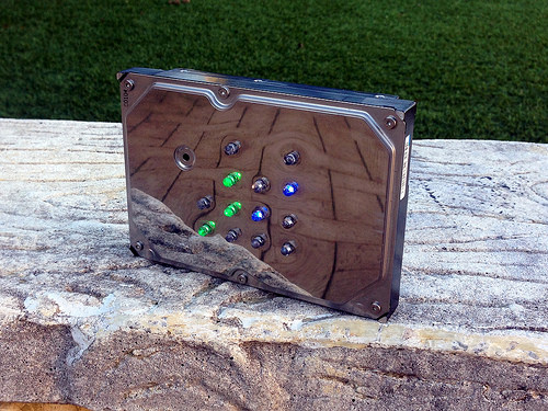
[Aaron] got creative for his clock enclosure, upcycling an old hard drive. All of the hard drive guts were removed and replaced with his own electronics. The front cover had 13 holes drilled out for the LED’s. There are six green LED’s to display the hour, and seven blue LED’s for the minute. The LED’s were wired up as common cathode. Since the hard drive cover is conductive, [Aaron] covered both sides of his circuit board with electrical tape and hot glue to prevent any short circuits. The end result is an elegant binary clock that any geek would be proud of.


Filed under: Arduino Hacks

Kit Review – Maniacal Labs Epoch Clock

Introduction

The subject of our latest kit review is the “Epoch Clock” from Maniacal Labs, a new organisation started by three young lads with some interesting ideas. Regular readers will know we love a clock – so when the opportunity came to review this one, we couldn’t say no.

At this point you may be thinking “what is Epoch time anyway?”. Good question! It is the number of seconds elapsed since the first of January, 1970 (UTC) – and used by Unix-based computers as the start of their time universe. (For more on the theory of Epoch time, check out Wikipedia). For example – 1379226077 Epoch time is Sun, 15 Sep 2013 06:21:17 GMT. That’s a lot of seconds. If you’re curious, you can do more calculations with the EpochTime website.

Moving forward, this clock kit will show Epoch time in full 32-bit binary glory, using a DS1307 real-time clock IC (with backup battery) and is controlled with an ATmega328P-PU – so you can modify the code easily with the Arduino IDE or WinAVR (etc).

Assembly

The creators have spent a lot of time on not only the packaging and out-of-box-experience, but also the documentation and setup guide – so as long as you’re fine with simple through-hole soldering the kit will not present any challenges. The kit arrives in a sturdy box:

… with well packaged components. Everything is included for the finished product, as well as IC sockets, the RTC backup battery and a USB cable so you can power the clock from a USB hub:

The PCB is a good thickness, and has a clear silk-screen and solder mask:

Construction is simple, just follow the step-by-step instructions. Starting with the USB socket for power:

… then the resistors:

… the LEDs:

… all 32 of them. Note that the LEDs don’t sit flush with the PCB, so a little effort is required to keep them aligned:

 Then the rest of the components just fit as expected. I’ve also added the included header pins for an FTDI programming cable and ICSP to keep my options open:

Then simply fit the battery, insert the ICs and you’re done:

Using the clock

The microcontroller is pre-programmed, so you can use the clock straight away. You will however need to set the time first. To make this incredibly easy, there is a special web page that displays the current time and Epoch time, which steps you through the process of setting the time using the buttons.

Or with some code available on the kit github page and a programming cable, you can automatically sync it to the clock. Once setup, the battery will keep the current time in the RTC nicely. The clock is powered by 5V, which is easily supplied with the included USB cable, or you can always hack in your own feed.

So what does Epoch time in 32-bit binary look like? Here’s a short video of the clock in action:

Reading the time requires converting the binary number displayed with the LEDs back to a decimal number – which is of course the Epoch count of seconds since 1/1/1970. Math teachers will love this thing.

But wait, there’s more!

If you get tired of the blinking, there’s a test function which is enabled by holding down both buttons for a second, which turns the Epoch Clock into a nifty Larson Scanner:

To create your own sketches or examine the design files in more detail, it’s all on the clock github page. From a hardware perspective you have an ATmega328P-PU development board with a DS1307 battery-backed real-time clock – with 32 LEDs. So you could also create your own kind of clock or other multi-LED blinking project without too much effort. Review the EpochClockSchematic (.pdf) to examine this in more detail.

Conclusion

I really enjoyed this kit – it was easy to assemble, I learned something new and frankly the blinking LEDs can be quite soothing. The clock would make a great for a conversation-starter in the office, or would make an ideal gift for any Sheldon Cooper-types you might be associated with. Or have competitions to see who can convert the display to normal time. After shots.

Nevertheless it’s a fun and imaginative piece of kit, fully Open Hardware-compliant – and if you’ve made it this far – get some and have fun. Full-sized images are on flickr. Interested in Arduino? Check out my new book “Arduino Workshop” from No Starch Press.

In the meanwhile have fun and keep checking into tronixstuff.com. Why not follow things on twitterGoogle+, subscribe  for email updates or RSS using the links on the right-hand column? And join our friendly Google Group – dedicated to the projects and related items on this website. Sign up – it’s free, helpful to each other –  and we can all learn something.

[Note – The kit reviewed was a promotional consideration from Maniacal Labs]

The post Kit Review – Maniacal Labs Epoch Clock appeared first on tronixstuff.

Tronixstuff 15 Sep 10:29

Various 1 Hz Oscillator Methods

Introduction

During the fun and enjoyment of experimenting with electronics there will come a time when you need a nice 1 Hz oscillator to generate a square-wave signal to drive something in the circuit. On… off… on… off… for all sorts of things. Perhaps a metronome, to drive a TTL clock, blink some LEDs, or for more nefarious purposes. No matter what you need that magic 1 Hz for – there’s a variety of methods to generate it – some more expensive than others – and some more accurate than others.

A few of you may be thinking “pull out the Arduino” and yes, you could knock out a reasonable 1 Hz – however that’s fine for the bench, but wild overkill for embedding a project as a single purpose. So in this article we’ll run through three oscillator methods that can generate a 1 Hz signal (and other frequencies) using methods that vary in cost, accuracy and difficulty – and don’t rely on mains AC. That will be a topic for another day.

Using a 555 timer IC

You can solve this problem quite well for under a dollar with the 555, however the accuracy is going to heavily rely on having the correct values for the passive components. We’ll use the 555 in astable mode, and from a previous article here’s the circuit:

 And with a 5V power supply, here’s the result:

As you can see the cycle time isn’t the best, which can be attributed to the tolerance of the resistors and capacitor C1. A method to increase the accuracy would be to add small trimpots in series with the resistors (and reduce their value accordingly by the trimpot value) – then measure the output with a frequency counter (etc). whilst adjusting the trimpots. If you’re curious about not using C2, the result of doing so introduces some noise on the rising edge, for example:

So if you’ve no other option, or have the right values for the passives – the 555 can do the job. Or get yourself a 555 and experiment with it, there’s lots of fun to be had with it.

Using a GPS receiver module

A variety of GPS modules have a one pulse per second output (PPS) and this includes my well-worn EM406A module (as used in the Arduino tutorials):

With a little work you can turn that PPS output into a usable and incredibly accurate source of 1 Hz. As long as your GPS can receive a signal. In fact, this has been demonstrated in the April 2013 edition of Silicon Chip magazine, in their frequency counter timebase project. But I digress.

If you have an EM406A you most likely have the cable and if not, get one to save your sanity as the connector is quite non-standard. If you’re experimenting a breakout board will also be quite convenient, however you can make your own by just chopping off one end of the cable and soldering the required pins – for example:

You will need access to pins 6, 5, 2 and 1. Looking at the socket on the GPS module, they are numbered 6 to 1 from left to right. Pin 6 is the PPS output, 5 is GND, 2 is for 5V and 1 is GND. Both the GNDs need to be connected together.

Before moving forward you’re probably curious about the pulse, and want to see it. Good idea! However the PPS signal is incredibly quick and has an amplitude of about 2.85 V. If you put a DSO on the PPS and GND output, you can see the pulses as shown below:

 To find the length of the pulse, we had to really zoom in to a 2 uS timebase:

 Wow, that’s small. So a little external circuitry is required to convert that minuscule pulse into something more useful and friendly. We’ll increase the pulse length by using a “pulse stretcher”. To do this we make a monostable timer (“one shot”) with a 555. For around a half-second pulse we’ll use 47k0 for R1 and 10uF for C1. However this triggers on a low signal, so we first pass the PPS signal through a 74HC14 Schmitt inverter – a handy part which turns irregular signals into more sharply defined ones – and also inverts it which can then be used to trigger the monostable. Our circuit:

 and here’s the result – the PPS signal is shown with the matching “stretched” signal on the DSO:

So if you’re a stickley for accuracy, or just want something different for portable or battery-powered applications, using the GPS is a relatively simple solution.

Using a Maxim DS1307/DS3232 real-time clock IC

Those of you with a microcontroller bent may have a Maxim DS1307 or DS3232. Apart from being pretty easy to use as a real-time clock, both of them have a programmable square wave output. Connection via your MCU’s I2C bus is quite easy, for example with the DS1307:

Using a DS3232 is equally as simple. We use a pre-built module with a similar schematic. Once you have either of them connected, the code is quite simple. For the DS1307 (bus address 0x68), write 0x07 then 0x11 to the I2C bus – or for the DS3232 (bus address is also 0x68) write 0x0E then 0x00. Finally, let’s see the 1 Hz on the DSO:

Certainly not the cheapest method, however it gives you an excellent level of accuracy without the GPS.

Conclusion

By no means is this list exhaustive, however hopefully it was interesting and useful. If there’s any other methods you’d like to see demonstrated, leave a comment below and we’ll see what’s possible. And if you made it this far – check out my new book “Arduino Workshop” from No Starch Press.

In the meanwhile have fun and keep checking into tronixstuff.com. Why not follow things on twitterGoogle+, subscribe  for email updates or RSS using the links on the right-hand column? And join our friendly Google Group – dedicated to the projects and related items on this website. Sign up – it’s free, helpful to each other –  and we can all learn something.

The post Various 1 Hz Oscillator Methods appeared first on tronixstuff.

Tronixstuff 31 Jul 14:07
1 hz  555  74hc14  astable  clock  clocks  digital  ds1307  ds3232  em406a  gps  logic  pps  timebase  tronixstuff  ttl  tutorial