Introduction
Over the last year there have been a few crowd-funded projects that offered very inexpensive Arduino-compatible boards. Frankly most of them weren’t anything out of the ordinary, however one of them is quite interesting due to the particular design of the board, and is the subject of this review.
An established company Iteadstudio ran a successful Indiegogo campaign last December to fund their “Iteaduino Lite – Most inexpensive full-sized Arduino derivative board”. Having a spare US$5 we placed an order and patiently waited for the board. Being such a low price it was guaranteed to raise the funding – but was it worth the money? Or the effort? Possibly.
The board
In typical fashion the board arrived in bare packaging:

The Iteaduino Lite isn’t that surprising at first glance:

To the new observer, it looks like an Arduino board of some sort. Nice to see all those GPIO pins with double breakouts. No surprises underneath:

The URL on the bottom is incorrect, instead visit http://imall.iteadstudio.com/iteaduino-lite.html. Looking at the board in more detail, there are some interesting points of difference with the usual Arduino Uno and compatibles.
The USB interface is handled with the Silabs CP2102 USB to UART bridge IC:

The next difference is the power circuitry – instead of using a linear voltage regulator, Itead have used a contemporary DC-DC converter circuit which can accept between 7 and 24V DC:

Furthermore, the entire board can operate at either 5V or 3.3V, which is selected with the slide switch in the above image. Finally – the microcontroller. Instead of an Atmel product, Itead have chosen the LogicGreen LGT8F88 microcontroller, a domestic Chinese product:

And there are only two LEDs on the Iteaduino Lite, for power and D13. The LED on D13 ins’t controlled via a MOSFET like other Arduino-compatibles, instead it’s simply connected to GND via a 1kΩ resistor.
Getting started with the Iteaduino Lite
The stacking header sockets will need to be soldered in – the easiest way is to insert them into the board, use an shield to hold them in and flip the lot upside down:

Which should give you neatly-installed headers:

Watch out for the corners of the board, they’re quite sharp. Next, you need to install the USB driver for the CP2102. My Windows 7 machine picked it up without any issues, however the drivers can be downloaded if necessary.
Finally a new board profile is required for the Arduino IDE. At the time of writing you’ll need Arduino IDE v1.0.5 r2. Download this zip file, and extract the contents into your ..\Arduino-1.0.5-r2\hardware folder. The option should now be available in the Tools > Board menu in the IDE, for example:

From this point you can run the blink example to check all is well. At this point you will realise one of the limitations of the Iteaduino Lite – memory. For example:

You only have 7168 bytes of memory for your sketches – compared to 32, 256 for an Arduino Uno or compatible. The reason for this is the small capacity of …
The LogicGreen LGT8F88 microcontroller
This MCU is a Chinese company’s answer to the Atmel ATmega88A. You can find more details here, and Itead also sells them separately. The LGT8F88 offers us 8Kbyte of flash memory of which 0.7KB is used by bootloader, 1 KB of SRAM and 504 bytes (count ’em) of EEPROM. Apparently it can run at speeds of up to 32 MHz, however the LGT8F88 is set to 16 MHz for the Iteaduino Lite.
According to Logic Green, their LGT8F88 “introduce a smart instruction cache, which can fetch more instructions one time, effectively decrease memory accessing operations“. So to see if there’s a speed bump, we uploaded the following sketch – written by Steve Curd from the Arduino forum. It calculates Newton Approximation for pi using an infinite series:
//
// Pi_2
//
// Steve Curd
// December 2012
//
// This program approximates pi utilizing the Newton's approximation.  It quickly
// converges on the first 5-6 digits of precision, but converges verrrry slowly
// after that.  For example, it takes over a million iterations to get to 7-8
// significant digits.
//
// I wrote this to evaluate the performance difference between the 8-bit Arduino Mega,
// and the 32-bit Arduino Due.
//

#define ITERATIONS 100000L    // number of iterations
#define FLASH 1000            // blink LED every 1000 iterations

void setup() {
  pinMode(13, OUTPUT);        // set the LED up to blink every 1000 iterations
  Serial.begin(57600);
}

void loop() {

  unsigned long start, time;
  unsigned long niter=ITERATIONS;
  int LEDcounter = 0;
  boolean alternate = false;
  unsigned long i, count=0;
  float x = 1.0;
  float temp, pi=1.0;

  Serial.print("Beginning ");
  Serial.print(niter);
  Serial.println(" iterations ...");
  Serial.println();

  start = millis();
  for ( i = 2; i < niter; i++) {
    x *= -1.0;
    pi += x / (2.0f*(float)i-1.0f);
    if (LEDcounter++ > FLASH) {
      LEDcounter = 0;
      if (alternate) {
        digitalWrite(13, HIGH);
        alternate = false;
      }
      else {
        digitalWrite(13, LOW);
        alternate = true;
      }
      temp = 40000000.0 * pi;
    }
  }
  time = millis() - start;

  pi = pi * 4.0;

  Serial.print("# of trials = ");
  Serial.println(niter);
  Serial.print("Estimate of pi = ");
  Serial.println(pi, 10);

  Serial.print("Time: ");
  Serial.print(time);
  Serial.println(" ms");

  delay(10000);
}
For a baseline comparison, an Arduno Uno R3 completes the calculations in 5563 ms:

… and the Iteaduino Lite completed it in 5052 ms:

So that’s around a 10% speed increase. Not bad at all. The LGT8F88 also has the requisite GPIO, SPI, and I2C available as per normal Arduino Uno boards. You can download the data sheet with more technical details from here. Frankly the LGT8F88 is an interesting contender in the marketplace, and if Logic Green can offer a DIP version at a good price, the ATtiny fans will have a field day. Time will tell.
Power Circuit
The DC-DC circuit promises 5V output, with up to 24V DC input – so we cranked the input to 24V, put a 1A load on the 5V output – and put the DSO over 5V to measure the variations – with a neat result:

So no surprises there at all, the Iteaduino Lite gives you more flexible power supply options than the usual Arduino board. However an eagle-eyed reader notes that a few of the capacitors are only rated at 25V – especially the two right after the DC socket/Vin. You can see this in the schematic (.pdf). So take that into account, or drop your Vin to something more regular such as below 12V.
Conclusion
The Iteaduino Lite is an interesting experiment in bargain Arduino-compatible boards. However we say “why bother?” and just get a Uno R3-compatible board.
At the end of the day – why bother with this board? For a little extra you can get boards with the ATmega328P or 32U4 which gives you 100% compatibility. Nevertheless, this was an interesting experiment. Full-sized images are available on flickr. And if you enjoyed this article, or want to introduce someone else to the interesting world of Arduino – check out my book (now in a third printing!) “Arduino Workshop”.

Have fun and keep checking into
tronixstuff.com. Why not follow things on
twitter,
Google+, subscribe for email updates or RSS using the links on the right-hand column, or join our
forum – dedicated to the projects and related items on this website.
Sign up – it’s free, helpful to each other – and we can all learn something.
The post Review – Iteaduino Lite “nearly 100% Arduino-compatible” board appeared first on tronixstuff.


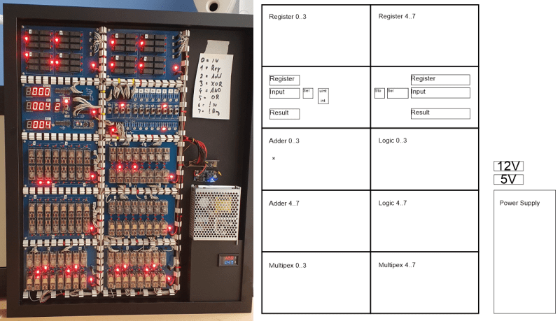
 operating on 4-bits. To handle a byte-length word, boards are simply cascaded, making a total of eight. The register, adder, logic function, and multiplex boards are the heart of the build with an additional two custom boards for visualization (using an Arduino for convenience) and IO forming the interface. After all, a basic CPU is just an ALU and some control around it, the magic is really in the ALU.
 but that’s the job of a separate board. The adder function is the most basic, simply a pair of half-adders and an OR-gate to handle the chaining of the carry inputs and generate the carry chain output.
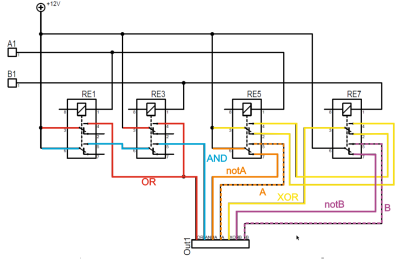


