Posts with «home automation» label

Trigger Your Home Automation Routines With Home Buttons

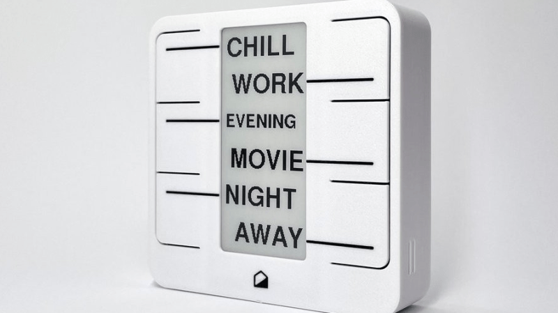
Home automation systems are all well and good, so long as the person who built it all is around to drive it. Let’s face it, they’re quite often a complex web of interconnected systems, all tied to the specifics of one’s home — and someone less familiar with it all could get a little irritated if, on a chilly day, the interface to the boiler is via a Python script, and something won’t work. Just saying. Home Buttons by [Matej Planinšek] over on Hackaday.IO is a nicely polished project, which aims to take some of the hackiness out of such automation by providing a sleek front end to those automation routines, enabling anyone to rock on over and set one in action without hassle.

The PCB is based around the ESP32-S2-mini which deals with WiFi connectivity and integration with Home Assistant using the usual MQTT protocol. We expect integration with other flavors of home automation would not be difficult to achieve. The center of the unit holds a simple E-Ink display, for that low-standby power. Specifically, the unit chosen is a Good Display GDEY029T94 2.9″ which this scribe can confirm is easy to interface and pretty cheap to purchase from the usual Chinese online vendors. This was matched up with six clicky Alps SKRB-series low-profile tact switches, which sit on either side of the display, and corresponds to a flexure-type affair on the 3D printed front casing. Neat and simple.

The PCB design was provided in Altium format, which you can find on the project GitHub page. This shows a straightforward design, with a few nice little details here and there. The internally mounted 186550 cell is reportedly good for at least a year of operation, but when time, it can be charged via USB. A Xysemi XB8608AF (PDF) protection chip provides appropriate limiting for the 186550 cell, shielding it from the perils of overcharging, discharging, and whatnot. Not that that is likely in this current setup. A Sensiron SHTC3 humidity and temperature sensor is also in there, hanging off the I2C bus, which makes sense for this application.

Home Automation hacks are plenty on these pages, like this scroll-wheel interface, for instance. If all this stuff is looking quite overbearingly complicated to get into, how about starting with a Pico W?

Home Automation for Fans of Quick-and-Dirty Solutions

At Hackaday, we celebrate all kinds of projects, but we’ll have to admit that the polished and professional-looking builds tend to catch our eye a lot more than perhaps they should. There’s plenty of love to be had for the rougher builds, though, of which this quick-and-dirty home automation system is a perfect example.

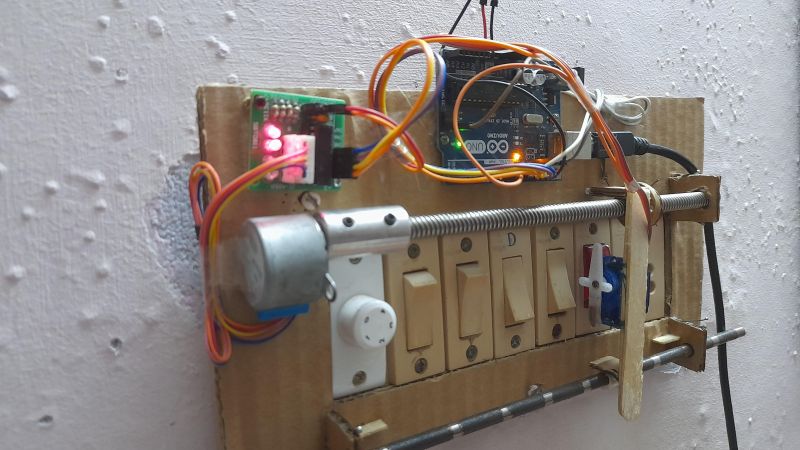
Before anyone rushes to state the obvious with, “Should have used some relays,” consider that [MAKE_IT_WITH_ME]’s stated goal was to get the basics of a home automation system built with pretty much nothing but what can be found in one of those Arduino starter kits. And further, consider that landlords might not look kindly on tenants who wire a bunch of SSRs or Sonoff switches into the walls of their building. So this minimalist build is perfect for certain use cases. Its interface to the building’s electrical system is 100% mechanical, via a servo that travels along the bank of switches on a stepper-driven leadscrew. The servo has a modified horn to properly flick the rocker-style switches, and although changing from switch to switch is a bit slow, it works surprisingly well. The video below shows it in action.

While we can see it possibly working as-is for Decora-style switches that are seen in some markets, we’d think some mods would be in order for the more standard toggle-style switch — perhaps a finger extending out from the horn, along with a second servo to tilt the whole assembly away from the wall to allow it to clear the switch bats.


Electric Window Mechanism Into A Electric Screen Door

In many parts of the world leaving open a door or window is a good way to get a house full of bugs. Remembering to close doors behind them can be surprisingly hard for members of the human race, so the [DuctTape Mechanic] used the components from a car’s electric window to automate his sliding screen door.

After the excess pieces were cut of the rail, the motor and rail were mounted on top of the door frame. A long bolt is attached to the moving plate on the rail, which pushes on the pack of the door to close it. After closing, the mechanism returns to its open position, allowing the door to be opened by hand. The motor is controlled by an Arduino running a very simple sketch, which senses if the door is closed with a microswitch and starts a 10 second countdown once opened. Two relays are used to create an H-bridge circuit to drive the motor in both directions.

It doesn’t look like there is any provision to detect if it is obstructed. A simple solution could be to make the push rod spring-loaded, so it can slide over the door if there is excessive resistance. This project is successful as a proof of concept, but making the wiring neater and covering everything would be a welcome upgrade.

If you only want to let certain creatures into your house, we have no shortage of automated pet door for your hacking pleasure.

Zero-Intrusion Wireless Light Switch

What do you do if your light switch is too far from your desk, and you’re in a rental property so you can’t put in extra wiring to install an electronic control for it? Get up and turn it on or off by hand? Of course not!

If you are [Guyfromhe], you solve this problem with a servo attached to a screw-on light switch faceplate, and you control it with a pair of Arduino/nRF24L01 combos. It’s a pretty simple arrangement, the wireless link simply takes the place of a serial cable that instructs the Arduino on the light switch to operate the servo that in turn moves the switch. The whole thing is triggered through his home automation system, which in turn responds to an Amazon Dash button on his desk. Yes, it’s complex. But turning on the light has been automated without intrusion into his landlord’s domain, and that’s all that matters.

On a more serious note, he’s put some Arduino code up on his write-up, as well as a YouTube video we’ve put below the break.

This is by no means the first such switch we’ve seen, after all we featured a nicer 3D printed servo light switch the other month, and one with a breadboarded Arduino in 2015. While we’re at it though, it would be nice to see a few designed for European switches too.


Filed under: home hacks

Garage Door Monitor with Cayenne


Description

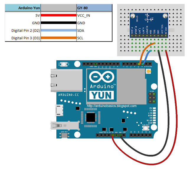
Using the HMC5883L magnetometer sensor of the GY-80 module from ICStation to monitor a garage door and notify when it has been opened or closed. The Cayenne service provides much of the monitoring and notifying functionality. A major feature of this project. Cayenne takes care of all of the complicated work behind the scenes, making it easy to connect your Arduino to the cloud and allow you to monitor your garage from virtually anywhere.
 
This project was created specifically to monitor a garage, but you will soon discover that this project could be used to monitor a whole host of other things. Monitor your front door, your back door, your bag, your chair, your cookie jar.
 
Monitor for peace of mind, or catch someone in the act of stealing your stuff. This project has got you covered. Let's see how:


HMC5883L DataSheet:

You can find the datasheet for the HMC5883L pretty easily by searching on the internet.
HMC5883L datasheet - Sparkfun


Arduino Libraries and IDE

Here is a link to the Arduino IDE download. The IDE is required to upload code to the Seeeduino Cloud.

You need the Cayenne Library installed in your Arduino IDE.
You can find the Cayenne library here:
Cayenne Libarary
 
There are libraries on the internet for the GY-80 module, however, it is relatively easy to use the magnetometer on this module. And therefore no libraries are required for the sensor. If you would like some more information about using the magnetometer sensor, and how to get the most out of it, then please have a look at my previous tutorial which goes into much more detail.


ARDUINO CODE:


You need to make sure to insert your OWN Cayenne token into the sketch above. You will get this token when connecting your Arduino to the Cayenne service. Watch the video for further explanation.


Fritzing diagram

Cayenne Widgets

Please make sure to watch the video to see how to connect the Seeeduino Cloud to Cayenne and how to create the Cayenne widgets. Cayenne widgets are necessary to create the dashboard on your phone or browser. They will also interact with the Arduino sketch, and will also be involved in creating the notification system. The following links will take you to the relevant part of the video:

The Master switch button is used to switch monitoring from OFF to ON (and vice versa). Therefore you can choose when to monitor the garage and when to stop monitoring. When first installing the project onto your garage door, and turning the Seeeduino Cloud on, it will automatically calibrate each sensor to a value of 1000.
 
If you experience any drift away from 1000 for whatever reason, simply press the Request calibration button, and each sensor will be recalibrated back to 1000. The x,y and z axis widgets are there so that you can see the readings coming from the magnetometer sensor. And when any of the axis variables breach the threshold away from 1000, it will trigger the Door Status widget. This is how we can tell if the door is open or closed.
 
We also use the Door Status widget to help with the notification system. When the Door status changes from "Closed" to "Open", a notification trigger will be activated, and a message will be sent via email or SMS. This notification is useful for monitoring when the door was opened. If you happen to recalibrate when the door is open. You will get a notification when the garage door closes.


Concluding comments

This project is relatively simple, and quite easy to set up. What I liked about this project was the versatility and alternate uses. You can use the same setup to monitor many different things. It is not just limited to monitoring a garage door. But being able to tell whether my garage door is opened or closed, especially after I have driven away from my house , is really cool. Now I don't have to drive all the way back home to check. Let me know if you have replicated this project, and also what kinds of things you decided to monitor with this project.

Banish Dangerous Shadows Under Kitchen Cabinets

[nebulous] has a lot of problems with his kitchen cabinets. Aside from a noted lack of micro-controllers, he was especially suspicious of the dark spaces under them. Anything could be hiding there.

The core of the project is a $10 Arduino-compatible esp8266 board from digistump. The board is powered by the five volt regulator of an L298N motor driver module hooked to a power-supply. All this controls a set-of LED strips adhered to the underside of the cabinets with the traditionally bad adhesive strips with which they come standard. We can predict an hour spent bent awkwardly cursing at them, a hot-glue gun in one hand, in [nebulous]’s future. The whole set-up is housed in a SparkFun cardboard box above the microwave. You can barely tell it’s not a commercial product.

We’re not certain if we like a future where even our cabinetry has an IP address. However, this is a good weekend project that could make all our cabinetry brighter, safer, and more connected.


Filed under: home hacks, led hacks

Ridiculously Automated Dorm Room

Take three NRF24L0+ radios, two Arduino Nanos, and a Raspberry Pi. Add a bored student and a dorm room at Rice University. What you get is the RRAD: Rice Ridiculously Automated Dorm. [Jordan Poles] built a modular system inspired by BRAD (the Berkeley Ridiculously Automated Dorm).

RRAD has three types of nodes:

  • Actuation nodes – Allows external actuators like relays or solenoids
  • Sensory nodes – Reports data from sensors (light, temperature, motion)
  • Hub nodes – Hosts control panel, records data, provides external data interfaces

The hub also allows [Jordan] to control things with his Android phone with Tasker. He has the Arduino and Raspberry Pi code on GitHub if you want to ridiculously automate something of your own. You’d probably want to adapt it to your dorm room, house, or RV, though.

[Jordan] continues to work on the project and promises to have voice recognition and other features, soon. We cover a lot of home automation projects including some others described as ridiculous. The video below shows BRAD, the inspiration for RRAD.


Filed under: Android Hacks, Arduino Hacks, home hacks, Raspberry Pi

Roomba, I Command Thee: Use Raspberry Pi for Voice Control

Take advantage of these open source resources to set up voice control with Raspberry Pi and bark orders at your home appliances.

Read more on MAKE

The post Roomba, I Command Thee: Use Raspberry Pi for Voice Control appeared first on Make: DIY Projects, How-Tos, Electronics, Crafts and Ideas for Makers.

MT8870 DTMF - Dual Tone Multi Frequency Decoder

Project Description

We will be using an MT8870 DTMF module with an Arduino UNO to control a small servo motor in this project. The DTMF module gives the Arduino super-powers and allows you to control the Servo motor in so many ways. For example, this tutorial will show you how to control the servo motor using:
  • a YouTube Video
  • a voice recorder
  • A web application (Online tone generator)
  • A smart phone app (DTMF Pad)
  • A touch-tone phone to cell-phone call
All of these control methods will take advantage of the same exact Arduino code/sketch. But how???
The MT8870 DTMF decoder is quite a neat little module that allows you incorporate DTMF technology into your arduino projects. DTMF stands for Dual-Tone Multi-Frequency. DTMF tones are commonly associated with touch-tone phones and other telecommunication systems. When you press the number "1" on a touch-tone phone, two sine waves with frequencies: 697Hz and 1209Hz are combined to produce a unique DTMF signal which can be transmitted through the phone line. The MT8870 DTMF module can take this signal as an input, and decode it to produce a binary output.


The DTMF module does not care how you produce the DTMF tone. However, if it receives this tone, it will decode it. We can take advantage of this feature to supply the module with tones from different sources. The module has a 3.5mm port for line input. Providing you can connect your DTMF source to this line input in some way, it should work. I must warn you, however that this is a line input and NOT a microphone input. If you wanted to use a microphone, you will need to boost or amplify the signal before sending it to the DTMF module.
 
You will need the following parts for this project
 

Parts Required:

Software/Apps Required

Arduino Sketch


Upload the following sketch to the Arduino.
 

1
2
3
4
5
6
7
8
9
10
11
12
13
14
15
16
17
18
19
20
21
22
23
24
25
26
27
28
29
30
31
32
33
34
35
36
37
38
39
40
41
42
43
44
45
46
47
48
49
50
51
52
53
54
55
56
57
58
59
60
61
62
/* ================================================================================================================================================== Project: MT8870 DTMF Servo sketch Author: Scott C Created: 4th August 2015 Arduino IDE: 1.6.4 Website: http://arduinobasics.blogspot.com/p/arduino-basics-projects-page.html Description: This project will allow you to control a Servo motor using an Arduino UNO and a MT8870 DTMF Module. The DTMF signal is received through the 3.5mm port of the DTMF module and is decoded. We will use the decoded output to control the position of the Servo. A SG-5010 Servo motor was used in this project. ===================================================================================================================================================== *///This sketch uses the Servo library that comes with the Arduino IDE #include <Servo.h> //Global variables----------------------------------------------------------------------------------------- Servo SG5010; // The SG5010 variable provides Servo functionality int servoPosition = 0; // The servoPosition variable will be used to set the position of the servo byte DTMFread; // The DTMFread variable will be used to interpret the output of the DTMF module. const int STQ = 3; // Attach DTMF Module STQ Pin to Arduino Digital Pin 3 const int Q4 = 4; // Attach DTMF Module Q4 Pin to Arduino Digital Pin 4 const int Q3 = 5; // Attach DTMF Module Q3 Pin to Arduino Digital Pin 5 const int Q2 = 6; // Attach DTMF Module Q2 Pin to Arduino Digital Pin 6 const int Q1 = 7; // Attach DTMF Module Q1 Pin to Arduino Digital Pin 7 /*========================================================================================================= setup() : will setup the Servo, and prepare the Arduino to receive the MT8700 DTMF module's output. ========================================================================================================== */void setup() { SG5010.attach(9); // The Servo signal cable will be attached to Arduino Digital Pin 9 SG5010.write(servoPosition); // Set the servo position to zero. //Setup the INPUT pins on the Arduino pinMode(STQ, INPUT); pinMode(Q4, INPUT); pinMode(Q3, INPUT); pinMode(Q2, INPUT); pinMode(Q1, INPUT);} /*========================================================================================================= loop() : Arduino will interpret the DTMF module output and position the Servo accordingly ========================================================================================================== */void loop() { if(digitalRead(STQ)==HIGH){ //When a DTMF tone is detected, STQ will read HIGH for the duration of the tone. DTMFread=0; if(digitalRead(Q1)==HIGH){ //If Q1 reads HIGH, then add 1 to the DTMFread variable DTMFread=DTMFread+1; } if(digitalRead(Q2)==HIGH){ //If Q2 reads HIGH, then add 2 to the DTMFread variable DTMFread=DTMFread+2; } if(digitalRead(Q3)==HIGH){ //If Q3 reads HIGH, then add 4 to the DTMFread variable DTMFread=DTMFread+4; } if(digitalRead(Q4)==HIGH){ //If Q4 reads HIGH, then add 8 to the DTMFread variable DTMFread=DTMFread+8; } servoPosition = DTMFread * 8.5; //Set the servoPosition varaible to the combined total of all the Q1 to Q4 readings. Multiply by 8.5 to amplify the servo rotation. } SG5010.write(servoPosition); //Set the servo's position according to the "servoPosition" variable. }


Fritzing Sketch


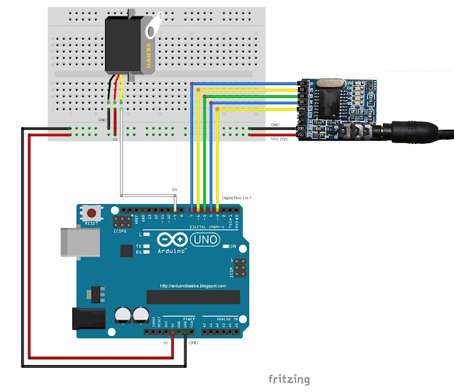
Connect the Arduino to the MT8870 DTMF module, and to a Servo.
Use the following Fritzing sketch as a guide.
 
(Click the image above to enlarge it)


Discussion


You will need to connect a cable from the DTMF module's 3.5mm port to that of your smart phone, computer, voice recorder or any other DTMF source of your choice.
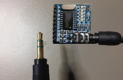


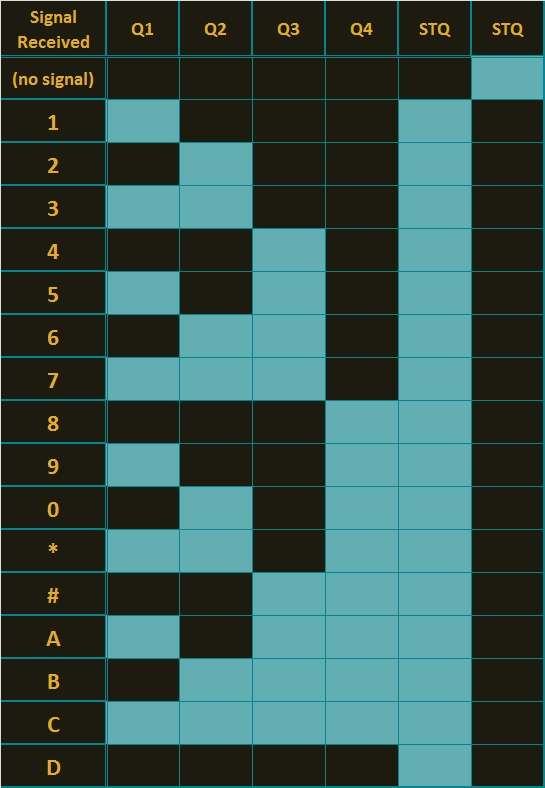
When you power up your Arduino, the Servo motor should turn all the way to the left to it's zero position. Once the DTMF module receives a DTMF signal, it will identify the relevant frequecies as described in the table at the beginning of this tutorial, and produce a binary like output. You will notice the DTMF module's onboard LEDs light up when a tone is detected. Onboard LED (D5) will turn on for the length of the DTMF tone it just received, and turn off when the tone has stopped. On the other hand, the onboard LEDs (D1 to D4) will light up depending on the tone received, and will remain lit until the module receives another tone. The onboard LEDs are a visual representation of the voltages applied to the DTMF module's pins (Q1 to Q4, and STQ). Q1 matches D1, Q2 matches D2 etc etc. and STQ matches D5.
 
You will notice that there are two STQ pins on the DTMF module. The STQ pin that is closest to Q4 will only go high when a DTMF tone is detected, and will remain high for the duration of the tone. The other STQ pin is the exact opposite. It will switch LOW when a tone is received and remain LOW for the duration of the tone. When there is no tone, this STQ pin will remain HIGH. The table below provides a summary of the DTMF module outputs, with a blue box representing a voltage applied to that pin (HIGH), whereas a black box indicates no voltage applied (LOW).

 
In order to follow this project, you need a source of DTMF tones. You can produce DTMF tones using a touch-tone phone, or through the use of a DTMF Pad app. If you are feeling creative, you can create a DTMF song/tune like the one I posted on YouTube. You can see the video below:


As you can see from the video, I also recorded the DTMF tune onto a voice recorder, and was able to control the servo that way. If you are not feeling creative, you can visit this website to create DTMF tones from your browser.

Concluding comments


This project was very fun, and shows some novel ways to control your Arduino. After completing the project, I realised that I could use this module to alert me when new emails or messages arrive on my phone or computer. If you have the ability to change the email or message notification sound to a DTMF tone, you should be able to get the module and Arduino to respond accordingly. Oh well, maybe I'll save that project for another day.
 
If this project helped you in anyway or if you use my code within your project, please let me know in the comments below. I would be interested to see what you did.


If you like this page, please do me a favour and show your appreciation :

 
Visit my ArduinoBasics Google + page.
Follow me on Twitter by looking for ScottC @ArduinoBasics.
I can also be found on Pinterest and Instagram.
Have a look at my videos on my YouTube channel.


However, if you do not have a google profile...
Feel free to share this page with your friends in any way you see fit.