Posts with «home automation» label

MT8870 DTMF - Dual Tone Multi Frequency Decoder

Project Description

We will be using an MT8870 DTMF module with an Arduino UNO to control a small servo motor in this project. The DTMF module gives the Arduino super-powers and allows you to control the Servo motor in so many ways. For example, this tutorial will show you how to control the servo motor using:
  • a YouTube Video
  • a voice recorder
  • A web application (Online tone generator)
  • A smart phone app (DTMF Pad)
  • A touch-tone phone to cell-phone call
All of these control methods will take advantage of the same exact Arduino code/sketch. But how???
The MT8870 DTMF decoder is quite a neat little module that allows you incorporate DTMF technology into your arduino projects. DTMF stands for Dual-Tone Multi-Frequency. DTMF tones are commonly associated with touch-tone phones and other telecommunication systems. When you press the number "1" on a touch-tone phone, two sine waves with frequencies: 697Hz and 1209Hz are combined to produce a unique DTMF signal which can be transmitted through the phone line. The MT8870 DTMF module can take this signal as an input, and decode it to produce a binary output.


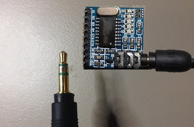
The DTMF module does not care how you produce the DTMF tone. However, if it receives this tone, it will decode it. We can take advantage of this feature to supply the module with tones from different sources. The module has a 3.5mm port for line input. Providing you can connect your DTMF source to this line input in some way, it should work. I must warn you, however that this is a line input and NOT a microphone input. If you wanted to use a microphone, you will need to boost or amplify the signal before sending it to the DTMF module.
 
You will need the following parts for this project
 

Parts Required:

Software/Apps Required

Arduino Sketch


Upload the following sketch to the Arduino.
 

1
2
3
4
5
6
7
8
9
10
11
12
13
14
15
16
17
18
19
20
21
22
23
24
25
26
27
28
29
30
31
32
33
34
35
36
37
38
39
40
41
42
43
44
45
46
47
48
49
50
51
52
53
54
55
56
57
58
59
60
61
62
/* ================================================================================================================================================== Project: MT8870 DTMF Servo sketch Author: Scott C Created: 4th August 2015 Arduino IDE: 1.6.4 Website: http://arduinobasics.blogspot.com/p/arduino-basics-projects-page.html Description: This project will allow you to control a Servo motor using an Arduino UNO and a MT8870 DTMF Module. The DTMF signal is received through the 3.5mm port of the DTMF module and is decoded. We will use the decoded output to control the position of the Servo. A SG-5010 Servo motor was used in this project. ===================================================================================================================================================== *///This sketch uses the Servo library that comes with the Arduino IDE #include <Servo.h> //Global variables----------------------------------------------------------------------------------------- Servo SG5010; // The SG5010 variable provides Servo functionality int servoPosition = 0; // The servoPosition variable will be used to set the position of the servo byte DTMFread; // The DTMFread variable will be used to interpret the output of the DTMF module. const int STQ = 3; // Attach DTMF Module STQ Pin to Arduino Digital Pin 3 const int Q4 = 4; // Attach DTMF Module Q4 Pin to Arduino Digital Pin 4 const int Q3 = 5; // Attach DTMF Module Q3 Pin to Arduino Digital Pin 5 const int Q2 = 6; // Attach DTMF Module Q2 Pin to Arduino Digital Pin 6 const int Q1 = 7; // Attach DTMF Module Q1 Pin to Arduino Digital Pin 7 /*========================================================================================================= setup() : will setup the Servo, and prepare the Arduino to receive the MT8700 DTMF module's output. ========================================================================================================== */void setup() { SG5010.attach(9); // The Servo signal cable will be attached to Arduino Digital Pin 9 SG5010.write(servoPosition); // Set the servo position to zero. //Setup the INPUT pins on the Arduino pinMode(STQ, INPUT); pinMode(Q4, INPUT); pinMode(Q3, INPUT); pinMode(Q2, INPUT); pinMode(Q1, INPUT);} /*========================================================================================================= loop() : Arduino will interpret the DTMF module output and position the Servo accordingly ========================================================================================================== */void loop() { if(digitalRead(STQ)==HIGH){ //When a DTMF tone is detected, STQ will read HIGH for the duration of the tone. DTMFread=0; if(digitalRead(Q1)==HIGH){ //If Q1 reads HIGH, then add 1 to the DTMFread variable DTMFread=DTMFread+1; } if(digitalRead(Q2)==HIGH){ //If Q2 reads HIGH, then add 2 to the DTMFread variable DTMFread=DTMFread+2; } if(digitalRead(Q3)==HIGH){ //If Q3 reads HIGH, then add 4 to the DTMFread variable DTMFread=DTMFread+4; } if(digitalRead(Q4)==HIGH){ //If Q4 reads HIGH, then add 8 to the DTMFread variable DTMFread=DTMFread+8; } servoPosition = DTMFread * 8.5; //Set the servoPosition varaible to the combined total of all the Q1 to Q4 readings. Multiply by 8.5 to amplify the servo rotation. } SG5010.write(servoPosition); //Set the servo's position according to the "servoPosition" variable. }


Fritzing Sketch


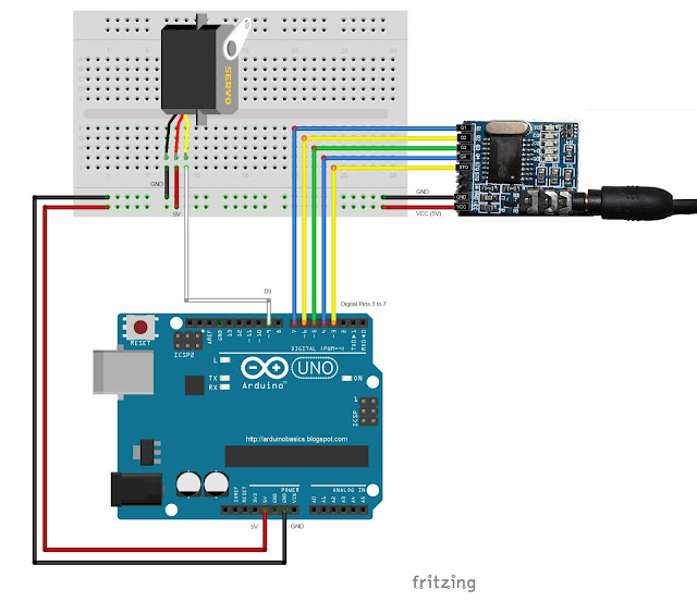
Connect the Arduino to the MT8870 DTMF module, and to a Servo.
Use the following Fritzing sketch as a guide.
 
(Click the image above to enlarge it)


Discussion


You will need to connect a cable from the DTMF module's 3.5mm port to that of your smart phone, computer, voice recorder or any other DTMF source of your choice.


When you power up your Arduino, the Servo motor should turn all the way to the left to it's zero position. Once the DTMF module receives a DTMF signal, it will identify the relevant frequecies as described in the table at the beginning of this tutorial, and produce a binary like output. You will notice the DTMF module's onboard LEDs light up when a tone is detected. Onboard LED (D5) will turn on for the length of the DTMF tone it just received, and turn off when the tone has stopped. On the other hand, the onboard LEDs (D1 to D4) will light up depending on the tone received, and will remain lit until the module receives another tone. The onboard LEDs are a visual representation of the voltages applied to the DTMF module's pins (Q1 to Q4, and STQ). Q1 matches D1, Q2 matches D2 etc etc. and STQ matches D5.
 
You will notice that there are two STQ pins on the DTMF module. The STQ pin that is closest to Q4 will only go high when a DTMF tone is detected, and will remain high for the duration of the tone. The other STQ pin is the exact opposite. It will switch LOW when a tone is received and remain LOW for the duration of the tone. When there is no tone, this STQ pin will remain HIGH. The table below provides a summary of the DTMF module outputs, with a blue box representing a voltage applied to that pin (HIGH), whereas a black box indicates no voltage applied (LOW).


In order to follow this project, you need a source of DTMF tones. You can produce DTMF tones using a touch-tone phone, or through the use of a DTMF Pad app. If you are feeling creative, you can create a DTMF song/tune like the one I posted on YouTube. You can see the video below:


As you can see from the video, I also recorded the DTMF tune onto a voice recorder, and was able to control the servo that way. If you are not feeling creative, you can visit this website to create DTMF tones from your browser.

Concluding comments


This project was very fun, and shows some novel ways to control your Arduino. After completing the project, I realised that I could use this module to alert me when new emails or messages arrive on my phone or computer. If you have the ability to change the email or message notification sound to a DTMF tone, you should be able to get the module and Arduino to respond accordingly. Oh well, maybe I'll save that project for another day.
 
If this project helped you in anyway or if you use my code within your project, please let me know in the comments below. I would be interested to see what you did.


If you like this page, please do me a favour and show your appreciation :

 
Visit my ArduinoBasics Google + page.
Follow me on Twitter by looking for ScottC @ArduinoBasics.
I can also be found on Pinterest and Instagram.
Have a look at my videos on my YouTube channel.


However, if you do not have a google profile...
Feel free to share this page with your friends in any way you see fit.

Hackaday Prize Entry: An Arduino Alarm System

The last few years have seen an incredible increase in the marketing for home automation devices. Why this tech is just picking up now is something we’ll never understand – home automation systems have been around for decades, mostly in the form of security systems. For his Hackaday Prize entry, [IngGaro] is building an Arduino-based security system that does everything you would expect from a home automation system, from closing the shutters to temperature monitoring.

[IngGaro]’s system is built around a shield for an Arduino Mega. This shield includes connections to an alarm system, a GSM modem, temperature and humidity sensors, an Ethernet module, and IR movement sensors. This Arduino Mega attaches to a control box mounted near the front door that’s loaded up with an LCD, an NFC and RFID reader, and a few buttons to arm and disarm the system.

This project has come a long way since it was featured in last year’s Hackaday Prize. Since then [IngGaro] finally completed the project thanks to a change in the Ethernet library. It’s much more stable now, and has the ability to completely control everything in a house that should be automated. Now all [IngGaro] needs to do is create a cool PCB for the project, but in our opinion you can’t do much better than the mastery of perfboard this project already has.

The 2015 Hackaday Prize is sponsored by:


Filed under: The Hackaday Prize

New Project: Make an Apple Watch Door Unlocker

Use an Apple Watch to automagically open doors at home or at work with a tap on your wrist.

Read more on MAKE

The post Make an Apple Watch Door Unlocker appeared first on Make: DIY Projects, How-Tos, Electronics, Crafts and Ideas for Makers.

Arduino Controlled Air Conditioner

Now that summer is coming, it’s time to break out the Air Conditioners! There are some old AC units out there that still work just fine, but nowadays we are used to everything being remotely controlled and automatic. [Phil] had an old window-mounted AC unit that still worked but was installed in a not-so-convenient place. To access the AC’s controls, one would have to climb over a large desk. This is a perfect opportunity to use the plethora of widely available hobby electronics to make an automatic AC controller retrofit.

First things first, there needs to be a way to turn the current control knob on the AC. [Phil] modeled up a 3D bracket to hold an RC car servo to the AC control panel. Attached to the servo horn is a slotted cylinder sized appropriately to fit the shape of the control knob. An Arduino measures the temperature of the room via a DS18B20 temperature sensor which then has the servo turn the control knob to the appropriate position, on or off. The Arduino sends temperature data back to a PC via MegunoLink Pro which graphs past data and also displays current temperature data. Using MegunoLink Pro, the min/max temperature points can also be set without uploading a new sketch to the Arduino.

From the temp vs time graph, it looks like the room temperature stays a consistent 23 +/- 1 °C. [Phil] did us summer-swelterers a favor and made all his design files available. This is a great idea but wonder if leaving the air conditioner unit switch in the ‘on’ position and turning the unit on/off via a relay connected to the 120vac line would work just as well.


Filed under: home hacks

Raspberry Pi and Arduino Home Automation

Electronichamsters design home automation platform using Raspberry Pi and Arduino

Read more on MAKE

Home Automation with a Custom Wireless Sensor Network

We’re no strangers to home automation projects around here, but it’s not often that you see one described in this much detail. [Paul] designed a custom home automation system with four teammates for an undergraduate thesis project.

The system is broken into two main components; the server and the peripherals. The team designed their peripherals from early prototypes of an upcoming ArduIMU v4 measurement unit. They removed all of the default sensors to keep costs down and reduce assembly time. The units can them be hooked up to various peripherals such as temperature sensors, mains relays, RGB color strips, etc.

The central management of the system is performed using a web-based user interface. The web server runs on Java, and interacts with the peripherals wirelessly. Basic messages can be sent back and forth to either read the state of the peripherals or to change the state. As far as the user is concerned, these messages appear as simple triggers and actions. This makes it very simple to program the peripherals using if, then, else logic.

The main project page is a very brief summary of what appears to be a very well documented project. The team has made available their 182 page final report (pdf), which goes into the nitty-gritty details of the project. Also, be sure to watch the demonstration video below.


Filed under: home hacks

THP Entry: Cut Energy Consumption by 30 percent with this WiFi XBee Setup

Let’s be honest. Paying electricity bills sucks. The amount paid is always too much, and the temperatures in the building are rarely set at a comfortable level. But now, with the help of this DIY Climate Control system, power-users can finally rejoice knowing that the heating and cooling process of their home (or commercial space) can be easily controlled through the utilization of an XBee Remote Kit and a process called zoning.

The team behind the project is [Doug], [Benjamin] and [Lucas]. They hope to solve the inconsistent temperature problems, which are caused by a moving sun, by open-sourcing their work into the community.

Their XBee system runs on a mesh network making it a perfect tool for sensing and communicating which areas in the house are too hot or too cold. Once the data is collected, XBee modules route the information wirelessly to each other until it reaches a central Arduino gatekeeper; which then decides if it wants to heat, ventilate, or air condition the room.

Not to mention all the added benefits posted below:

For one, you can hook-up temperature ICs like the TMP36 (PDF) without the need to buy extra parts. Better yet, the XBee can be programmed to fall asleep thus saving battery life. This means that the whole module can run on rechargeable AAA batteries.

Even further, it can be coded at its various ports to read other devices. This is great because it gives the setup the potential to turn on and off devices that are hooked to the module, transforming it into a networked hub of interconnected devices.

This approach not only allows you to be involved in saving the planet, but it keeps your home, warehouse, or office building at a much more comfortable level in the process, a real win-win.


The project featured in this post is an entry in The Hackaday Prize. Build something awesome and win a trip to space or hundreds of other prizes.


Filed under: home hacks, The Hackaday Prize

Long Range Wireless Sensors for the Home-Area-Network

In the near future, we will all reside in households that contain hundreds of little devices intertwingled together with an easily connectable and controllable network of sensors. For years, projects have been appearing all around the world, like this wireless sensor system that anyone can build.

[Eric] hopes his work will help bring the truly expansive Home-Area-Network (HAN) into fruition by letting developers build cheap, battery-powered, long-range wireless sensors. His method integrates with the pluggable OSGI architecture and home automation platform openHAB along with using an Arduino as the lower power, sensor node that is capable of utilizing many types of cheap sensors found online.

[Eric]’s tutorial depicts a few examples of the possibilities of these open-source platforms. For instance, he shows what he calls a ‘Mailbox Sentinel’ which is a battery-powered mail monitoring device that uses a Raspberry Pi to play the infamous, and ancient AOL sound bite “you’ve got mail.” It will also send an email once the postman cometh.

In addition, he lists other ideas such as a baby monitoring sentinel, a washer/dryer notification system, water leak detectors, and security implementations that blast a loud alarm if someone tries to break in. All of this potential for just around $20.

The key to making this project work, as [Eric] states, is the MQTT binding that ties together the Ardiuno and openHAB platform. This allows for simple messages to be sent over the Ethernet connection which is often found in IoT devices.

So all you developers out there go home and start thinking of what could be connected next! Because with this system, all you need is a couple of ten-spots and an internet plug, and you have yourself a strong foundation to build on top of. The rest is up to you.

This open, connected device is [Eric's] entry for The Hackaday Prize. You can see his video demo after the break. We hope this inspires you to submit your own project to the contest!


Filed under: home hacks, The Hackaday Prize

Arduino At Heart EZ Control for home automation goes wireless – 8 days left


We’re happy to share with you the update of the Indiegogo campaign of the Arduino At Heart for home automation we presented some time ago. Ez Control goes wireless!

———————————–

We have been silent for most of the time of this campaign, but this doesn’t means that we were sleeping. Not at all!

We were listening and interacting. We have received your comments, we have followed the topic on Reddit, we have exchanged ideas with many of you and we spent all this time improving our product.

Some of you was concerned about the relay, maybe too small. Some other concern was related to the position of the temperature sensor, that could offer false reading caused by the heat from other components.

We have upgraded the relay with a new one, rated 5A, and we have also improved the physical insulation for the high voltage circuit. We have then improved the insulation of the temperature sensor.

Sure all interesting, but those where not the main doubts about our hardware.

The most requested upgrade was related to the connectivity.

Why in 2014 do we use wires?

We admit that going wireless it was in our plans for the future. We wanted to start with an easy to use board, affordable and based on well known technologies, open to most of the users.

Reading and listening all your comments, we have understood that we should change our plan, and we did it.

Yes! We spent the past month with design, engineering, prototyping and testing of the brand new and immediately available EZboard WiFi!

This means that every perk and everyone will receive NOT the old board based on the cables and 10Mbit Ethernet controller, but this new, fantastic, WiFi development board.

And the price will not change!!!

Andrea & the EZBoard team

————–

Read all the info on Indiegogo and support them now!

A REST API for Arduino and the CC3000 WiFi Chip

Marco Schwarz is an electrical engineer and passionate about home automation. He wrote us some weeks ago to present his work on the Arduino Yún:

I was recently playing with the Arduino Yún for a whole set of new projects, and I discovered a sketch that implements a REST API for the Arduino Yún. We’ll see in more details what a REST API is, but for now let’s say it allows to standardise the communication between your Arduino and the external world via WiFi or Ethernet, and develop complex applications without having to modify your Arduino sketch every time.

So I told myself: why not create one REST API for the CC3000 WiFi chip ? That’s exactly what I did as a weekend project, and I wanted to share it with you. If you want to directly jump to the project files, go over to the GitHub repository of the project.

Keep reading on his blog or watch the video below: