Posts with «led matrix» label

A Tiny LED Matrix is Better With Friends

When we last heard from [lixielabs] he was building Nixie tube replacements out of etched acrylic and LEDs. Well he’s moved forward a few decades to bring us the Pixie, a chainable, addressable backpack for tiny LED matrix displays.

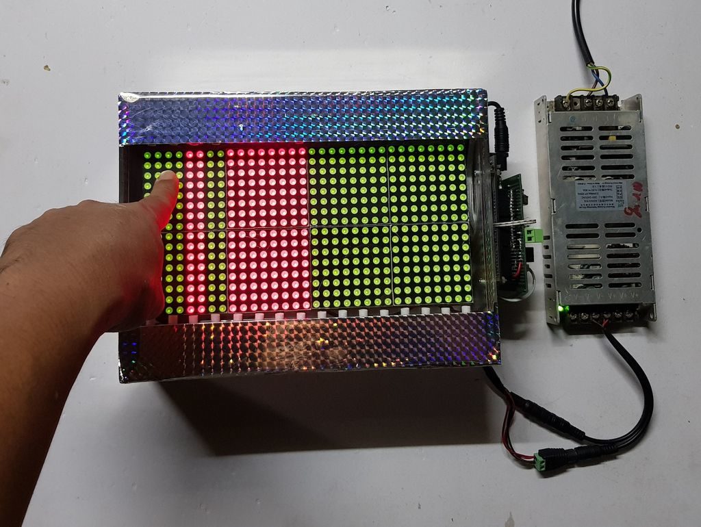
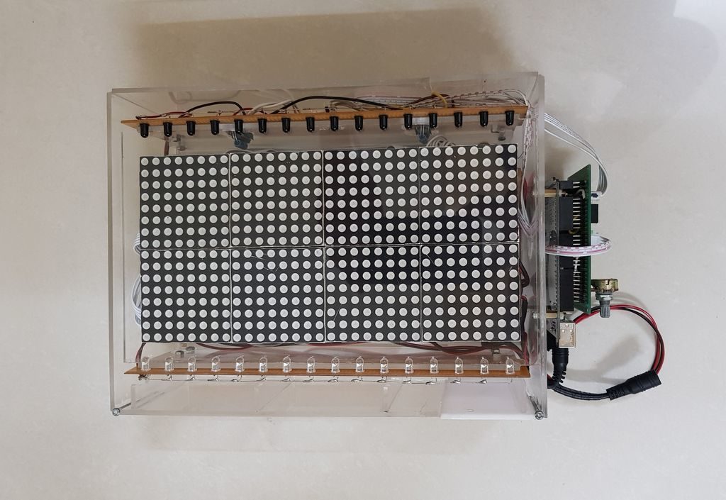
Each Pixie module is designed to host two gorgeous little Lite-On LTP-305G/HR 5×7 LED dot matrix displays, which we suspect have been impulse purchases in many a shopping cart. Along with the displays there is a small matrix controller and an ATTINY45 to expose a friendly electrical interface. Each module is designed to be mounted edge to edge and daisy chained out to 12 or more (with two displays each) for a flexible display any size you need. But to address the entire array only two control pins are required (data and clock).

[lixielabs] has done the legwork to make using those pins as easy as possible. He is careful to point out the importance of a good SDK and provides handy Arduino libraries for common microcontrollers and a reference implementation for the Raspberry Pi that should be easy to crib from to support new platforms. To go with that library support is superb documentation in the form of a datasheet (complete with dimensions and schematic!) and well stocked GitHub repo with examples and more.

To get a sense of their graphical capabilities, check out a video of 6 Pixie’s acting as a VU meter after the break. The Pixie looks like what you get when a hacker gets frustrated at reinventing LED dot matrix control for every project and decided to solve it once and for all. The design is clean, well documented, and extremely functional. We’re excited to see what comes next!

ESP32 with an I2S mic running FFT with 1024 cells, with each octave overlaid to make a 12-note chromagram, being rendered live by Pixies!https://t.co/0nWQfX0W6W pic.twitter.com/UZgh5ymWAw

— Lixie Labs (@lixielabs) September 22, 2020

Slot Machine Has a Handle on Fun

For some reason, when slot machines went digital, they lost their best feature — the handle. Who wants to push a button on a slot machine, anyway? Might as well just play video poker. [John Bradnam] seems to agree, and has built an open-source three-color matrix slot machine complete with handle.

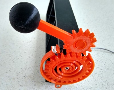
In this case, you’ll be losing all of your nickels to an Arduino Pro Mini. The handle is an upgrade to an earlier slot machine project that uses three 8×8 matrices and a custom driver board. When the spring-loaded handle is pulled, it strikes a micro switch to spins the reels and then snaps back into place. Between each pull, the current score is displayed across the matrix. There’s even a piezo buzzer for victory squawks. We only wish the button under the handle were of the clickier variety, just for the feels. Check out the short demo video after the break.

If you’re not a gambler, you could always turn your slot machine into a clock.

Cakeday Countdown Clock is a Sweet Little Scroller

If you want strangers to give you well wishes on your birthday out in the real world, you have call attention to the occasion by wearing a pointy hat or a button that says ‘today is my birthday, gimme presents’. But on your reddit cakeday, aka the day you joined, you’re automatically singled out with the addition of a slice of 8-bit cake next to your username. The great thing about your cakeday is that you’re almost guaranteed to get some karma for once, especially if you make something cakeday related like [ScottyD]’s cakeday countdown clock. But plenty of people forget what their cakeday is and miss out on the fun.

This countdown clock works like you might expect — every day that isn’t your cakeday, a message scrolls by with the number of days remaining until your next one. When the big day comes, the message becomes TODAY IS YOUR CAKE DAY. Both messages are bookended by cute little pixelated cake slices that we would apply liberally to the day-of message if we made one of these.

This simple but fun project shouldn’t put too big of a dent in your parts box, since it’s essentially an Arduino, a real-time clock module, and a 32×8 LED matrix to display the text. We love the uni-body design of the enclosure because it creates a shelf for the Arduino and gives easy access for gluing in the display from the rear. If for some reason you don’t reddit, then make one anyway and use it to count down to your IRL birthday or something. We’ve got the build video cut and plated for you to consume after the break.

We would understand if 2020 is supplying you with enough existential crises, but if not, consider building a clock that counts down the rest of your life expectancy.

Via r/duino

HDSP clock with SCD5583 display

Here is another interesting "intelligent" LED matrix display, whose name actually makes some sense (unlike HDSP-2354, among many others): SCD5583A. I reckon it means: "Serial Character Display with 5x5x8 dot matrix". 3 is the code for green (0 for red, 1 for yellow).
This display is now obsolete (replaced by touch screens in avionics, the industry for which it was designed), but it is still available on ebay for a reasonable price (except for incredibly high shipping cost).

Compared to other intelligent displays like the above-mentioned HDSP-2534 employed by the HDSP clock (hence the bland unimaginative name), SCD558X does not have an internally-defined font and requires the user to provide one. This makes it a little more complicated to use, but also allows for more flexibility, making it truly international (non-English character set). Even more, each pixel can be addressed individually, like a graphical 5x40 LED matrix.
The fact that is serial means fewer pins are required for interfacing (3 control pins in this case) and less driving circuitry (no need for the external shift register).

The photo below shows the display connected to an Arduino and running the HDSP sketch adapted for SCD5833.


Practically, the HDSP sketch uses only one function to write to display, aptly called "writeDisplay()", that needs to be re-written. The support for SCD5583 is provided by the class SCD5583, shown below (header + cpp files, compiled with Arduino IDE 1.8.13).

#ifndef _SCD5583_H_
#define _SCD5583_H_

#include  "Arduino.h"

class SCD5583
{
  public:
    SCD5583(byte loadPin, byte dataPin, byte clkPin);
    void clearMatrix();
    void setBrightness(byte b);
    void writeLine(char text[9]);

  private:
    void _sendData(byte data);
    void _getCharDefinition(byte* rows, char c);
    void _selectIndex(byte position);

    byte _loadPin;
    byte _dataPin;
    byte _clkPin;
};

#endif // _SCD5583_H_
-----------------------------------------------
#include "SCD5583.h"
#include "font5x5.h"

#define MAX_CHARS 8   // set to 10 for SCD5510X (10 digits) or to 4 for SCD554X (4 digits);
#define NUM_ROWS  5

SCD5583::SCD5583(byte loadPin, byte dataPin, byte clkPin)
{
  pinMode(loadPin, OUTPUT);
  pinMode(dataPin, OUTPUT);
  pinMode(clkPin, OUTPUT);
  _loadPin = loadPin;
  _dataPin = dataPin;
  _clkPin  = clkPin;
  clearMatrix();
//  setBrightness(0);
}

void SCD5583::clearMatrix()
{
  _sendData(B11000000);
}

void SCD5583::setBrightness(byte b)
{
  if (b > 0 && b < 7)
  {
     _sendData(B11110000 + b);
  }
}

void SCD5583::_selectIndex(byte position)
{
   _sendData(B10100000 + position);
}

void SCD5583::_sendData(byte data)
{
  byte mask = 1;
  digitalWrite(_loadPin, LOW);
  digitalWrite(_clkPin,  LOW);
  for (byte i = 0; i < 8; i++)
  {
    digitalWrite(_dataPin, mask & data? HIGH : LOW);
    digitalWrite(_clkPin, HIGH);
//  delay(10);
    digitalWrite(_clkPin, LOW);
    mask = mask*2;
  }
  digitalWrite(_loadPin, HIGH);
}

void SCD5583::_getCharDefinition(byte* rows, char c)
{
  for (byte i = 0; i < NUM_ROWS; i++)
  {
    rows[i] = font5x5[((c- 0x20) * NUM_ROWS) + i];
  }
}

void SCD5583::writeLine(char* text)
{
  byte rows[NUM_ROWS];
  for (int i = 0; i < MAX_CHARS; i++)
  {
    _selectIndex(i);
    _getCharDefinition(rows, text[i]);
    for (int r = 0; r < NUM_ROWS; r++)
    {
      _sendData(rows[r]);
    }
  }
}

As mentioned previously, the font must be provided too (content of file "font5x5.h" shown below):

#ifndef _FONT5X5_H_
#define _FONT5X5_H_

// ascii characters 0x41-0x7a (32-127);
static unsigned char font5x5[] =
{
  0x00, 0x20, 0x40, 0x60, 0x80, // space
  0x04, 0x24, 0x44, 0x60, 0x84, // !
  0x0A, 0x2A, 0x40, 0x60, 0x80, // "
  0x0A, 0x3F, 0x4A, 0x7F, 0x8A, // #
  0x0F, 0x34, 0x4E, 0x65, 0x9E, // $
  0x19, 0x3A, 0x44, 0x6B, 0x93, // %
  0x08, 0x34, 0x4D, 0x72, 0x8D, // &
  0x04, 0x24, 0x40, 0x60, 0x80, // '
  0x02, 0x24, 0x44, 0x64, 0x82, // (
  0x08, 0x24, 0x44, 0x64, 0x88, // )
  0x15, 0x2E, 0x5F, 0x6E, 0x95, // *
  0x04, 0x24, 0x5F, 0x64, 0x84, // +
  0x00, 0x20, 0x40, 0x64, 0x84, // ,
  0x00, 0x20, 0x4E, 0x60, 0x80, // -
  0x00, 0x20, 0x40, 0x60, 0x84, // .
  0x01, 0x22, 0x44, 0x68, 0x90, // /
  0x0E, 0x33, 0x55, 0x79, 0x8E, // 0
  0x04, 0x2C, 0x44, 0x64, 0x8E, // 1
  0x1E, 0x21, 0x46, 0x68, 0x9F, // 2
  0x1E, 0x21, 0x4E, 0x61, 0x9E, // 3
  0x06, 0x2A, 0x5F, 0x62, 0x82, // 4
  0x1F, 0x30, 0x5E, 0x61, 0x9E, // 5
  0x06, 0x28, 0x5E, 0x71, 0x8E, // 6
  0x1F, 0x22, 0x44, 0x68, 0x88, // 7
  0x0E, 0x31, 0x4E, 0x71, 0x8E, // 8
  0x0E, 0x31, 0x4F, 0x62, 0x8C, // 9
  0x00, 0x24, 0x40, 0x64, 0x80, // :
  0x00, 0x24, 0x40, 0x6C, 0x80, // ;
  0x02, 0x24, 0x48, 0x64, 0x82, // <
  0x00, 0x3F, 0x40, 0x7F, 0x80, // =
  0x08, 0x24, 0x42, 0x64, 0x88, // >
  0x0E, 0x31, 0x42, 0x64, 0x84, // ?
  0x0E, 0x35, 0x57, 0x70, 0x8E, // @
  0x04, 0x2A, 0x5F, 0x71, 0x91, // A
  0x1E, 0x29, 0x4E, 0x69, 0x9E, // B
  0x0F, 0x30, 0x50, 0x70, 0x8F, // C
  0x1E, 0x29, 0x49, 0x69, 0x9E, // D
  0x1F, 0x30, 0x5E, 0x70, 0x9F, // E
  0x1F, 0x30, 0x5E, 0x70, 0x90, // F
  0x0F, 0x30, 0x53, 0x71, 0x8F, // G
  0x11, 0x31, 0x5F, 0x71, 0x91, // H
  0x0E, 0x24, 0x44, 0x64, 0x8E, // I
  0x01, 0x21, 0x41, 0x71, 0x8E, // J
  0x13, 0x34, 0x58, 0x74, 0x93, // K
  0x10, 0x30, 0x50, 0x70, 0x9F, // L
  0x11, 0x3B, 0x55, 0x71, 0x91, // M
  0x11, 0x39, 0x55, 0x73, 0x91, // N
  0x0E, 0x31, 0x51, 0x71, 0x8E, // O
  0x1E, 0x31, 0x5E, 0x70, 0x90, // P
  0x0C, 0x32, 0x56, 0x72, 0x8D, // Q
  0x1E, 0x31, 0x5E, 0x74, 0x92, // R
  0x0F, 0x30, 0x4E, 0x61, 0x9E, // S
  0x1F, 0x24, 0x44, 0x64, 0x84, // T
  0x11, 0x31, 0x51, 0x71, 0x8E, // U
  0x11, 0x31, 0x51, 0x6A, 0x84, // V
  0x11, 0x31, 0x55, 0x7B, 0x91, // W
  0x11, 0x2A, 0x44, 0x6A, 0x91, // X
  0x11, 0x2A, 0x44, 0x64, 0x84, // Y
  0x1F, 0x22, 0x44, 0x68, 0x9F, // Z
  0x07, 0x24, 0x44, 0x64, 0x87, // [
  0x10, 0x28, 0x44, 0x62, 0x81, // \
  0x1C, 0x24, 0x44, 0x64, 0x9C, // ]
  0x04, 0x2A, 0x51, 0x60, 0x80, // ^
  0x00, 0x20, 0x40, 0x60, 0x9F, // _
  0x0A, 0x2A, 0x40, 0x60, 0x80, // '
  0x00, 0x2E, 0x52, 0x72, 0x8D, // a
  0x10, 0x30, 0x5E, 0x71, 0x9E, // b
  0x00, 0x2F, 0x50, 0x70, 0x8F, // c
  0x01, 0x21, 0x4F, 0x71, 0x8F, // d
  0x00, 0x2E, 0x5F, 0x70, 0x8E, // e
  0x04, 0x2A, 0x48, 0x7C, 0x88, // f
  0x00, 0x2F, 0x50, 0x73, 0x8F, // g
  0x10, 0x30, 0x56, 0x79, 0x91, // h
  0x04, 0x20, 0x4C, 0x64, 0x8E, // i
  0x00, 0x26, 0x42, 0x72, 0x8C, // j
  0x10, 0x30, 0x56, 0x78, 0x96, // k
  0x0C, 0x24, 0x44, 0x64, 0x8E, // l
  0x00, 0x2A, 0x55, 0x71, 0x91, // m
  0x00, 0x36, 0x59, 0x71, 0x91, // n
  0x00, 0x2E, 0x51, 0x71, 0x8E, // o
  0x00, 0x3E, 0x51, 0x7E, 0x90, // p
  0x00, 0x2F, 0x51, 0x6F, 0x81, // q
  0x00, 0x33, 0x54, 0x78, 0x90, // r
  0x00, 0x23, 0x44, 0x62, 0x8C, // s
  0x08, 0x3C, 0x48, 0x6A, 0x84, // t
  0x00, 0x32, 0x52, 0x72, 0x8D, // u
  0x00, 0x31, 0x51, 0x6A, 0x84, // v
  0x00, 0x31, 0x55, 0x7B, 0x91, // w
  0x00, 0x32, 0x4C, 0x6C, 0x92, // x
  0x00, 0x31, 0x4A, 0x64, 0x98, // y
  0x00, 0x3E, 0x44, 0x68, 0x9E, // z
  0x06, 0x24, 0x48, 0x64, 0x86, // {
  0x04, 0x24, 0x44, 0x64, 0x84, // |
  0x0C, 0x24, 0x42, 0x64, 0x8C, // }
  0x00, 0x27, 0x5C, 0x60, 0x80, // ~
};

#endif  // _FONT5X5_H_

And finally, the changes in HDSP.ino are:

1. add the following line at the top:
#include "SCD5583.h"

// SCD5583 pins: LOAD to D4, DATA to D5, SDCLK to D3;
SCD5583 scd(4,5,3);
2. replace the function writeDisplay() written for HDSP-2534, with the following:
void writeDisplay()
{
  scd.writeLine(displayBuffer);
}

Hardware-wise, some re-wiring is required on the HDSP board, starting with the removal of the 595 shift register. Then, D3, D4 and D5 (ATmega328 pins 5, 6, 11) must be connected respectively to SDCLK, LOAD and DATA pins (1, 2, 27) of the SCD5583 display.

And there you have it, a working HDSP clock with SCD5583 display.

It is worth mentioning that the measured current drawn was between 10mA (lowest brightness) and 20mA (highest), and that it works similarly well when powered by 3V3.


Arduino Drives a 600-Character Display

[Peterthinks] admits he’s no cabinet maker, so his projects use a lot of hot glue. He also admits he’s no video editor. However, his latest video uses some a MAX7219 to create a 600 character scrolling LED sign. You can see a video of the thing, below. Spoiler alert: not all characters are visible at once.

The heart of the project is a MAX7219 4-in-1 LED display that costs well under $10. The board has four LED arrays resulting in a display of 8×32 LEDs. The MAX7219 takes a 16-bit data word over a 10 MHz serial bus, so programming is pretty easy.

The MAX chip can decode for seven-segment displays or just allow you to light up the outputs directly, which is what the code here does. You can cascade the chips, so it is possible to string more than one of these modules together.

The code is available on Dropbox. The code is extremely simple due to the use of the Parola library and a MAX72XX library. We’ve seen a number of projects based around this chip. Some of the uses are pretty novel.

LED matrix made touch sensitive with infrared control

If you’d like to integrate touch functionality to your LED matrix project, then tuenhidiy may have just the thing for you

The setup uses 16 pairs of IR emitter and receivers arranged down the length of the bi-color 16×32 matrix to tell when one has inserted a finger or other object into an area. When sensed, it changes the corresponding column on the display from red to green or back again.

An Arduino Mega is used for overall control of the device, along with shift registers and multiplexers/demultiplexers to account for the massive amount of IO needed. 

Code for the build is available on GitHub, and you can see it demonstrated in the video below.

Use an LED matrix as a scanner

Consider that a digital camera uses an array of sensors to capture light from an object. Maker Marcio T, however, decided to turn this idea on its head and instead use an array of lights that are detected by a single sensor.

The way it works is that as each LED in a 32×32 matrix illuminates, a phototransistor picks up light if the path is clear or sees no change if the path is blocked. So when you put an object on the matrix, the sensor is able to get an accurate picture of it, enabling its Arduino Uno controller to then generate its silhouette. 

It’s a simple yet very clever hack, and if you pay close attention in the video below, you can see the lights scanning from the bottom to top before the image is produced.

Ordinary digital cameras work by using a large array of light sensors to capture light as it is reflected from an object. In this experiment, I wanted to see whether I could build a backwards camera: instead of having an array of light sensors, I have just a single sensor; but I control each of 1,024 individual light sources in a 32 x 32 LED matrix.

The way it works is that the Arduino illuminates one LED at a time, while using the analog input to monitor changes in the light sensor. This allows the Arduino to test whether the sensor can “see” a particular LED. This process is repeated for each of the 1,024 individual LEDs rapidly to generate a map of visible pixels.

If an object is placed between the LED matrix and the sensor, the Arduino is able to capture the silhouette of that object, which is lit up as a “shadow” once the capture is complete.

Arduino Blog 01 May 18:55

Making an LED matrix out of glue sticks

Glue sticks are great for attaching electronics and other bits to projects, but as Jon Bumstead shows in his latest work, they can also make pretty cool light diffusers. 

His project takes the form of a wooden box with plexiglass panels, allowing observers to see 64 vertical illuminated glue sticks inside. Hidden within the cube are 128 WS2811 LED modules, melted into the top and bottom of each stick. 

Everything is built around an Arduino Nano, using only a pair of its outputs to control each LED. User interface is provided by a button and knob to adjust speed, color, and patterns.

In this project, I created a “fiber optic” LED matrix using WS2801 LED strip and glue sticks. The light displays have a different look than similar LED cubes and a few advantages. First, you can’t see the actual LEDs in the display because the glue sticks guide the light away from the LEDs. Second, the device requires much fewer LEDs to make up the volume. Because the top and bottom have different LED strips, the fiber optic cables can take on two different colors that mix in the center. There are tons of different color displays that can be achieved with the device. I also added a button and knob for controlling the speed, color, and type of light display.

Petduino Is the DIY Tamagotchi You Can Hack

The Tamagotchi is a thing of the past. Bring your virtual pet into the 21st century with LEDs and an Arduino-compatible processor.

Read more on MAKE

The post Petduino Is the DIY Tamagotchi You Can Hack appeared first on Make: DIY Projects, How-Tos, Electronics, Crafts and Ideas for Makers.

New Project: LED Matrix Dessert Tray

Everyone loves dessert, but what if they could light up and play animations? I'll show you how to make a dessert tray with a built-in LED matrix.

Read more on MAKE

The post LED Matrix Dessert Tray appeared first on Make: DIY Projects, How-Tos, Electronics, Crafts and Ideas for Makers.